3
Specifications
Model Numbers Covered in this Specification
E50-D Electric Static Oven Range with 6 Radiant Elements.
E50-C Electric Static Oven Range with 4 Radiant Elements / 300mm Griddle.
E50-B Electric Static Oven Range with 2 Radiant Elements / 600mm Griddle.
E50-A Electric Static Oven Range with 900mm Griddle.
E56-D Electric Convection Oven Range with 6 Radiant Elements.
E56-C Electric Convection Oven Range with 4 Radiant Elements / 300mm Griddle.
E56-B Electric Convection Oven Range with 2 Radiant Elements / 600mm Griddle.
E56-A Electric Convection Oven Range with 900mm Griddle.
General
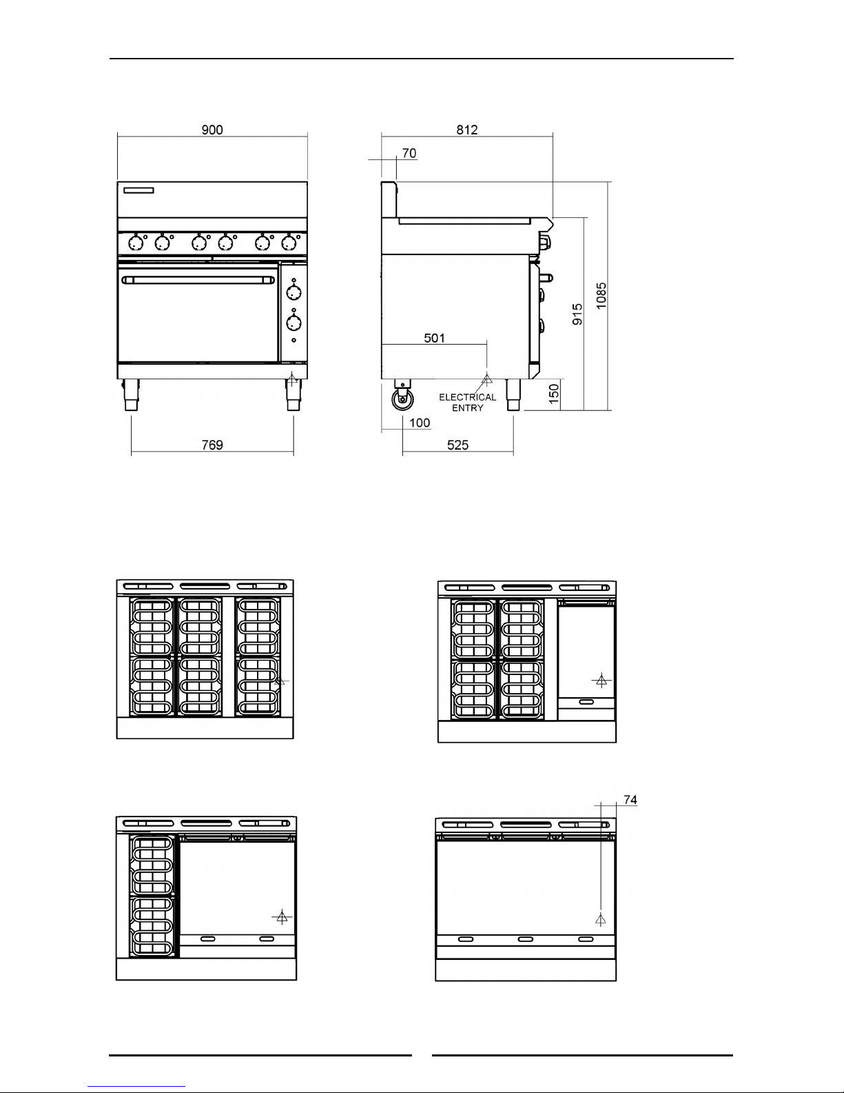
A commercial heavy duty, 900mm wide Electric Oven Range designed for modular kitchens and is
constructed in an easy clean stainless steel external finish.
The range is fitted with either a 900mm 6.5kW electric static oven or convection oven.
The hob is divided into modular sections of griddle plates and radiant elements (solid or open).
Electrical Supply Requirements
Electrical Connection
Electrical supply connection point is located at the rear of the appliance, approximately 74mm from
the right hand side, 501mm from the rear and 150mm from the floor.
When connecting a this electric appliance to the mains supply, ensure that the following is carried
out:-
• An isolating switch is fitted within 2m of the appliance, but not on the appliance and in
such a position that the user does not have to reach across the cooking surface.
• Supply cord shall be oil-resistant, sheathed flexible cable and not lighter than ordinary
polychloroprene or other equivalent synthetic elastomer sheathed cord (as per AS / NZS
3191 part 2.10.11. or IEC 60245-IEC-57) e.g. HO5 RN-F Type.
• The branch supply line shall be individually overload protected to the correct current rating
and the supply chord shall be protected against any mechanical or thermal damage.
• A grommet is fitted around the wiring entry hole into the appliance.
• All wiring connections must be tight.
Refer to the appropriate wiring standards for the size of cable that is to be supplied to an appliance
for the current drawn on that line.
WARNING:
THIS APPLIANCE MUST BE EARTHED.IFTHE SUPPLY CORD IS DAMAGED, IT MUST BE REPLACED BY ASUITABLY
QUALIFIED PERSON IN ORDER TO AVOID AHAZARD.
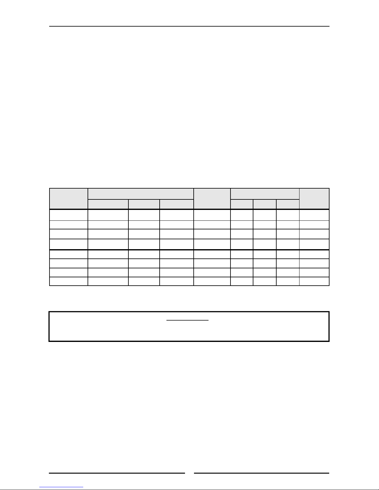
Model Total Power
Input
Amps @ 400 - 415 Vac Motor
Voltage Type Frequency L1 L2 L3
E50-D 400-415 Vac 3 P+N+E 50 / 60 Hz 20.9 kW 28.3 29.4 29.4 ----
E50-C 400-415 Vac 3 P+N+E 50 / 60 Hz 19.7 kW 22.5 29.4 29.4 ----
E50-B 400-415 Vac 3 P+N+E 50 / 60 Hz 18.5 kW 22.5 23.6 29.4 ----
E50-A 400-415 Vac 3 P+N+E 50 / 60 Hz 17.3 kW 22.5 23.6 23.6 ----
E56-D 400-415 Vac 3 P+N+E 50 Hz 21.2 kW 29.6 29.4 29.4 100 W
E56-C 400-415 Vac 3 P+N+E 50 Hz 20.0 kW 23.8 29.4 29.4 100 W
E56-B 400-415 Vac 3 P+N+E 50 Hz 18.8 kW 23.8 23.6 29.4 100 W
E56-A 400-415 Vac 3 P+N+E 50 Hz 17.6 kW 23.8 23.6 23.6 100 W
Power Supply