Blue Water Design A2X User manual
Blue Water Design
6260 Lookout Road Suite 210
Boulder, CO 80301
720.775.7109
http://bluewaterdesign.us
A2X User Manual
Version 1.0.3
2018-09-20

Table of Contents
About the A2X 3
ALERT2 Information 3
A2X Firmware Types 3
Power 3
Configuration and Control Software 4
Connecting to the A2X with A2Control 4
Device Configuration 4
Receiving Data 5
Transmitting Data 6
Status LEDs 6
Port Descriptions 7
Common Tasks 8
Initial Configuration 8
Upgrading Device Firmware 9
Local Upgrade 10
Remote Upgrade 10
Downloading ALERT2 Data and A2X System Logs 10
Remote Download: SFTP 11
Local Download: USB flash drive or microSD card 11
Clock Source Selection: GPS or NTP 12
Remote Configuration via IP Network 12
Pass and Reject Lists 12
Connectors, Cabling, and Pinouts 12
Serial ports 12
Radio ports 14
2

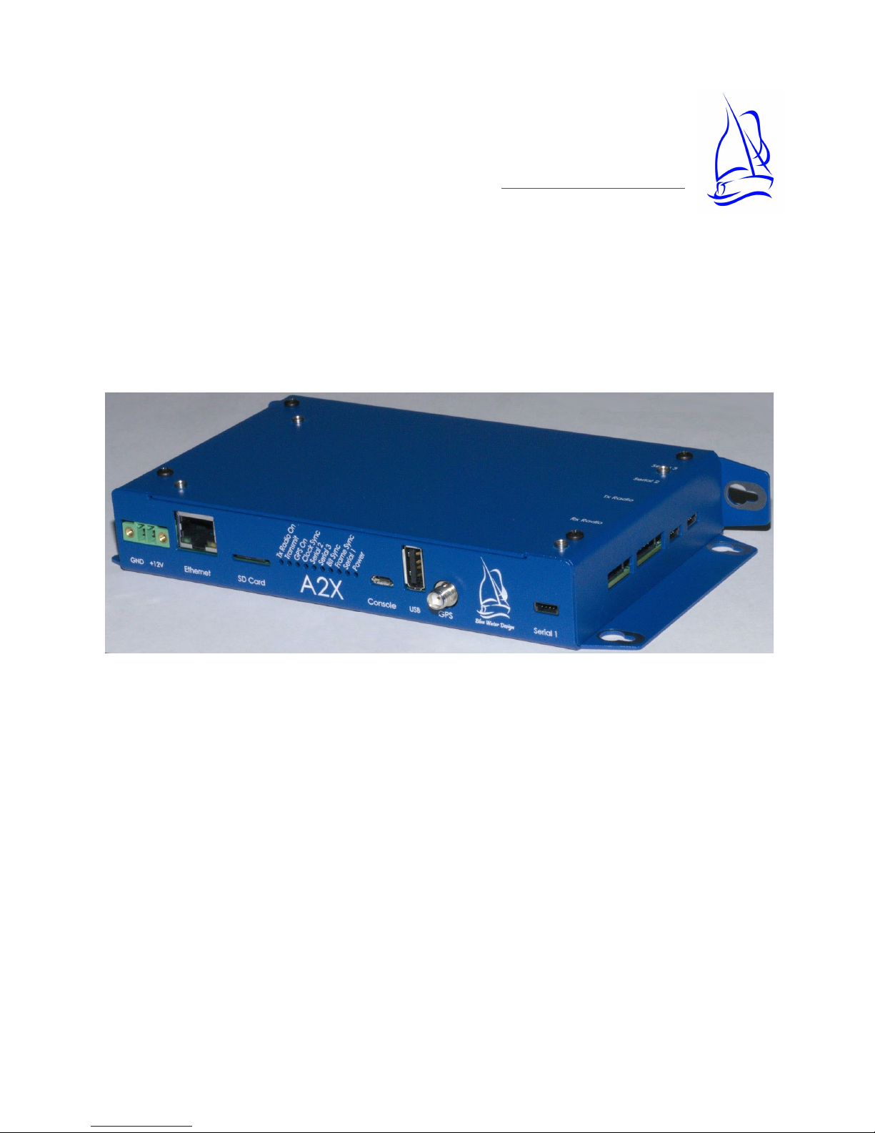
About the A2X
The A2X from Blue Water Design is a two-way capable ALERT2 Intelligent Network Device (IND),
which can act in any of the traditional ALERT2 roles: base station, repeater, or gauging site.
ALERT2 Information
ALERT2 is a low-bandwidth, high-reliability protocol designed for the transport of real-time data
over radio telemetry networks.
A Description of the ALERT2 Protocol , a white paper summarizing the protocol, opens with the
1
following description:
ALERT2 is a new protocol optimized for the transport of real-time data over radio
telemetry networks. It is the intended successor to the ALERT (Automated Local
Evaluation in Real Time) protocol introduced in the 1970s. It offers a 7- to 10-fold
increase in net data rate (or channel capacity), detects all errors introduced in
transmission and corrects the great majority of them. The new protocol comprises
multiple sub-protocols, with the flexibility to add new ones as needs emerge. It provides
greater “data space” that expands the range of sensor identifiers and data resolution. It
can be used in either ALOHA or TDMA environments, the latter providing the opportunity
to eliminate data contention altogether.
The protocol specification documents are linked from Blue Water Design’s support page, here.
A2X Firmware Types
The A2X is available with two different firmware types (IND or RPT), specified at the time of
purchase. The IND firmware is suitable for a gauging site or base station, but is not able to
repeat messages. The Repeater firmware adds repeater and address listing functionality.
The second set of letters in the A2X model number indicates the firmware (e.g., A2X-IND-BP).
Power
An external DC power source is required. The A2X can accept inputs ranging from 9 to 17 volts,
and includes reverse-polarity protection. Typical installations will provide power using 12V
lead-acid batteries. The A2X will monitor the input voltage level and include it in its regular
status reports.
1 A Descirption of the ALERT2 Protocol
, Don Van Wie, October, 2011,
http://bluewaterdesign.us/docs/ALERT2_Description_102511.pdf
3

Configuration and Control Software
Blue Water Design provides configuration and control software called A2Control as a
companion to the A2X. A2Control allows users to view received message, configure the A2X,
and transmit messages.
The software is available for download from the Blue Water Design website at:
http://bluewaterdesign.us/downloads/a2control
Connecting to the A2X with A2Control
●Connect your computer to the console port on the A2X using a MicroUSB cable.
● Launch A2Control.
●If there is only one attached serial port, A2Control will select it by default. Otherwise,
select the appropriate serial port from the dropdown in the top right of the window and
click the “Connect” button.
Image: The connect button and serial port selection drop-down
● If A2Control is able to communicate with the A2X, the firmware type and version of the
A2X will be shown in the toolbar along the top of the A2Control window as well as the
device’s IP address, if it is connected to the network.
● A2Control is also able to connect to the A2X remotely via TCP/IP by choosing network
connection in the serial port drop down instead of a port number. See “Remote
Configuration via IP Network” below.
Device Configuration
Device configuration is most easily performed using A2Control.
Connect to the device using A2Control as above, then select the gear icon in the toolbar to bring
up the configuration pane.
See the “Initial Configuration” section below for commonly used configuration settings.
When changes are complete, click the “Write To Device” button to save them. Settings may also
be loaded or saved to a local file.
4
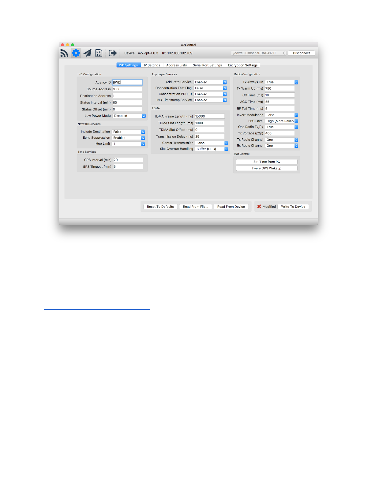
Image: The IND Settings page of A2Control
Device configuration can also be performed using the ALERT2 IND API to communicate with the
A2X over any of the available serial ports. The ALERT2 IND API specification is an open
standard published by the National Hydrologic Warning Council. More information is available
from the support page on the Blue Water Design website:
http://bluewaterdesign.us/support/
Receiving Data
The A2X will receive and decode ALERT2 data as long as it is powered on. When the A2X finds a
valid Bit Sync pattern in the incoming audio, it turns on the Bit Sync LED and begins listening for
a valid Frame Sync pattern (which should immediately follow the Bit Sync). If a valid Frame Sync
pattern is found, the Frame Sync LED is turned on as well, and both LEDs will remain illuminated
for the duration of the incoming message. If no valid frame sync is found, the Bit Sync LED is
turned off.
The A2X is a full-duplex modem, and will continue to decode ALERT2 messages while the
transmitter is active. (Note, however, that this requires a full-duplex radio configuration.)
To view incoming messages, connect to the device using A2Control, then select the “View
Messages” icon in the toolbar. Messages will appear as they are received.
5

Image: The Messages page of A2Control
Transmitting Data
The A2X is a fully-functional ALERT2 transmitter. Provided that it is configured with the GPS as
its clock source and that it has a good GPS signal, the A2X will use the assigned TDMA
(time-division multiple access) slot for transmission.
ALERT2 data can be submitted to the A2X for transmission using the ALERT2 IND API over any
of the serial ports, or transmissions can be initiated using A2Control on the “Transmit Data”
page. Additionally, the A2X will send status messages at user-configurable intervals and upon
acquisition and loss of the GPS clock sync.
Status LEDs
LEDs are visible on the front of the A2X case or may be brought to other locations via headers
on the board.
6

Name
Functional Description
TX Radio On
Power is being supplied to the TX radio.
Transmit
The A2X is transmitting an ALERT2 message.
GPS On
The GPS is currently powered up. The GPS may require several
minutes to initially get a fix, but after that will only require turning on
for a brief time to maintain accurate time.
Clock Sync
A solid light indicates that the A2X has a reliable clock source, and will
transmit in TDMA mode. The clock is able to maintain synchronization
for up to 4 hours without the GPS being on.
A slowly flashing light indicates that the the A2X is configured to use
NTP as its clock source and it has obtained an appropriate time from
an NTP server. The A2X will not transmit using TDMA with an NTP
time source.
Serial 1-3
This LED will flash as serial data is input or output from the
corresponding port.
Bit Sync
The Bit Sync light is illuminated when a valid ALERT2 Bit Sync pattern
has been found in the data stream from the RX radio. The light will
remain illuminated until a message is fully received or until it has been
determined that no message was present.
Frame Sync
The Frame Sync light is illuminated when a valid ALERT2 frame sync
has been found, and remains lit while the A2X attempts to decode the
message.
Power
The device has power and is running.
Port Descriptions
Name
Functional Description
Ethernet
Enables TCP/IP connections to the A2X. Possible uses include:
remote configuration of the A2X using the A2Control GUI, pulling logs
of collected ALERT2 data, streaming ALERT2 data to other endpoints,
and firmware updates.
SD Card
Stores logs of all received ALERT2 traffic and decoder operation.
7

Console
micro USB port. Intended for use with the A2Control GUI, but is
available an ALERT2 Binary API port. This port will appear a serial port
when plugged into a PC. Serial port settings are fixed at 115200 8,N,1.
When the device is booting, some diagnostic information may be
displayed.
USB
USB Host port, Supports plugging in a USB flash drive for copying logs
from the A2X, as well as firmware updates. If you want to copy the
ALERT2 logs from the device, create a folder called decoder_output on
the USB flash drive. If, and only if, the device finds this folder, ALERT2
output will be synchronized to the folder. The USB flash drive is also
used to install a firmware update.
GPS
A GPS antenna must be connected for proper time sync.
Serial 1
First serial port
RX Radio
4 pin connection for receive radio
TX Radio
5 pin connection for transmit radio
Serial 2
Second serial port
Serial 3
Third serial port
Common Tasks
Initial Configuration
The ALERT2 specification defines a wide range of configurable settings that can apply to an
IND. These configuration settings are divided into three categories: mandatory, recommended,
and optional. The A2X implements all mandatory and recommended settings, and many of the
optional configuration items as well.
Because there are some many configuration options, initial setup of an ALERT2 device can be
intimidating. In most cases, however, the default values are reasonable and need not be
changed. This section highlights values that users should consider changing.
All Units
Setting
Tab
Description
Agency ID
IND Settings
A unique string describing your agency. (e.g., UDFCD
8

or BWD)
Source Address
IND Settings
The unique address of this device. Addresses may
be managed through the Source Address
Management System (SAMS) at alert2.org
Network Password
IP Settings
A password that can be used to connect to this
device remotely
Serial Port Input /
Output Mode
Serial Port
Settings
Configure serial ports for API or Concentration input,
ASCII/Binary/No output
Receivers
Setting
Tab
Description
ASCII IP Forward
IP Settings
Comma separated list of hosts to which received
ALERT2 messages, in ASCII format, will be streamed
Binary IP Forward
IP Settings
Comma separated list of hosts to which received
ALERT2 messages, in Binary format, will be
streamed
Transmitters
Setting
Tab
Description
TDMA Frame Length
IND Settings
TDMA Configuration
TDMA Slot Length
IND Settings
TDMA Configuration
TDMA Slot Offset
IND Settings
TDMA Configuration
Transmission Delay
IND Settings
Delay into TDMA slot (set to 12 ms for 250ms slot)
Tx Voltage (p2p)
IND Settings
Set to 400 (Ritron) or 425 (Maxon) depending on the
transmit radio being used
Upgrading Device Firmware
Firmware images are available for download from the Blue Water Design here:
http://bluewaterdesign.us/downloads/firmware/
The update file must match the firmware of the device you wish to upgrade (e.g., an A2X-RPT-C
must use the a2x-rpt-update-... series of updates).
Please Note: The A2X firmware images end in a double extension (.tar.gpg); when downloading,
some browsers (Internet Explorer) may rename the files with only one extension (.tar). In this
case, you must rename the file to restore both extensions or the A2X will not find the update file.
9

Local Upgrade
To perform a firmware upgrade when you have physical access to the A2X, place the firmware
upgrade file in the root folder of a USB flash drive and insert that drive into the USB port on the
front of the A2X. The A2X must be powered on for at least two minutes for it to register the USB
flash drive.
Initially, you will see the “Bit Sync” LED flash rapidly while system logs are copied from the A2X
onto the flash drive (see Downloading ALERT2 Logs). When that is complete, the A2X will
search the drive for firmware updates. If one is found, the status LEDs -- starting with “Clock
Sync” -- will begin flashing slowing to display update progress. When the upgrade is complete,
the lights will remain solid for a few seconds and then the device will reboot.
If the Serial 1 light blinks quickly, the update has failed. You may attempt installing the update
again. If you continue having problems, please contact Blue Water Design for further
instructions.
Please Note: Some manufacturers ship USB flash drives with a default “exFAT” filesystem. The
A2X does not support exFAT, so you will need to reformat any such cards with the regular “FAT”
filesystem before using them with the A2X.
Remote Upgrade
The A2X can be upgraded remotely over a TCP/IP network using the SFTP protocol. Remote
access to the A2X is disabled by default, and must be enabled by setting a network password in
A2Control. Blue Water Design recommends the free and Open Source FileZilla as an SFTP client
(https://filezilla-project.org).
Connect to the A2X with the following parameters:
IP: [Configured / visible in A2Control]
Port: 4422
Username: alert2
Password: [specified in A2Control]
Once connected, simply upload the firmware update file to the default folder of the A2X to be
upgraded. When the upload completes, the A2X will automatically install the updated firmware
and reboot.
Downloading ALERT2 Data and A2X System Logs
The A2X ships with a microSD card which stores all received ALERT2 traffic. The microSD card
is intended to be left in the device during normal operation. It is not necessary to remove the
microSD card to obtain logs from the A2X; however, if you do remove the microSD card, power
down the A2X before doing so.
10

ALERT2 data can be retrieved from the A2X in three different ways: remotely, via SFTP; locally,
using a USB flash drive, or by removing the microSD card and copying data off of it directly.
Remote Download: SFTP
Remote access to the A2X is disabled by default, and must be enabled by setting a network
password in A2Control. Blue Water Design recommends the free and Open Source FileZilla
(https://filezilla-project.org) as an SFTP client.
Connect to the A2X with the following parameters:
IP: [Configured / visible in A2Control]
Port: 4422
Username: alert2
Password: [specified in A2Control]
Received ALERT2 data is stored in the decoder_output folder. Files are named
[AGENCY_ID]_[DATE].gz and are compressed with gzip.
System logs are stored in the logs folder. Each subsystem has its own folder with the most
recent logs stored in it. These logs are not intended to contain useful information for day-to-day
use of the system, but may be helpful for troubleshooting.
Local Download: USB flash drive or microSD card
When a USB flash drive is inserted, the A2X’s system logs are copied to the USB flash drive and
placed in a folder named [AGENCY_ID]-[SOURCE_ADDRESS]-[DATE]. To copy the received
ALERT2 data from the device, create a folder called decoder_output in the root folder of the USB
flash drive. If the A2X finds this folder, ALERT2 output files will be copied to the folder. The A2X
must be powered on for at least two minutes for it to register the USB flash drive.
Please Note: Some manufacturers ship USB flash drives with a default “exFAT” filesystem. The
A2X does not support exFAT, so you will need to reformat any such cards with the regular “FAT”
filesystem.
If, instead, you want to copy data directly from the microSD card, simply power off the A2X and
remove the card from the device. Reinsert the card after copying the data, before powering it on
again.
Please Note: The A2X will reformat the microSD if it does not understand the partition scheme
or filesystem, completely erasing the device. Some manufacturers ship microSD cards with a
default “exFAT” filesystem, which the A2X does not support. If you are worried about losing data
on a micro SD card, and are unsure of the filesystem type, DO NOT insert it into the A2X.
11

Clock Source Selection: GPS or NTP
In TDMA mode, an ALERT2 transmitter requires a 3D GPS fix in order to acquire accurate time.
For a receive-only site, it is optional, and the A2X will also support time synchronization using
the NTP protocol via the Ethernet port.
Remote Configuration via IP Network
It is possible to connect to a remote A2X over a TCP/IP network using A2Control.
Before you can connect to the remote device, you must first set a network password in the IP
Settings tab of the configuration pane in A2Control. The A2X ships with remote connections
disabled as a security precaution, so you must set this password locally the first time.
To connect to a remote A2X, select “Network Connection” in the dropdown to the left of the
“Connect” button, then enter the IP address or hostname of the device. When you click
“Connect”, you will be prompted to enter the network password.
Pass and Reject Lists
The A2X repeater firmware supports up to two different Pass or Reject lists for determining
which messages to repeat. Before a message is repeated, it is checked against all active
address lists.
Lists can be either a “Pass” list, where only listed entries are repeated, or a “Reject” list where
messages are repeated by default, but dropped if they are in the list. Messages can be filtered
by Source Address, Destination Address, or the path list added by other repeaters.
Messages can either be reported locally in the ALERT2 logs or dropped silently.
This lists can be configured on the Address Lists tab of the configuration pane in A2Control, or
they can be configured via the ALERT2 IND API.
Connectors, Cabling, and Pinouts
Serial ports
Three serial ports are available for use, and their function is configurable. The serial ports
operate at RS232 line levels.
12

Serial port Pinout (from left, facing the A2X):
Pin Number
Pin Function
1
TX (data output from A2X)
2
RX (data input to A2X)
3
Ground
The serial port connector is made by Harting Elektronik, part number 14310410301000.
The default serial port settings for all ports are:
Setting Name
Setting Value
Input Mode
API
Output Mode
ASCII
Baud Rate
9600
Parity
None
Stop Bits
1
Flow Control
None
Timeout
250ms
Independent Addressing
False/Off
Address
9000 (see above, not enabled by default)
Serial port settings can be configured using the ALERT2 IND API or via the “Serial Port Settings”
tab in the configuration pane of A2Control.
The A2X implements version 1.0 of the ALERT2 IND API. The specification document is linked
from the Blue Water Design website, here: http://bluewaterdesign.us/support/
Describing the details of the API is beyond the scope of this document, however at a very high
level:
- Sending messages with the A2X requires feeding it properly formatted API messages.
- If a serial port is configured for ASCII mode, messages may be inspected from any serial
terminal program (for example, Tera Term).
- If a serial port is configured for binary mode, software will be needed to properly decode
messages from the API binary format
13

- For a list of specific API commands implemented by the A2X, see the Blue Water Design
ALERT2 IND API Overview document, also available on our support page.
Radio ports
RX Pinout (from left, facing the A2X):
Pin Number
Pin Function
1
12V power (provided by A2X)
2
Ground
3
RF Data (input to A2X)
4
Channel Select
The RX radio connector is made by Harting Elektronik, part number 14310413101000.
TX Pinout (from left, facing the A2X):
Pin Number
Pin Function
1
RF Data (output from A2X)
2
Ground
3
Push to Talk
4
12V power (provided by A2X)
5
Channel Select
The TX radio connector is made by Harting Elektronik, part number 14310513101000.
Please Note: The RX Radio power path is designed to handle a maximum of 1.5 amps of
continuous current. The TX Radio power path is designed to handle up to 2.5 amps of
continuous current. Half-duplex repeater configurations, with a single radio, should favor using
the TX power path to power the radio.
14
Table of contents
Popular Network Hardware manuals by other brands

Panasonic
Panasonic Multi Chip Discrete UP05C8GF Specifications

H3C
H3C S7500 Series installation manual

PairGain
PairGain PF-FLEX FLC-704 manual

Elby Designs
Elby Designs Panther Series manual

Extron electronics
Extron electronics Low Profile Floor-Mount Raceway System for A/V Connectivity... installation guide

Omron
Omron WIRED REMOTE I-O - SYSTEM System manual


LTS
LTS LTN07128-R16 quick start guide

National Instruments
National Instruments DAQ AT-MIO-16X user manual

3Com
3Com 3C17203 - SuperStack 3 Switch 4400 Getting started guide

Cabletron Systems
Cabletron Systems Expansion module 9H532-17 user guide

SIBELL
SIBELL TD-3500 quick start guide

D-Link
D-Link DSN-6000 Series Quick installation guide