Blue-White CHEM-FEED C-1100E User manual
5300 Business Drive
Huntington Beach, CA 92649
USA
Phone: 714-893-8529 FAX: 714-894-9492
Website: www.blue-white.com
Blue-White
Industries, Ltd.
R
INJECTOR
®
MODEL C-1100 MODEL-E
POSITIVE DISPLACEMENT INJECTOR PUMP
OPERATING MANUAL

TABLE OF CONTENTS
1.....Introduction .....................................................................................3
2.....Specifications........................... ............................ ............................3
3.....Features............................................................................................3
4.....Unpacking........................................................................................3
5.....Installation ................. ............................ ............................ ..............4
5.1..Mounting location ............. ............................ ............................4
5.2..Input power connections ................. ............................ ..............5
5.3..External input signal connections................................ ..............6
5.4..How to install the tubing and fittings.........................................8
6.....How to operate the Pump .................................................................9
6.1..How to adjust the output - manual stroke adjustment................9
6.2..Electronic pump output controls ................................. ..............10
6.3..Mode 0 - FVS System set-up.....................................................10
6.4..Mode 1 - Manually Adjusting the output....... ............................13
6.5..Mode 2 - 4-20 mA input................................ ............................14
6.6..Mode 3 - 0-10 VDC input . ............................ ............................16
6.7..Mode 4 - Frequency (Hz) input ..................... ............................19
6.8..Mode 5 - Pulse input (Batch).....................................................20
6.9..Measuring the pump output - Volumetric test ............................21
7.....How to maintain the Pump....... ............................ ............................22
7.1..Routine inspection and cleaning.................................. ..............22
7.2..How to clean the pump ................... ............................ ..............22
7.3..500 hour service warning timer.................................................22
Pump head and Valve exploded view drawing .................................23
Replacement parts drawing ..............................................................24
Replacement parts list ......................................................................25
Warranty information. ............................ ............................ ..............26
Authorized service centers ....... ............................ ............................27
Page 2
2.0 Specifications
Maximum Working Pressure 150 psig / 10.4 bar (most models)
o o
Maximum Fluid Temperature 130 F / 54 C
o o
Ambient Temperature Range 14 to 110 F / -10 to 43 C
Duty Cycle Continuous
Maximum Viscosity 1,000 Centipoise
Maximum Suction Lift up to 20 ft. water
Power Requirements 115V/60Hz 14 & 30 RPM (1.37A max.)
115V/60Hz 45, 60, 125, 250 RPM (1.87A max.)
230V/60Hz 14 & 30 RPM (0.64A max.)
230V/60Hz 45, 60, 125, 250 RPM (0.74A max.)
220V/50Hz 14 & 30 RPM (0.68A max.)
220V/50Hz 45, 60, 125, 250 RPM (1.14A max.)
240V/50Hz 14 & 30 RPM (0.66A max.)
240V/50Hz 45, 60, 125, 250 RPM (1.04A max.)
Dimensions 6-1/4” H x 10-1/8” W x 9” D
Weight 8 lb. / 3.6 Kg
Page 3
1.0 Introduction
Congratulations on purchasing the C-1100 Model-E positive displacement
metering pump. The C-1100 is designed to inject chemicals into piping
systems and is capable of injecting against a high system pressure up to 150
PSI (10.4 bar). In addition to the front mounted mechanical flow rate
adjustment, the C-1100 Model-E unit is equipped with an external input
control circuitry which allows the pumps output to be externally controlled
by either a 4-20mA input signal, a 0-10V DC input signal or a pulsed input
signal.
C-1100E C-1100E
4.0 Unpacking
Your pump package should contain the following:
1 - Injector pump
1 - suction tube footvalve & strainer assembly
1 - ceramic tubing weight
1 - 5’ Length of clear PVC suction tubing
1 - 5’ Length of opaque LLDPE discharge tubing
1 - Injection fitting with internal back-flow check valve
1 - Mounting hardware kit
3.0 Features
!Double-ball, springless ceramic check valves with PVDF (Kynar) body,
TFE/P (Aflas) and Viton o-ring seals.
!Easy access, front mounted mechanical feed rate adjustment.
!High outlet pressure capability of 150 psig (most models).
!4000:1 adjustment turn down ratio.
!Digital electronic feed rate control.
!Corrosion proof Valox housing.
!Tamper resistant electronic control panel cover.

TABLE OF CONTENTS
1.....Introduction .....................................................................................3
2.....Specifications........................... ............................ ............................3
3.....Features............................................................................................3
4.....Unpacking........................................................................................3
5.....Installation ................. ............................ ............................ ..............4
5.1..Mounting location ............. ............................ ............................4
5.2..Input power connections ................. ............................ ..............5
5.3..External input signal connections................................ ..............6
5.4..How to install the tubing and fittings.........................................8
6.....How to operate the Pump .................................................................9
6.1..How to adjust the output - manual stroke adjustment................9
6.2..Electronic pump output controls ................................. ..............10
6.3..Mode 0 - FVS System set-up.....................................................10
6.4..Mode 1 - Manually Adjusting the output....... ............................13
6.5..Mode 2 - 4-20 mA input.... ............................ ............................14
6.6..Mode 3 - 0-10 VDC input . ............................ ............................16
6.7..Mode 4 - Frequency (Hz) input ..................... ............................19
6.8..Mode 5 - Pulse input (Batch).....................................................20
6.9..Measuring the pump output - Volumetric test ............................21
7.....How to maintain the Pump....... ............................ ............................22
7.1..Routine inspection and cleaning.................................. ..............22
7.2..How to clean the pump ................... ............................ ..............22
7.3..500 hour service warning timer.................................................22
Pump head and Valve exploded view drawing .................................23
Replacement parts drawing ..............................................................24
Replacement parts list ......................................................................25
Warranty information. ............................ ............................ ..............26
Authorized service centers ....... ............................ ............................27
Page 2
2.0 Specifications
Maximum Working Pressure 150 psig / 10.4 bar (most models)
o o
Maximum Fluid Temperature 130 F / 54 C
o o
Ambient Temperature Range 14 to 110 F / -10 to 43 C
Duty Cycle Continuous
Maximum Viscosity 1,000 Centipoise
Maximum Suction Lift up to 20 ft. water
Power Requirements 115V/60Hz 14 & 30 RPM (1.37A max.)
115V/60Hz 45, 60, 125, 250 RPM (1.87A max.)
230V/60Hz 14 & 30 RPM (0.64A max.)
230V/60Hz 45, 60, 125, 250 RPM (0.74A max.)
220V/50Hz 14 & 30 RPM (0.68A max.)
220V/50Hz 45, 60, 125, 250 RPM (1.14A max.)
240V/50Hz 14 & 30 RPM (0.66A max.)
240V/50Hz 45, 60, 125, 250 RPM (1.04A max.)
Dimensions 6-1/4” H x 10-1/8” W x 9” D
Weight 8 lb. / 3.6 Kg
Page 3
1.0 Introduction
Congratulations on purchasing the C-1100 Model-E positive displacement
metering pump. The C-1100 is designed to inject chemicals into piping
systems and is capable of injecting against a high system pressure up to 150
PSI (10.4 bar). In addition to the front mounted mechanical flow rate
adjustment, the C-1100 Model-E unit is equipped with an external input
control circuitry which allows the pumps output to be externally controlled
by either a 4-20mA input signal, a 0-10V DC input signal or a pulsed input
signal.
C-1100E C-1100E
4.0 Unpacking
Your pump package should contain the following:
1 - Injector pump
1 - suction tube footvalve & strainer assembly
1 - ceramic tubing weight
1 - 5’ Length of clear PVC suction tubing
1 - 5’ Length of opaque LLDPE discharge tubing
1 - Injection fitting with internal back-flow check valve
1 - Mounting hardware kit
3.0 Features
!Double-ball, springless ceramic check valves with PVDF (Kynar) body,
TFE/P (Aflas) and Viton o-ring seals.
!Easy access, front mounted mechanical feed rate adjustment.
!High outlet pressure capability of 150 psig (most models).
!4000:1 adjustment turn down ratio.
!Digital electronic feed rate control.
!Corrosion proof Valox housing.
!Tamper resistant electronic control panel cover.

CAUTION
ADJUST WHILE RUNNING
DISCHARGE LINES MAY BE
UNDER HIGH PRESSURE. USE
CARE TO PROTECT YOURSELF
WHEN DISCONNECTING.
MAX
MIN
12
3
4
5
6
7
8
9
LOOSEN THE LOCK SCREW
TURN KNOB TO DESIRED SETTING
RE-TIGHTEN THE LOCK SCREW
RUN
STANDBY
RUN
FIELD DIGIT MODE
PROGRAM
STAND-BY
PRIME
MINIMUM
MAXIMUM
INPUT MODES
1 - MANUAL 2 - 4-20mA 3 - 0-10VDC 4 - PULSE (Hz)
PROGRAM
RESET SERVICE
PRIME
DISPLAY
VARIABLE SPEED PUMP
% SPEED
1
MODE
VDC
SERVICE
1000
ALARM
mA Hz
5.0 Installation
Note: All diagrams are strictly for guideline purposes only. Always consult
an expert before installing the pump into specialized systems. The pump
should be serviced by qualified persons only.
5.1 Mounting Location
Choose an area located near the chemical supply tank, chemical injection
point and electrical supply. Although the pump is designed to withstand
outdoor conditions, a cool, dry, well ventilated location is recommended.
Install the pump where it can be easily serviced.
!Mount the pump to a secure surface or wall using the enclosed hardware.
Wall mount to a solid surface only. Mounting to drywall with anchors is not
recommended.
!Mount the pump close to the injection point. Keep the inlet (suction) and
outlet (discharge) tubing as short as possible. Longer discharge tubing
increases the back pressure at the pump tube.
!Your solution tank should be sturdy. Keep the tank covered to reduce
fumes. Do not mount the pump directly over your tank. Chemical fumes
may damage the unit. Mount the pump off to the side or at a lower level
than the chemical container.
!Mounting the pump lower than the chemical container will gravity feed the
chemical into the pump. This “flooded suction” installation will aid in
priming the pump and will reduce output error due to increased suction lift.
We recommended installing a shut-off valve, pinch clamp or other means to
halt the gravity feed to the pump during servicing.
!Be sure your installation does not constitute a cross connection with the
drinking water supply. Check your local plumbing codes.
Page 4 Page 5
CAUTION: Proper eye and skin protection must be
worn when installing and servicing the pump.
Floor Mount Wall Mount
7-3/8”
7-5/8”
3-1/2”
8-3/16”
Drill .156 Dia. (5/32)
For Self-Tap Screw
#10 X 1” Phillips Steel
4 Places
Drill .156 Dia. (5/32)
For Self-Tap Screw
#10 X 1” Phillips Steel
2 Places
INJECTOR MOUNTING
Note: For wall-mounting, drill & thread into
solid wood only.
TYPICAL INSTALLATION
Suction
Tube
Chemical
Container
with cover
Discharge
Tube
Strainer
Ceramic Weight
Injection / Check valve
with 1/4” and 1/2” male
pipe threads.
Mount in upward position
to prevent trapped gasses
in the injection fitting. Wall or shelf mount
away from the top of the
solution tank. Chemical
fumes can damage the
unit.
5.2 Input Power Connections
!Be certain to connect the pump to the proper supply voltage. Using the incorrect voltage will
damage the pump and may result in injury. The voltage requirement is printed on the pump
serial label.
!Removable resistors on the circuit board are factory preset for the correct voltage. See page 7
Circuit Board Connections diagram for details.
!The pump is supplied with a ground wire conductor and a grounding type attachment plug
(power cord). To reduce the risk of electric shock, be certain that the power cord is connected
only to a properly grounded, grounding type receptacle.
!POWER: 115V/60Hz 14 & 30 RPM (1.37A max.), 115V/60Hz 45, 60, 125, 250 RPM (1.87A
max.), 230V/60Hz 14 & 30 RPM (0.64A max.), 230V/60Hz 45, 60, 125, 250 RPM (0.74A
max.), 220V/50Hz 14 & 30 RPM (0.68A max.), 220V/50Hz 45, 60, 125, 250 RPM (1.14A
max.), 240V/50Hz 14 & 30 RPM (0.66A max.), 240V/50Hz 45, 60, 125, 250 RPM (1.04A
max.)
Note: When in doubt regarding your electrical installation, contact a licensed electrician.
WARNING: Risk of electric shock.
PARTS LOCATOR DRAWING
®
J-Box
Control Cover
Motor Housing
Rear Cover
Pumphead
6
Slide Clamps*
CAUTION
ADJUST WHILE RUNNING
DISCHARGE LINES MAY BE
UNDER HIGH PRESSURE. USE
CARE TO PROTECT YOURSELF
WHEN DISCONNECTING.
MAX
MIN
12
3
4
5
6
7
8
9
LOOSEN THE LOCK SCREW
TURN KNOB TO DESIRED SETTING
RE-TIGHTEN THE LOCK SCREW
Adjustment knob
10 IN. (254 MM)
1
4
IN.
10 IN. (267 MM)
(159 MM)
1
2
RUN
STANDBY
RUN
FIELD DIGIT MODE
PROGRAM
STAND-BY
PRIME
MINIMUM
MAXIMUM
INPUT MODES
1 - MANUAL 2 - 4-20mA 3 - 0-10VDC 4 - PULSE (Hz)
PROGRAM
RESET SERVICE
PRIME
DISPLAY
VARIABLE SPEED PUMP
% SPEED
1
MODE
VDC
SERVICE
1000
ALARM
mA Hz
Control Panel
C-1100E C-1100E

CAUTION
ADJUST WHILE RUNNING
DISCHARGE LINES MAY BE
UNDER HIGH PRESSURE. USE
CARE TO PROTECT YOURSELF
WHEN DISCONNECTING.
MAX
MIN
12
3
4
5
6
7
8
9
LOOSEN THE LOCK SCREW
TURN KNOB TO DESIRED SETTING
RE-TIGHTEN THE LOCK SCREW
RUN
STANDBY
RUN
FIELD DIGIT MODE
PROGRAM
STAND-BY
PRIME
MINIMUM
MAXIMUM
INPUT MODES
1 - MANUAL 2 - 4-20mA 3 - 0-10VDC 4 - PULSE (Hz)
PROGRAM
RESET SERVICE
PRIME
DISPLAY
VARIABLE SPEED PUMP
% SPEED
1
MODE
VDC
SERVICE
1000
ALARM
mA Hz
5.0 Installation
Note: All diagrams are strictly for guideline purposes only. Always consult
an expert before installing the pump into specialized systems. The pump
should be serviced by qualified persons only.
5.1 Mounting Location
Choose an area located near the chemical supply tank, chemical injection
point and electrical supply. Although the pump is designed to withstand
outdoor conditions, a cool, dry, well ventilated location is recommended.
Install the pump where it can be easily serviced.
!Mount the pump to a secure surface or wall using the enclosed hardware.
Wall mount to a solid surface only. Mounting to drywall with anchors is not
recommended.
!Mount the pump close to the injection point. Keep the inlet (suction) and
outlet (discharge) tubing as short as possible. Longer discharge tubing
increases the back pressure at the pump tube.
!Your solution tank should be sturdy. Keep the tank covered to reduce
fumes. Do not mount the pump directly over your tank. Chemical fumes
may damage the unit. Mount the pump off to the side or at a lower level
than the chemical container.
!Mounting the pump lower than the chemical container will gravity feed the
chemical into the pump. This “flooded suction” installation will aid in
priming the pump and will reduce output error due to increased suction lift.
We recommended installing a shut-off valve, pinch clamp or other means to
halt the gravity feed to the pump during servicing.
!Be sure your installation does not constitute a cross connection with the
drinking water supply. Check your local plumbing codes.
Page 4 Page 5
CAUTION: Proper eye and skin protection must be
worn when installing and servicing the pump.
Floor Mount Wall Mount
7-3/8”
7-5/8”
3-1/2”
8-3/16”
Drill .156 Dia. (5/32)
For Self-Tap Screw
#10 X 1” Phillips Steel
4 Places
Drill .156 Dia. (5/32)
For Self-Tap Screw
#10 X 1” Phillips Steel
2 Places
INJECTOR MOUNTING
Note: For wall-mounting, drill & thread into
solid wood only.
TYPICAL INSTALLATION
Suction
Tube
Chemical
Container
with cover
Discharge
Tube
Strainer
Ceramic Weight
Injection / Check valve
with 1/4” and 1/2” male
pipe threads.
Mount in upward position
to prevent trapped gasses
in the injection fitting. Wall or shelf mount
away from the top of the
solution tank. Chemical
fumes can damage the
unit.
5.2 Input Power Connections
!Be certain to connect the pump to the proper supply voltage. Using the incorrect voltage will
damage the pump and may result in injury. The voltage requirement is printed on the pump
serial label.
!Removable resistors on the circuit board are factory preset for the correct voltage. See page 7
Circuit Board Connections diagram for details.
!The pump is supplied with a ground wire conductor and a grounding type attachment plug
(power cord). To reduce the risk of electric shock, be certain that the power cord is connected
only to a properly grounded, grounding type receptacle.
!POWER: 115V/60Hz 14 & 30 RPM (1.37A max.), 115V/60Hz 45, 60, 125, 250 RPM (1.87A
max.), 230V/60Hz 14 & 30 RPM (0.64A max.), 230V/60Hz 45, 60, 125, 250 RPM (0.74A
max.), 220V/50Hz 14 & 30 RPM (0.68A max.), 220V/50Hz 45, 60, 125, 250 RPM (1.14A
max.), 240V/50Hz 14 & 30 RPM (0.66A max.), 240V/50Hz 45, 60, 125, 250 RPM (1.04A
max.)
Note: When in doubt regarding your electrical installation, contact a licensed electrician.
WARNING: Risk of electric shock.
PARTS LOCATOR DRAWING
®
J-Box
Control Cover
Motor Housing
Rear Cover
Pumphead
6
Slide Clamps*
CAUTION
ADJUST WHILE RUNNING
DISCHARGE LINES MAY BE
UNDER HIGH PRESSURE. USE
CARE TO PROTECT YOURSELF
WHEN DISCONNECTING.
MAX
MIN
12
3
4
5
6
7
8
9
LOOSEN THE LOCK SCREW
TURN KNOB TO DESIRED SETTING
RE-TIGHTEN THE LOCK SCREW
Adjustment knob
10 IN. (254 MM)
1
4
IN.
10 IN. (267 MM)
(159 MM)
1
2
RUN
STANDBY
RUN
FIELD DIGIT MODE
PROGRAM
STAND-BY
PRIME
MINIMUM
MAXIMUM
INPUT MODES
1 - MANUAL 2 - 4-20mA 3 - 0-10VDC 4 - PULSE (Hz)
PROGRAM
RESET SERVICE
PRIME
DISPLAY
VARIABLE SPEED PUMP
% SPEED
1
MODE
VDC
SERVICE
1000
ALARM
mA Hz
Control Panel
C-1100E C-1100E
ACCEPTABLE CABLE JACKET RANGE:
.118 - .255 INCH .( 3,0 - 6,5 MM)
EXTERNAL INPUT CABLE
5.3 External Input Signal Connections
The pump will accept a variety of external control input signals; 4-20 mA ,
0-10 VDC, TTL, CMOS, AC Sine Waves, Contact Closures, Hall Effect,
NPN. The 4-20mA and 0-10 VDC loops must be powered.
All wiring connections are to be made inside of the junction box located on
the side of the pump. Special connectors are not required. A liquid-tite
connector is supplied and should be used for the external signal cable. The
signal input wires are color coded to the type of signal being used.
Page 6 Page 7
INPUT
VOLTAGE
115V 60Hz
220V 50Hz
HOT
LEADWIRE
NEUTRAL
LEADWIRE
GROUND
LEADWIRE
230V 60Hz
YELLOW
YELLOW
YELLOW
BLUE
BROWN
RED
GREEN
GREEN
GREEN
MOTOR LEADWIRES
SIGNAL INPUT WIRE COLOR CODES
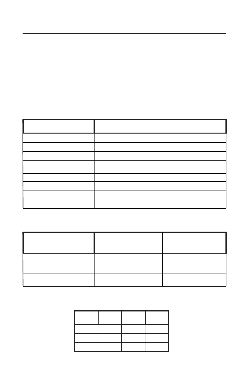
CIRCUIT BOARD CONNECTIONS
AC
MOTOR
Neutral (blue/brown/red)
Hot (yellow)
Ground (green)
Ground (green)
Common
Hot
AC
Input
Power
Power Circuit Board
(Top view)
Protector Fuse
2 Amps, 250 Volt AC
(little Fuse #235002
or Equivalent)
R R
2A
250VAC
T3
T2
T1
T4
LINE
HOT
LINE
NEUTRAL
MOTOR
NEUTRAL
MOTOR
SWITCHED
115V 50/60Hz
INPUT VOLTAGE
RESISTOR PLACEMENT
220V 50/60Hz
230V 50/60Hz
R R
R
MA = BLUE
GND = BLACK
RELAY = PURPLE (2)
VDC = ORANGE
VS = RED (+17V DC)
PLS = WHITE
JUNCTION BOX
LIQUID-TIGHT
CONNECTOR
MTR = BROWN
Alarm Relay
3A/125VAC
N/C
COM
N/O
Purple connection wires
Default is N/O
VS
VDC
MA
MTR
GND
PLS
CN3
VS
FVS
GND
TFD
GND
FVS+
CN4
Control Circuit Board
(Back view)
Program Disable Jumper - Located on front of Control board.
Un-installed = enable front panel programming (default)
Installed = disable front panel programming
External input connections
6 Wire bundle to junction box
Flow verification sensor connector
3 Wire bundle to junction box.
red/black/yellow
Tube failure detection sensor connector
2 Wire bundle to pump head sensor
(A-100N series pumps only)
WIRE COLOR CODE
INPUT TYPE
MOTOR ON SIGNAL
5-20V DC open collector output
closed while motor is energized
FLOW VERIFICATION SENSOR
4-20 mA
0-10 VDC
ALARM RELAY
BROWN (+) & BLACK (-)
PURPLE & PURPLE
WHITE (+) & BLACK (-)
BLUE (+) & BLACK (-)
TTL, CMOS
ORANGE (+) & BLACK (-)
RED/WHITE (+ 20VDC) & BLACK (-) & YELLOW (signal)
CONTACT (10v @ 2 mA max)
HALL EFFECT, NPN RED (+) & WHITE (-)
C-1100E C-1100E
PADDLEWHEEL SENSOR SIGNAL INPUT WIRING
PADDLEWHEEL SENSOR
WIRE COLOR CODE
BLUE-WHITE
PADDLEWHEEL
SENSOR TYPE
MODEL FH
HALL EFFECT SENSOR
BLACK (-)
RED (+)
PUMP INPUT
WIRE COLOR CODE
MODEL FC
AC SINE WAVE SENSOR
BARE (signal)
BLACK (-)
RED (+ 20VDC)
WHITE (signal)
BLACK (-)
RED (+)
BLACK (-)
WHITE (+)
ACCEPTABLE CABLE JACKET RANGE:
.118 - .255 INCH .( 3,0 - 6,5 MM)
EXTERNAL INPUT CABLE
5.3 External Input Signal Connections
The pump will accept a variety of external control input signals; 4-20 mA ,
0-10 VDC, TTL, CMOS, AC Sine Waves, Contact Closures, Hall Effect,
NPN. The 4-20mA and 0-10 VDC loops must be powered.
All wiring connections are to be made inside of the junction box located on
the side of the pump. Special connectors are not required. A liquid-tite
connector is supplied and should be used for the external signal cable. The
signal input wires are color coded to the type of signal being used.
Page 6 Page 7
INPUT
VOLTAGE
115V 60Hz
220V 50Hz
HOT
LEADWIRE
NEUTRAL
LEADWIRE
GROUND
LEADWIRE
230V 60Hz
YELLOW
YELLOW
YELLOW
BLUE
BROWN
RED
GREEN
GREEN
GREEN
MOTOR LEADWIRES
SIGNAL INPUT WIRE COLOR CODES
CIRCUIT BOARD CONNECTIONS
AC
MOTOR
Neutral (blue/brown/red)
Hot (yellow)
Ground (green)
Ground (green)
Common
Hot
AC
Input
Power
Power Circuit Board
(Top view)
Protector Fuse
2 Amps, 250 Volt AC
(little Fuse #235002
or Equivalent)
R R
2A
250VAC
T3
T2
T1
T4
LINE
HOT
LINE
NEUTRAL
MOTOR
NEUTRAL
MOTOR
SWITCHED
115V 50/60Hz
INPUT VOLTAGE
RESISTOR PLACEMENT
220V 50/60Hz
230V 50/60Hz
R R
R
MA = BLUE
GND = BLACK
RELAY = PURPLE (2)
VDC = ORANGE
VS = RED (+17V DC)
PLS = WHITE
JUNCTION BOX
LIQUID-TIGHT
CONNECTOR
MTR = BROWN
Alarm Relay
3A/125VAC
N/C
COM
N/O
Purple connection wires
Default is N/O
VS
VDC
MA
MTR
GND
PLS
CN3
VS
FVS
GND
TFD
GND
FVS+
CN4
Control Circuit Board
(Back view)
Program Disable Jumper - Located on front of Control board.
Un-installed = enable front panel programming (default)
Installed = disable front panel programming
External input connections
6 Wire bundle to junction box
Flow verification sensor connector
3 Wire bundle to junction box.
red/black/yellow
Tube failure detection sensor connector
2 Wire bundle to pump head sensor
(A-100N series pumps only)
WIRE COLOR CODE
INPUT TYPE
MOTOR ON SIGNAL
5-20V DC open collector output
closed while motor is energized
FLOW VERIFICATION SENSOR
4-20 mA
0-10 VDC
ALARM RELAY
BROWN (+) & BLACK (-)
PURPLE & PURPLE
WHITE (+) & BLACK (-)
BLUE (+) & BLACK (-)
TTL, CMOS
ORANGE (+) & BLACK (-)
RED/WHITE (+ 20VDC) & BLACK (-) & YELLOW (signal)
CONTACT (10v @ 2 mA max)
HALL EFFECT, NPN RED (+) & WHITE (-)
C-1100E C-1100E
PADDLEWHEEL SENSOR SIGNAL INPUT WIRING
PADDLEWHEEL SENSOR
WIRE COLOR CODE
BLUE-WHITE
PADDLEWHEEL
SENSOR TYPE
MODEL FH
HALL EFFECT SENSOR
BLACK (-)
RED (+)
PUMP INPUT
WIRE COLOR CODE
MODEL FC
AC SINE WAVE SENSOR
BARE (signal)
BLACK (-)
RED (+ 20VDC)
WHITE (signal)
BLACK (-)
RED (+)
BLACK (-)
WHITE (+)
Page 8 Page 9
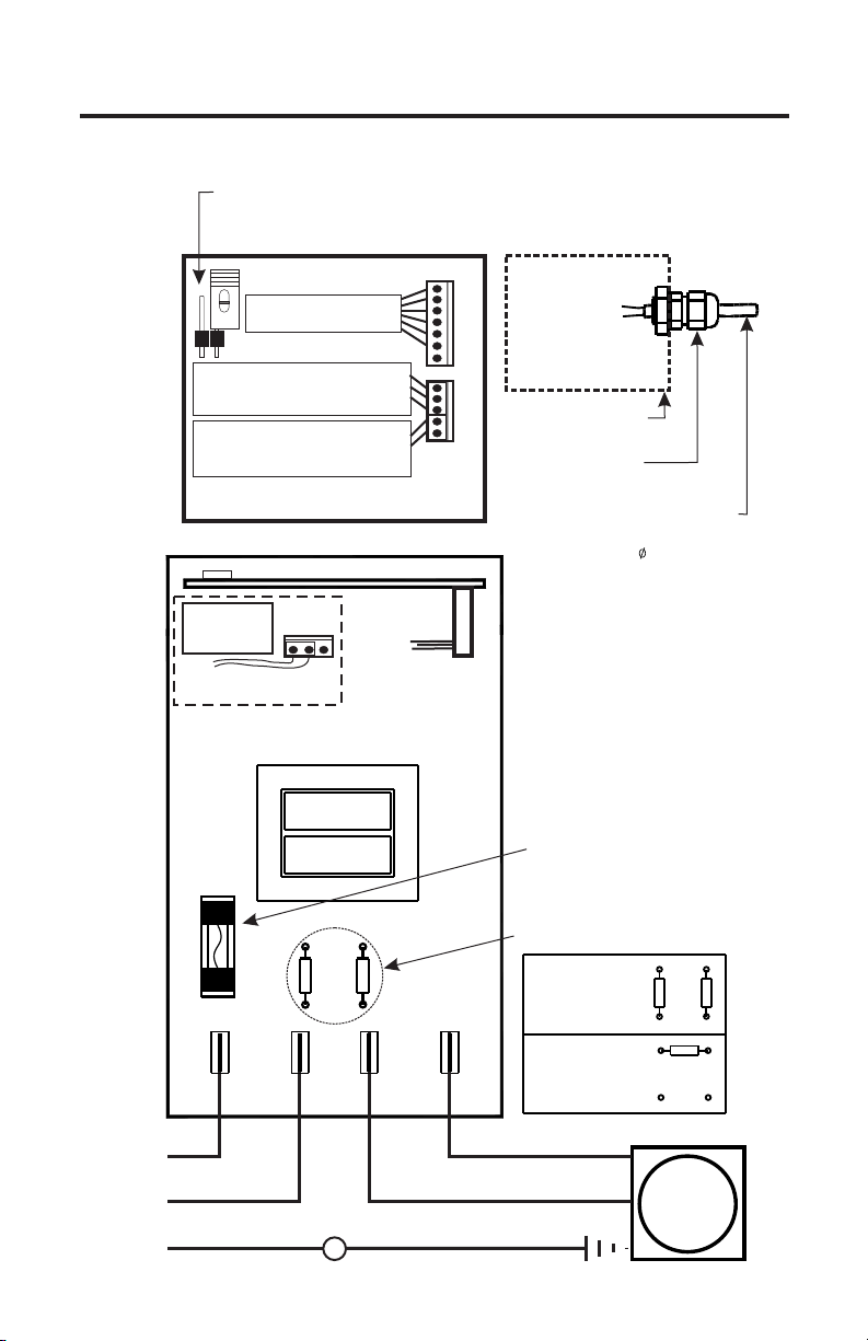
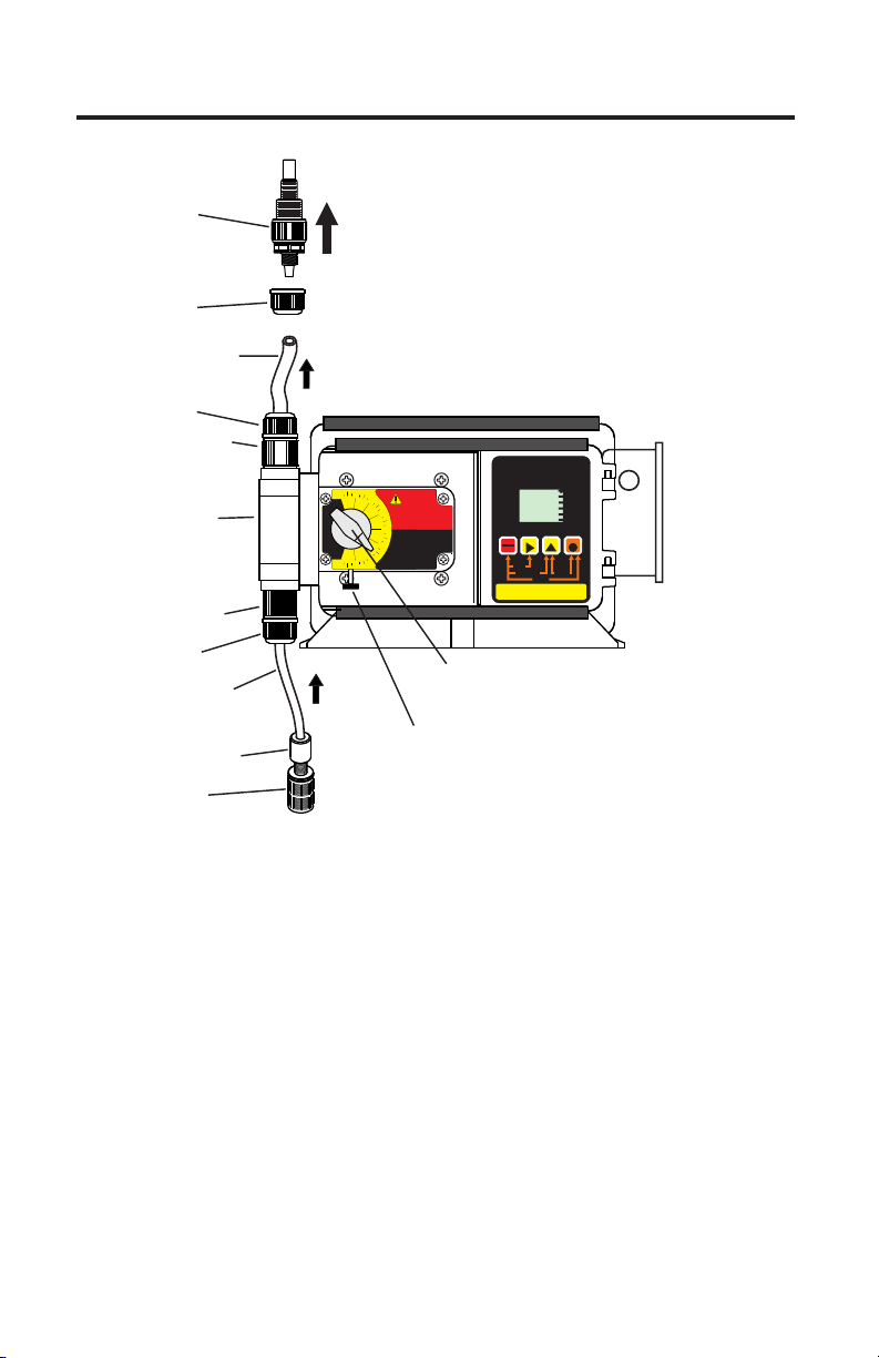
5.4 How To Install the Tubing and Fittings
!Inlet Tubing - Locate the inlet fitting of the pump head. Remove the tube
nut. Push the clear suction tubing through the tube nut and onto the fitting
barb. Hand tighten the tube nut to secure the tubing.
CAUTION: Proper eye and skin protection must be
worn when installing and servicing the pump.
!Footvalve/Strainer - Trim the inlet end
of the suction tubing so that the strainer
will rest approximately two inches from
the bottom of the solution tank. This will
prevent sediment from clogging the
strainer. Slip the ceramic weight over
the end of the suction tube. Press the
strainer’s barbed fitting into the end of
the tube. Secure the ceramic weight to
the strainer. Drop the strainer into the
solution tank.
!Injection/Check Valve Fitting
Installation - The Injection/Check valve
fitting is designed to install directly into
either 1/4” or 1/2” female pipe threads.
This fitting will require periodic
cleaning, especially when injecting
fluids that calcify such as sodium
hypochlorite. See section 7.0.
Install the Injection/Check valve directly
into the piping system. To prevent
trapped gasses, install the fitting in an
upward direction. Use PTFE thread
sealing tape on the pipe threads.
Push the opaque outlet (discharge)
tubing through the tube nut and onto the
compression barb of the Injection/Check
valve fitting. Hand tighten the tube nut
to secure the tubing.
FootValve
Strainer
Assembly
Ceramic
Weight
Suction Tubing
FOOTVALVE/STRAINER
!Outlet Tubing - Locate the outlet
fitting of the pump head. Remove the
tube nut. Push the opaque discharge
tubing through the tube nut and onto the
compression barb of the fitting. Hand
tighten the tube nut to secure the tubing.
Keep outlet tube as short as possible.
Discharge
Tubing
Tube retaining
nut
Injection
Check valve
Discharge Tube
(Rigid P.E.)
Outlet Adapter
Tube Nut
Inlet Adapter
Tube Nut
Suction Tubing
(clear PVC)
Manual
Stroke length
Adjustment knob
Footvalve
CAUTION
ADJUST WHILE RUNNING
DISCHARGE LINES MAY BE
UNDER HIGH PRESSURE. USE
CARE TO PROTECT YOURSELF
WHEN DISCONNECTING.
MAX
MIN
12
3
4
5
6
7
8
9
LOOSEN THE LOCK SCREW
TURN KNOB TO DESIRED SETTING
RE-TIGHTEN THE LOCK SCREW
Tube Nut
Injection
Check valve
RUN
STANDBY
RUN
FIELD DIGIT MODE
PROGRAM
STAND-BY
PRIME
MINIMUM
MAXIMUM
INPUT MOD ES
1 - MANUAL 2 - 4-20mA 3 - 0-10VDC
4 - 0-1000 Hz
PROGRAM
RESET SERVI CE
PRIME
DISPLAY
DIGITAL TIMER PUMP
1VDC
SERVICE
1000
ALARM
mA Hz
MODE
TFD
FVS
ON-T
TOT-TSECMINHR DAY
5 - PULSE (BATCH)
INJECTION/CHECK VALVE
6.0 How To Operate The Pump
6.1 How to adjust the output- manual stroke adjustment The
Pump flow rate can be adjusted within a range of 5% -100% of maximum
output (20:1 turndown ration) by means of a mechanical, cam type
mechanism. The mechanism adjusts the pump’s stroke length to an infinite
number of settings within the flow range.
ø Note: The pump’s output will reduce due to increased system pressure,
increased suction lift, and increased fluid viscosity. The pump must be over-
sized to allow for these factors. Sizing the pump to allow adjustment within
the midrange is preferred to maintain accuracy. Consult the factory for
individual pump model output curve data.
To adjust the pump’s output:
1. With the pump running, loosen the lock screw.
2. Turn the adjustment knob to the desired setting.
3. Re-tighten the lock screw.
Ceramic Weight
Lock Screw
Pump Head
C-1100E C-1100E
Pipe tee
Install
upward
Install
upward
Page 8 Page 9
5.4 How To Install the Tubing and Fittings
!Inlet Tubing - Locate the inlet fitting of the pump head. Remove the tube
nut. Push the clear suction tubing through the tube nut and onto the fitting
barb. Hand tighten the tube nut to secure the tubing.
CAUTION: Proper eye and skin protection must be
worn when installing and servicing the pump.
!Footvalve/Strainer - Trim the inlet end
of the suction tubing so that the strainer
will rest approximately two inches from
the bottom of the solution tank. This will
prevent sediment from clogging the
strainer. Slip the ceramic weight over
the end of the suction tube. Press the
strainer’s barbed fitting into the end of
the tube. Secure the ceramic weight to
the strainer. Drop the strainer into the
solution tank.
!Injection/Check Valve Fitting
Installation - The Injection/Check valve
fitting is designed to install directly into
either 1/4” or 1/2” female pipe threads.
This fitting will require periodic
cleaning, especially when injecting
fluids that calcify such as sodium
hypochlorite. See section 7.0.
Install the Injection/Check valve directly
into the piping system. To prevent
trapped gasses, install the fitting in an
upward direction. Use PTFE thread
sealing tape on the pipe threads.
Push the opaque outlet (discharge)
tubing through the tube nut and onto the
compression barb of the Injection/Check
valve fitting. Hand tighten the tube nut
to secure the tubing.
FootValve
Strainer
Assembly
Ceramic
Weight
Suction Tubing
FOOTVALVE/STRAINER
!Outlet Tubing - Locate the outlet
fitting of the pump head. Remove the
tube nut. Push the opaque discharge
tubing through the tube nut and onto the
compression barb of the fitting. Hand
tighten the tube nut to secure the tubing.
Keep outlet tube as short as possible.
Discharge
Tubing
Tube retaining
nut
Injection
Check valve
Discharge Tube
(Rigid P.E.)
Outlet Adapter
Tube Nut
Inlet Adapter
Tube Nut
Suction Tubing
(clear PVC)
Manual
Stroke length
Adjustment knob
Footvalve
CAUTION
ADJUST WHILE RUNNING
DISCHARGE LINES MAY BE
UNDER HIGH PRESSURE. USE
CARE TO PROTECT YOURSELF
WHEN DISCONNECTING.
MAX
MIN
12
3
4
5
6
7
8
9
LOOSEN THE LOCK SCREW
TURN KNOB TO DESIRED SETTING
RE-TIGHTEN THE LOCK SCREW
Tube Nut
Injection
Check valve
RUN
STANDBY
RUN
FIELD DIGIT MODE
PROGRAM
STAND-BY
PRIME
MINIMUM
MAXIMUM
INPUT MOD ES
1 - MANUAL 2 - 4-20mA 3 - 0-10VDC
4 - 0-1000 Hz
PROGRAM
RESET SERVI CE
PRIME
DISPLAY
DIGITAL TIMER PUMP
1VDC
SERVICE
1000
ALARM
mA Hz
MODE
TFD
FVS
ON-T
TOT-TSECMINHR DAY
5 - PULSE (BATCH)
INJECTION/CHECK VALVE
6.0 How To Operate The Pump
6.1 How to adjust the output- manual stroke adjustment The
Pump flow rate can be adjusted within a range of 5% -100% of maximum
output (20:1 turndown ration) by means of a mechanical, cam type
mechanism. The mechanism adjusts the pump’s stroke length to an infinite
number of settings within the flow range.
ø Note: The pump’s output will reduce due to increased system pressure,
increased suction lift, and increased fluid viscosity. The pump must be over-
sized to allow for these factors. Sizing the pump to allow adjustment within
the midrange is preferred to maintain accuracy. Consult the factory for
individual pump model output curve data.
To adjust the pump’s output:
1. With the pump running, loosen the lock screw.
2. Turn the adjustment knob to the desired setting.
3. Re-tighten the lock screw.
Ceramic Weight
Lock Screw
Pump Head
C-1100E C-1100E
Pipe tee
Install
upward
Install
upward

Page 10 Page 11
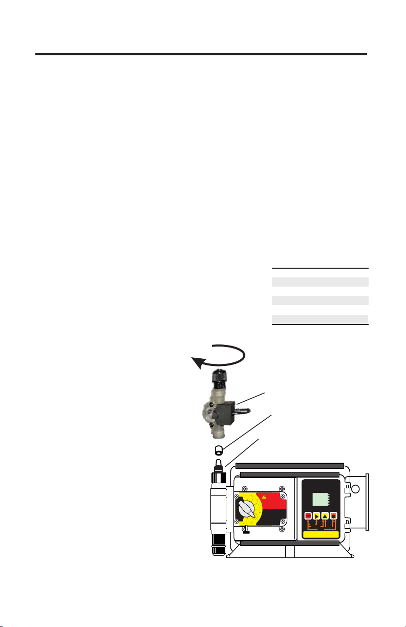
Install the FVS Flow Sensor -
The Flow Verification Sensor
(FVS) should be installed on the
discharge (outlet) pump head
valve. The sensor includes a
PVC tubing insert, located
inside the sensor’s female
thread connection, that is
designed to seal the sensor onto
the pump tube inlet adapter.
Thread the sensor onto the
pump tube until the tubing
insert is snug against the pump
tube inlet fitting - do not over-
tighten.
Connect the red/white, black,
and white wires from the sensor
to the red, black, and yellow
wires located in the pump’s
junction box. See page 7.
6.3 MODE 0 - FVS system set-up (sensor sold separately)
! (FVS) Flow Verification System The C-1100E is equipped with a -
Flow Verification System which is designed to stop the pump and provide a
contact closure output in the event the sensor does not detect chemical
during pump operation. This could indicate a clogged injection fitting,
empty chemical solution tank, loose tubing connection, etc.
To allow the pump to clear any gasses that may have accumulated during
stopped operation, an alarm delay time value from 1-256 seconds must be
programmed (An alarm delay value of 000 seconds disables the FVS
system). The pump will stop, and the alarm mode activated, if no pulses are
received by the pump and the alarm delay time period has ended. Press the
STAND-BY button twice to clear the alarm and restart the pump. The Flow
Verification Sensor is sold as an optional accessory.
6.2 Electronic Pump Output
Controls -
Open the control panel door by sliding the
upper and lower slide clamps to the left.
! RUN/STANDBY Button -
+Press to start and stop the pump. The
ARROW next to the word RUN will light
when in the run mode. The ARROW next
to the word STAND-BY will blink when in
the stand-by mode.
+Press to clear ALARM.
+When pressed with the FIELD Button, initiates a 99 second prime cycle
which temporarily overrides the mode setting and runs the pump motor at
100% speed. The ARROW next to the word PRIME will blink.
+When pressed with the DIGIT button, resets the 500 hour service warning
timer to zero.
+When pressed with the MODE button, initiates the programming mode.
The ARROW next to the word PROGRAM will blink.
!FIELD Button -
+In the programming mode, selects the digit to be changed.
!DIGIT Button -
+In the programming mode, increases the selected digit.
+When pressed with the MODE Button, toggles the display from operating
time cycle values to input signal value.
!MODE Button -
+Used to select one of five operating modes.
Mode 0 - FVS system set-up
Mode 1 - Manual Adjustment (external input disabled)
Mode 2 - 4-20mA input
Mode 3 - 0-10VDC input
Mode 4 - Frequency input adjusts cycle on-time
Mode 5 - Pulse input count = single batch time
RUN
STANDBY
RUN
FIELD DIGIT MODE
PROGRAM
STAND-BY
PRIME
MINIMUM
MAXIMUM
INPUT MODES
1 - MANUAL 2 - 4-20mA 3 - 0-10VDC
4 - 0-1000 Hz
PROGRAM
RESET SERVICE
PRIME
DISPLAY
DIGITAL TIMER PUMP
1VDC
SERVICE
1000
ALARM
mA Hz
MODE
TFD
FVS
ON-T
TOT-TSECMINHRDAY
5 - PULSE (BATCH)
Confirm the FVS flow range - The Flow
Verification Sensor (FVS) will only function
within its operating range. Sensor model FV-100-
6V has an operating range of 30-300 ml/min (1-10
oz/min). If the pump’s output is less than 30
ml/min (0.5 ml/sec), the sensor will not detect
chemical and a signal will not be sent to the pump.
OPERATING
FLOW RANGE
(ml/min)
30-300
FV-100-6V
100-1000
FV-200-6V
200-2000
FV-300-6V
300-3000
FV-400-6V
500-5000
FV-500-6V
700-7000
FV-600-6V
SENSOR
MODEL
NUMBER
Insert Tubing Seal
CAUTION
ADJUST WHILE RUNNING
DISCHARGE LINES MAY BE
UNDER HIGH PRESSURE. USE
CARE TO PROTECT YOURSELF
WHEN DISCONNECTING.
MAX
MIN
12
3
4
5
6
7
8
9
LOOSEN THE LOCK SCREW
TURN KNOB TO DESIRED SETTING
RE-TIGHTEN THE LOCK SCREW
RUN
STANDBY
RUN
FIELD DIGIT MODE
PROGRAM
STAND-BY
PRIME
MINIMUM
MAXIMUM
INPUT MODE S
1 - MANUAL 2 - 4-20mA 3 - 0-10VDC
4 - 0-1000 Hz
PROGRAM
RESET SERVIC E
PRIME
DISPLAY
DIGITAL TIMER PUMP
1VDC
SERVICE
1000
ALARM
mA Hz
MODE
TFD
FVS
ON-T
TOT-TSECMINHR DAY
5 - PULSE (BATCH)
Outlet Adapter
FVS Sensor
C-1100E C-1100E
Page 10 Page 11
Install the FVS Flow Sensor -
The Flow Verification Sensor
(FVS) should be installed on the
discharge (outlet) pump head
valve. The sensor includes a
PVC tubing insert, located
inside the sensor’s female
thread connection, that is
designed to seal the sensor onto
the pump tube inlet adapter.
Thread the sensor onto the
pump tube until the tubing
insert is snug against the pump
tube inlet fitting - do not over-
tighten.
Connect the red/white, black,
and white wires from the sensor
to the red, black, and yellow
wires located in the pump’s
junction box. See page 7.
6.3 MODE 0 - FVS system set-up (sensor sold separately)
! (FVS) Flow Verification System The C-1100E is equipped with a -
Flow Verification System which is designed to stop the pump and provide a
contact closure output in the event the sensor does not detect chemical
during pump operation. This could indicate a clogged injection fitting,
empty chemical solution tank, loose tubing connection, etc.
To allow the pump to clear any gasses that may have accumulated during
stopped operation, an alarm delay time value from 1-256 seconds must be
programmed (An alarm delay value of 000 seconds disables the FVS
system). The pump will stop, and the alarm mode activated, if no pulses are
received by the pump and the alarm delay time period has ended. Press the
STAND-BY button twice to clear the alarm and restart the pump. The Flow
Verification Sensor is sold as an optional accessory.
6.2 Electronic Pump Output
Controls -
Open the control panel door by sliding the
upper and lower slide clamps to the left.
! RUN/STANDBY Button -
+Press to start and stop the pump. The
ARROW next to the word RUN will light
when in the run mode. The ARROW next
to the word STAND-BY will blink when in
the stand-by mode.
+Press to clear ALARM.
+When pressed with the FIELD Button, initiates a 99 second prime cycle
which temporarily overrides the mode setting and runs the pump motor at
100% speed. The ARROW next to the word PRIME will blink.
+When pressed with the DIGIT button, resets the 500 hour service warning
timer to zero.
+When pressed with the MODE button, initiates the programming mode.
The ARROW next to the word PROGRAM will blink.
!FIELD Button -
+In the programming mode, selects the digit to be changed.
!DIGIT Button -
+In the programming mode, increases the selected digit.
+When pressed with the MODE Button, toggles the display from operating
time cycle values to input signal value.
!MODE Button -
+Used to select one of five operating modes.
Mode 0 - FVS system set-up
Mode 1 - Manual Adjustment (external input disabled)
Mode 2 - 4-20mA input
Mode 3 - 0-10VDC input
Mode 4 - Frequency input adjusts cycle on-time
Mode 5 - Pulse input count = single batch time
RUN
STANDBY
RUN
FIELD DIGIT MODE
PROGRAM
STAND-BY
PRIME
MINIMUM
MAXIMUM
INPUT MODES
1 - MANUAL 2 - 4-20mA 3 - 0-10VDC
4 - 0-1000 Hz
PROGRAM
RESET SERVICE
PRIME
DISPLAY
DIGITAL TIMER PUMP
1VDC
SERVICE
1000
ALARM
mA Hz
MODE
TFD
FVS
ON-T
TOT-TSECMINHRDAY
5 - PULSE (BATCH)
Confirm the FVS flow range - The Flow
Verification Sensor (FVS) will only function
within its operating range. Sensor model FV-100-
6V has an operating range of 30-300 ml/min (1-10
oz/min). If the pump’s output is less than 30
ml/min (0.5 ml/sec), the sensor will not detect
chemical and a signal will not be sent to the pump.
OPERATING
FLOW RANGE
(ml/min)
30-300
FV-100-6V
100-1000
FV-200-6V
200-2000
FV-300-6V
300-3000
FV-400-6V
500-5000
FV-500-6V
700-7000
FV-600-6V
SENSOR
MODEL
NUMBER
Insert Tubing Seal
CAUTION
ADJUST WHILE RUNNING
DISCHARGE LINES MAY BE
UNDER HIGH PRESSURE. USE
CARE TO PROTECT YOURSELF
WHEN DISCONNECTING.
MAX
MIN
12
3
4
5
6
7
8
9
LOOSEN THE LOCK SCREW
TURN KNOB TO DESIRED SETTING
RE-TIGHTEN THE LOCK SCREW
RUN
STANDBY
RUN
FIELD DIGIT MODE
PROGRAM
STAND-BY
PRIME
MINIMUM
MAXIMUM
INPUT MODE S
1 - MANUAL 2 - 4-20mA 3 - 0-10VDC
4 - 0-1000 Hz
PROGRAM
RESET SERVIC E
PRIME
DISPLAY
DIGITAL TIMER PUMP
1VDC
SERVICE
1000
ALARM
mA Hz
MODE
TFD
FVS
ON-T
TOT-TSECMINHR DAY
5 - PULSE (BATCH)
Outlet Adapter
FVS Sensor
C-1100E C-1100E

!Enable and Program the FVS System
The FVS system must be enabled and an alarm delay time programmed.
+Set the pump for mode 0. Press the MODE button until MODE 0 is
shown on the LCD display.
+Enter the programming mode. At the same time, press the
RUN/STANDBY button and the MODE button. A blinking ARROW will
point to the word PROGRAM indicating the program mode has been
activated.
C-1100EPage 12 C-1100E Page 13
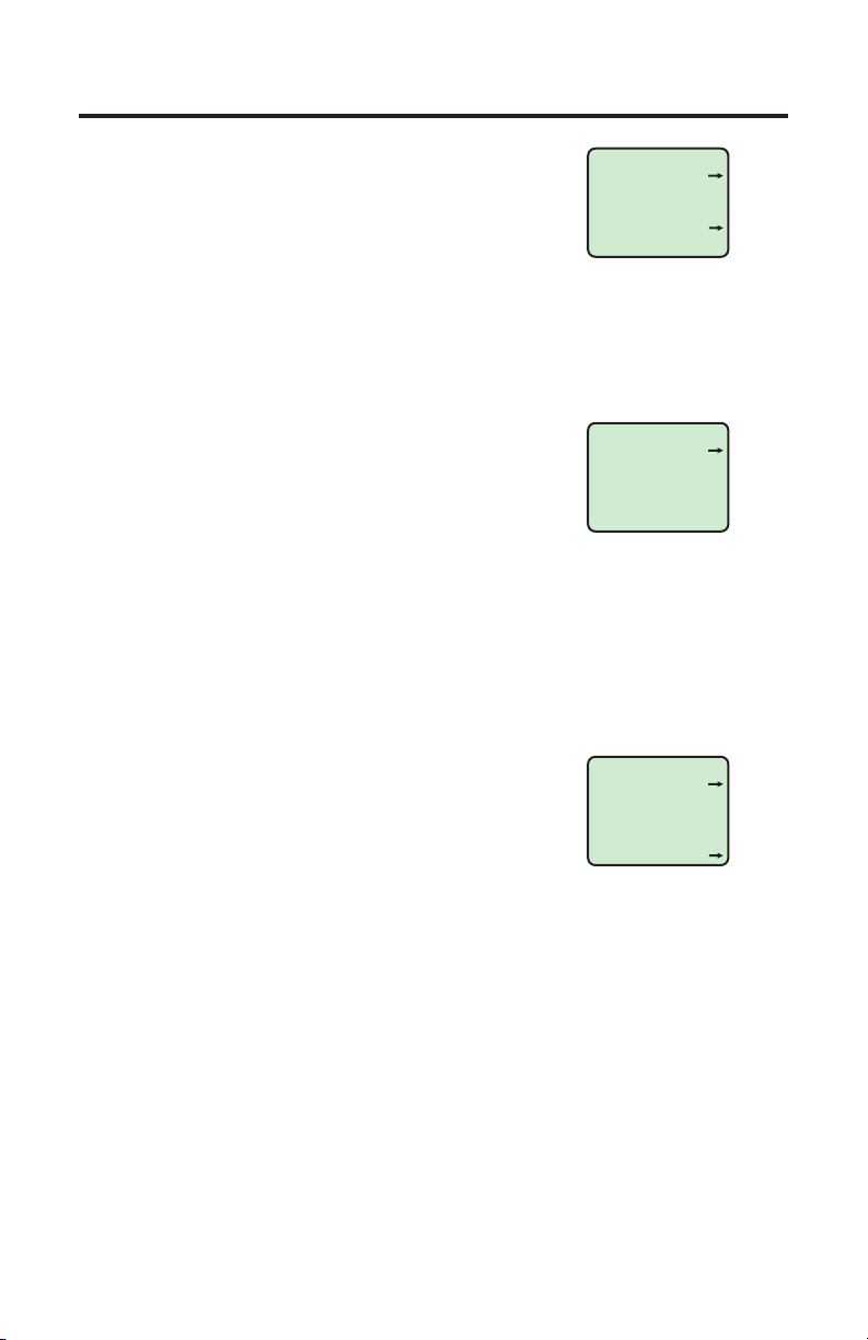
decrease the number of seconds. The number will increase to a maximum
of 256 seconds and roll over to OFF. To turn off the system, set the
number to 000 or OFF.
+To exit the programming mode, press the RUN/STANDBY button and the
MODE button at the same time. The arrow next to the word PROGRAM
will disappear and an arrow will appear next to the word RUN.
øNOTE: If while in the program mode no buttons are pressed within 10
seconds, the circuitry will automatically return to the run mode.
+The TFD system . The TFD icon will blink.
The TFD system is only used on A-100N
series peristaltic pumps. The word ON will
display indicating the TFD system is
activated. No changes are necessary.
Although it is not necessary, you may press
the DIGIT button to toggle the TFD system
on and off.
+The FVS system . Press the MODE button
to enter the FVS system programming. The
FVS icon will blink. The display will
indicate the current alarm delay time setting
in seconds. (000 = OFF).
+Press and hold he DIGIT button to increase
the number of seconds of alarm delay time,
press and hold the FIELD button to
RUN
PROGRAM
STAND-BY
PRIME
MINIMUM
MAXIMUM
0
On
MODE
TFD
RUN
PROGRAM
STAND-BY
PRIME
MINIMUM
MAXIMUM
0
001
MODE
FVS
SEC
6.4 Mode 1 - Manually adjusting the output - In this mode, the pump
is turned on and off by an electronic cycle timer. The pump will energize for
the duration of the “on time” and de-energize for the remainder of the “total
time” thus completing one cycle. The cycle then repeats.
The “on time” and “total time” cycles are independently adjustable from 0.1
to 199.9 units of measure with a 0.1 unit resolution. The units of measure
can be seconds, minutes, hours or days.
Example: If the “total time” cycle is adjusted for 90 seconds and the “on
time” portion of the cycle is adjusted for 5 seconds, the pump will run for 5
seconds and turn off for 85 seconds (90 second total cycle). This cycle is
repeated until either the standby button is pressed, the cycle time is changed
or the input power is disconnected from the pump.
+Set the pump for mode 1. Press the MODE button until MODE 1 is
shown on the LCD display.
+Enter the programming mode. At the same
time, press the RUN/STANDBY button and
the MODE button. A blinking ARROW will
point to the word PROGRAM indicating the
program mode has been activated. The total
time TOT-T icon will blink. The currently
RUN
PROGRAM
STAND-BY
PRIME
MINIMUM
MAXIMUM
1
199.9
MODE
TOT-T SEC
RUN
PROGRAM
STAND-BY
PRIME
MINIMUM
MAXIMUM
1
42.5
MODE
ON-T
SEC
selected time unit icon will be displayed. The current total time setting will
be displayed and the left most (selected) digit will blink. Note: The left most
digit can be programmed from 0 - 19. The decimal is fixed and cannot be
moved.
+Pressing the DIGIT button will increase the selected digit.
+Pressing the FIELD button will select a new digit to the right or the time
unit.
+Press the DIGIT button to increase the selected digit or time unit.
+Press the MODE button to exit the total
time programming screen and enter the on
time programming screen. The ON-T icon
will blink. The currently selected time unit
icon will be displayed. The current on time
setting will be displayed and the left most
(selected) digit will blink.
+Pressing the DIGIT button will increase the selected digit.
+Pressing the FIELD button will select a new digit to the right or the time
unit.
+Press the DIGIT button to increase the selected digit or time unit.
+At the same time, press the RUN/STANDBY button and the MODE
button. A blinking ARROW will point to the word RUN indicating the run
mode has been activated.
øNOTE: If while in the program mode no buttons are pressed within 60
seconds, the circuitry will automatically return to the run mode.
Contact Closure Alarm Output - A contact closure output (3A 125VAC
relay) is provided with the FVS system. The relay can be configured for
normally open (factory default) or normally closed operation by properly
positioning the connector plug on the circuit board (see page 7).

!Enable and Program the FVS System
The FVS system must be enabled and an alarm delay time programmed.
+Set the pump for mode 0. Press the MODE button until MODE 0 is
shown on the LCD display.
+Enter the programming mode. At the same time, press the
RUN/STANDBY button and the MODE button. A blinking ARROW will
point to the word PROGRAM indicating the program mode has been
activated.
C-1100EPage 12 C-1100E Page 13
decrease the number of seconds. The number will increase to a maximum
of 256 seconds and roll over to OFF. To turn off the system, set the
number to 000 or OFF.
+To exit the programming mode, press the RUN/STANDBY button and the
MODE button at the same time. The arrow next to the word PROGRAM
will disappear and an arrow will appear next to the word RUN.
øNOTE: If while in the program mode no buttons are pressed within 10
seconds, the circuitry will automatically return to the run mode.
+The TFD system . The TFD icon will blink.
The TFD system is only used on A-100N
series peristaltic pumps. The word ON will
display indicating the TFD system is
activated. No changes are necessary.
Although it is not necessary, you may press
the DIGIT button to toggle the TFD system
on and off.
+The FVS system . Press the MODE button
to enter the FVS system programming. The
FVS icon will blink. The display will
indicate the current alarm delay time setting
in seconds. (000 = OFF).
+Press and hold he DIGIT button to increase
the number of seconds of alarm delay time,
press and hold the FIELD button to
RUN
PROGRAM
STAND-BY
PRIME
MINIMUM
MAXIMUM
0
On
MODE
TFD
RUN
PROGRAM
STAND-BY
PRIME
MINIMUM
MAXIMUM
0
001
MODE
FVS
SEC
6.4 Mode 1 - Manually adjusting the output - In this mode, the pump
is turned on and off by an electronic cycle timer. The pump will energize for
the duration of the “on time” and de-energize for the remainder of the “total
time” thus completing one cycle. The cycle then repeats.
The “on time” and “total time” cycles are independently adjustable from 0.1
to 199.9 units of measure with a 0.1 unit resolution. The units of measure
can be seconds, minutes, hours or days.
Example: If the “total time” cycle is adjusted for 90 seconds and the “on
time” portion of the cycle is adjusted for 5 seconds, the pump will run for 5
seconds and turn off for 85 seconds (90 second total cycle). This cycle is
repeated until either the standby button is pressed, the cycle time is changed
or the input power is disconnected from the pump.
+Set the pump for mode 1. Press the MODE button until MODE 1 is
shown on the LCD display.
+Enter the programming mode. At the same
time, press the RUN/STANDBY button and
the MODE button. A blinking ARROW will
point to the word PROGRAM indicating the
program mode has been activated. The total
time TOT-T icon will blink. The currently
RUN
PROGRAM
STAND-BY
PRIME
MINIMUM
MAXIMUM
1
199.9
MODE
TOT-T SEC
RUN
PROGRAM
STAND-BY
PRIME
MINIMUM
MAXIMUM
1
42.5
MODE
ON-T
SEC
selected time unit icon will be displayed. The current total time setting will
be displayed and the left most (selected) digit will blink. Note: The left most
digit can be programmed from 0 - 19. The decimal is fixed and cannot be
moved.
+Pressing the DIGIT button will increase the selected digit.
+Pressing the FIELD button will select a new digit to the right or the time
unit.
+Press the DIGIT button to increase the selected digit or time unit.
+Press the MODE button to exit the total
time programming screen and enter the on
time programming screen. The ON-T icon
will blink. The currently selected time unit
icon will be displayed. The current on time
setting will be displayed and the left most
(selected) digit will blink.
+Pressing the DIGIT button will increase the selected digit.
+Pressing the FIELD button will select a new digit to the right or the time
unit.
+Press the DIGIT button to increase the selected digit or time unit.
+At the same time, press the RUN/STANDBY button and the MODE
button. A blinking ARROW will point to the word RUN indicating the run
mode has been activated.
øNOTE: If while in the program mode no buttons are pressed within 60
seconds, the circuitry will automatically return to the run mode.
Contact Closure Alarm Output - A contact closure output (3A 125VAC
relay) is provided with the FVS system. The relay can be configured for
normally open (factory default) or normally closed operation by properly
positioning the connector plug on the circuit board (see page 7).

6.5 Mode 2 - 4-20 mA input - In this mode, the on-time of the cycle will
automatically adjust to match the received mA input value. When the mA
input value is equal to the programmed maximum, the pump will run
continuously.
Four values must be programmed:
1) ON-T = The amount of time the pump will run, per cycle, when the
minimum mA value is received. (Typically programmed to zero)
2) mA minimum = The mA input value that will result in the on time (ON-
T). (Typically programmed to 4 mA)
3) TOT-T = The total cycle time.
4) mA maximum = The mA input value that will result in the pump running
continuously.
Example:
ON-T setting = 0 seconds
mA minimum setting = 4mA
TOT-T setting = 8 seconds
mA maximum setting = 14.8mA
6
4810 12 14 16 18 20
0
2
4
6
8
Pump Run-Time (Sec.)
Milliamp input (mA)
Page 14 Page 15
+Set the pump for mode 2. Press the
MODE button until MODE 2 is shown on
the LCD display.
+Enter the programming mode. At the
same time, press the RUN/STANDBY
button and the MODE button. A blinking
ARROW will point to the word PROGRAM
indicating the program mode has been
activated. The on time ON-T icon will
blink. The currently selected time unit
+Press the MODE button to exit the on time
programming screen and enter the mA
minimum programming screen. The mA
icon will blink. A blinking ARROW will
appear next to the word MINIMUM. The
current minimum mA setting will be
displayed and the left most (selected) digit
will blink.
RUN
PROGRAM
STAND-BY
PRIME
MINIMUM
MAXIMUM
2
00.0
MODE
ON-T
SEC
icon will be displayed. The current on time setting will be displayed and
the left most (selected) digit will blink. Note: The left most digits can be
programmed from 0 - 19. The decimal is fixed and cannot be moved.
+Pressing the DIGIT button will increase the selected digit.
+Pressing the FIELD button will select a new digit to the right or the time
unit.
+Press the DIGIT button to increase the selected digit or time unit.
RUN
PROGRAM
STAND-BY
PRIME
MINIMUM
MAXIMUM
2
04.0
mA
MODE
+Pressing the DIGIT button will increase the selected digit.
+Pressing the FIELD button will select a new digit to the right.
+Press the DIGIT button to increase the selected digit.
(selected) digit will blink. Note: The left most digit can be programmed
from 0 - 9. The decimal is fixed and cannot be moved.
+Pressing the DIGIT button will increase the selected digit.
+Pressing the FIELD button will select a new digit to the right or the time
unit.
+Press the DIGIT button to increase the selected digit or time unit.
+Press the MODE button to exit the mA
minimum programming screen and enter
the total time programming screen. The
total time TOT-T icon will blink. The
currently selected time unit icon will be
displayed. The current total time setting
will be displayed and the left most
RUN
PROGRAM
STAND-BY
PRIME
MINIMUM
MAXIMUM
2
00.0
MODE
SEC
TOT-T
RUN
PROGRAM
STAND-BY
PRIME
MINIMUM
MAXIMUM
2
20.0
mA
MODE
+Press the MODE button to exit the total
time programming screen and enter the
mA maximum programming screen. The
mA icon will blink. A blinking ARROW
will appear next to the word MAXIMUM.
The current maximum mA setting will be
displayed and the left most (selected) digit
will blink.
+Pressing the DIGIT button will increase the selected digit.
+Pressing the FIELD button will select a new digit to the right.
+Press the DIGIT button to increase the selected digit.
+At the same time, press the RUN/STANDBY button and the MODE
button. A blinking ARROW will point to the word RUN indicating the run
mode has been activated.
øNOTE: If while in the program mode no buttons are pressed within 60
seconds, the circuitry will automatically return to the run mode.
C-1100E C-1100E

6.6 Mode 3 - 0-10V DC input - In this mode, the on-time of the cycle
will automatically adjust to match the received VDC input value. When the
VDC value is equal the programmed maximum, the pump will run
continuously.
Four values must be programmed:
1) ON-T = The amount of time the pump will run, per cycle, when the
minimum VDC value is received. (Typically programmed to zero)
2) VDC minimum = The VDC input value that will result in the on time
(ON-T). (Typically programmed to 0 VDC)
3) TOT-T = The total cycle time.
4) VDC maximum = The VDC input value that will result in the pump
running continuously.
Example:
ON-T setting = 0 seconds
VDC minimum setting = 0 VDC
TOT-T setting = 6 seconds
VDC maximum setting = 7.5 VDC
Page 16 Page 17
RUN
PROGRAM
STAND-BY
PRIME
MINIMUM
MAXIMUM
3
00.0
MODE
ON-T
SEC
RUN
PROGRAM
STAND-BY
PRIME
MINIMUM
MAXIMUM
3
00.0
MODE
SEC
TOT-T
+Set the pump for mode 3. Press the
MODE button until MODE 3 is shown on
the LCD display.
+Enter the programming mode. At the
same time, press the RUN/STANDBY
button and the MODE button. A blinking
ARROW will point to the word PROGRAM
indicating the program mode has been
activated. The on time ON-T icon will
blink. The currently selected time unit
+Press the MODE button to exit the on time
programming screen and enter the VDC
minimum programming screen. The VDC
icon will blink. A blinking ARROW will
appear next to the word MINIMUM. The
current minimum VDC setting will be
displayed and the left most (selected) digit
will blink.
icon will be displayed. The current on time setting will be displayed and
the left most (selected) digit will blink. Note: The left most digits can be
programmed from 0 - 19. The decimal is fixed and cannot be moved.
+Pressing the DIGIT button will increase the selected digit.
+Pressing the FIELD button will select a new digit to the right or the time
unit.
+Press the DIGIT button to increase the selected digit or time unit.
+Pressing the DIGIT button will increase the selected digit.
+Pressing the FIELD button will select a new digit to the right.
+Press the DIGIT button to increase the selected digit.
(selected) digit will blink. Note: The left most digits can be programmed
from 0 - 19. The decimal is fixed and cannot be moved.
+Pressing the DIGIT button will increase the selected digit.
+Pressing the FIELD button will select a new digit to the right or the time
unit.
+Press the DIGIT button to increase the selected digit or time unit.
+Press the MODE button to exit the VDC
minimum programming screen and enter
the total time programming screen. The
total time TOT-T icon will blink. The
currently selected time unit icon will be
displayed. The current total time setting
will be displayed and the left most
+Press the MODE button to exit the total
time programming screen and enter the
VDC maximum programming screen. The
VDC icon will blink. A blinking ARROW
will appear next to the word MAXIMUM.
The current maximum VDC setting will
be displayed and the left most (selected)
digit will blink.
+Pressing the DIGIT button will increase the selected digit.
+Pressing the FIELD button will select a new digit to the right.
+Press the DIGIT button to increase the selected digit.
+At the same time, press the RUN/STANDBY button and the MODE
button. A blinking ARROW will point to the word RUN indicating the run
mode has been activated.
øNOTE: If while in the program mode no buttons are pressed within 60
seconds, the circuitry will automatically return to the run mode.
1
023567810
0
1.5
3.0
4.5
6.0
Pump Run-Time (Sec.)
DC voltage input (VDC)
49
RUN
PROGRAM
STAND-BY
PRIME
MINIMUM
MAXIMUM
3
9.5
MODE
VDC
RUN
PROGRAM
STAND-BY
PRIME
MINIMUM
MAXIMUM
3
0.0
MODE
VDC
C-1100E C-1100E

6.7 Mode 4 - Frequency (Hz) input - In this mode, the on-time of the
cycle will automatically adjust to match the received Hz input value. When
the Hz value is equal the programmed maximum, the pump will run
continuously.
Four values must be programmed:
1) ON-T = The amount of time the pump will run, per cycle, when the
minimum hZ value is received. (Typically programmed to zero)
2) Hz minimum = The Hz input value that will result in the on time (ON-
T). (Typically programmed to 0 Hz)
3) TOT-T = The total cycle time.
4) Hz maximum = The Hz input value that will result in the pump running
continuously.
Page 18 Page 19
RUN
PROGRAM
STAND-BY
PRIME
MINIMUM
MAXIMUM
4
00.0
MODE
ON-T
SEC
RUN
PROGRAM
STAND-BY
PRIME
MINIMUM
MAXIMUM
4
08.0
MODE
SEC
TOT-T
+Set the pump for mode 4. Press the
MODE button until MODE 4 is shown on
the LCD display.
+Enter the programming mode. At the
same time, press the RUN/STANDBY
button and the MODE button. A blinking
ARROW will point to the word PROGRAM
indicating the program mode has been
activated. The on time ON-T icon will
blink. The currently selected time unit
+Press the MODE button to exit the on time
programming screen and enter the Hz
minimum programming screen. The HZ
icon will blink. A blinking ARROW will
appear next to the word MINIMUM. The
current minimum Hz setting will be
displayed and the left most (selected) digit
will blink.
icon will be displayed. The current on time setting will be displayed and
the left most (selected) digit will blink. Note: The left most digits can be
programmed from 0 - 19. The decimal is fixed and cannot be moved.
+Pressing the DIGIT button will increase the selected digit.
+Pressing the FIELD button will select a new digit to the right or the time
unit.
+Press the DIGIT button to increase the selected digit or time unit.
+Pressing the DIGIT button will increase the selected digit.
+Pressing the FIELD button will select a new digit to the right.
+Press the DIGIT button to increase the selected digit.
(selected) digit will blink. Note: The left most digit can be programmed
from 0 - 19. The decimal is fixed and cannot be moved.
+Pressing the DIGIT button will increase the selected digit.
+Pressing the FIELD button will select a new digit to the right or the time
unit.
+Press the DIGIT button to increase the selected digit or time unit.
+Press the MODE button to exit the Hz
minimum programming screen and enter
the total time programming screen. The
total time TOT-T icon will blink. The
currently selected time unit icon will be
displayed. The current total time setting
will be displayed and the left most
+Press the MODE button to exit the total
time programming screen and enter the Hz
maximum programming screen. The HZ
icon will blink. A blinking ARROW will
appear next to the word MAXIMUM. The
current maximum Hz setting will be
displayed and the left most (selected) digit
will blink.
+Pressing the DIGIT button will increase the selected digit.
+Pressing the FIELD button will select a new digit to the right.
+Press the DIGIT button to increase the selected digit.
+At the same time, press the RUN/STANDBY button and the MODE
button. A blinking ARROW will point to the word RUN indicating the run
mode has been activated.
øNOTE: If while in the program mode no buttons are pressed within 60
seconds, the circuitry will automatically return to the run mode.
Example:
ON-T setting = 0 seconds
Hz minimum setting = 0 Hz
TOT-T setting = 8 seconds
Hz maximum setting = 425 Hz
1
023567810
0
2
4
6
8
Pump Run-Time (Sec.)
Frequency input (x100)
49
1
3
5
7
RUN
PROGRAM
STAND-BY
PRIME
MINIMUM
MAXIMUM
4
425
MODE
Hz
RUN
PROGRAM
STAND-BY
PRIME
MINIMUM
MAXIMUM
4
000
MODE
Hz
C-1100E C-1100E

6.8 Mode 5 - Pulse input (Batch) - In this mode, when the total number
of accumulated pulses is equal to the programmed pulse input value (Hz) ,
the pump will run for the programmed on time.
Two values must be programmed:
1) ON-T = The amount of time the pump will run when accumulated pulses
is equal to the programmed pulse input value (Hz).
2) Hz maximum = The number of input pulses that will trigger the batch.
+Set the pump for mode 5. Press the MODE button until MODE 5 is
shown on the LCD display.
Page 20 Page 21
RUN
PROGRAM
STAND-BY
PRIME
MINIMUM
MAXIMUM
5
00.0
MODE
ON-T
SEC
+Enter the programming mode. At the
same time, press the RUN/STANDBY
button and the MODE button. A blinking
ARROW will point to the word PROGRAM
indicating the program mode has been
activated. The on time ON-T icon will
blink. The currently selected time unit
+Press the MODE button to exit the on time
programming screen and enter the Hz
(pulses per batch) programming screen.
The HZ icon will blink. A blinking ARROW
will appear next to the word MAXIMUM.
The current Hz setting will be displayed
and the left most (selected) digit will
blink.
icon will be displayed. The current on time setting will be displayed and
the left most (selected) digit will blink. Note: The left most digits can be
programmed from 0 - 19. The decimal is fixed and cannot be moved.
+Pressing the DIGIT button will increase the selected digit.
+Pressing the FIELD button will select a new digit to the right or the time
unit.
+Press the DIGIT button to increase the selected digit or time unit.
+Pressing the DIGIT button will increase the selected digit.
+Pressing the FIELD button will select a new digit to the right.
+Press the DIGIT button to increase the selected digit.
+At the same time, press the RUN/STANDBY button and the MODE
button. A blinking ARROW will point to the word RUN indicating the run
mode has been activated.
øNOTE: If while in the program mode no buttons are pressed within 60
seconds, the circuitry will automatically return to the run mode.
RUN
PROGRAM
STAND-BY
PRIME
MINIMUM
MAXIMUM
5
000
MODE
Hz
C-1100E C-1100E
6.9 Measuring the Pump’s Output - Volumetric Test.
This volumetric test will take into account individual installation factors
such as line pressure, fluid viscosity, suction lift, etc. This test is the most
accurate for measuring the injector’s output in an individual installation.
1. Be sure the Injection Fitting and Footvalve/Strainer is clean and working
properly.
2. Fill a large graduated cylinder with the solution to be injected.
3. With the pump installed under normal operating conditions, place the
suction tubing with the Footvalve/Strainer installed in the graduated
cylinder.
4. Run the pump until all air is removed from the suction line and the solution
enters the discharge tubing. If the pump does not easily prime, remove the
discharge tubing from injection fitting until the pump primes. Re-connect
the discharge tubing to the injection fitting.
5. Remove the suction tubing from the graduated cylinder and refill the
graduated cylinder if necessary. Note the amount of solution in the gradu-
ated cylinder.
6. Place suction tubing with the Footvalve/Strainer installed back into the
graduated cylinder.
7. Run the injector for a measured amount of time. A longer testing time will
produce more accurate results.
8. Remove the suction tubing from the graduated cylinder. Measure the
amount of chemical injected.
Table of contents
Other Blue-White Laboratory Equipment manuals

Popular Laboratory Equipment manuals by other brands


Thermo Scientific
Thermo Scientific HESI-II Probe user guide

Hakko Electronics
Hakko Electronics FR-860 instruction manual

Greiner Bio-One
Greiner Bio-One VACUETTE MultiMixer user manual

Fritsch
Fritsch PULVERISETTE 5 operating instructions

Velp Scientifica
Velp Scientifica DLH F201A0157 instruction manual

Scilogex
Scilogex SCI-T6-Pro user manual