Bluebird FR900 User manual

FIXED RFID READER
FR900
QUICK
GUIDE

This user manual is protected by copyright.
Copyright © 2020 Bluebird Inc. All rights reserved.
Bluebird Inc. is the designer and manufacturer of Bluebird handheld mobiles.
This manual and the programs in this device are protected under international copyright laws, and may not
be copied, distributed, translated, or removed by any means.
Registered Trademark
BLUEBIRD is an emerging global brand, striving to lead the market in performance
and mobility. Their products represent reliability, innovation, and innovative technology.
Bluebird is a registered trademark from the global brand of Bluebird Inc. and is
copyright protected.
• Bluebird and stylized Bluebird Logo are registered trademarks and symbols of Bluebird Inc.
• Adobe® is a registered trademark of Adobe Systems Inc.
• All other trademarks and copyrights are the property of their respective owners.

1
Safety Information
1 Safety Information
1.1 Symbols
This manual uses the following symbols to indicate hazards and additional information.
Symbol Name Description
Warning Indicates situations that could cause injury to yourself or others.
Caution Indicates situations that could cause damage to your device or other equipment.
Note Indicates additional information that can help you get the most out of the device.
Please read this safety precaution information carefully. Failure to follow the information provided may
result in fire, electric shock, or other property damage or bodily injuries.
1.2 Device
• Do not press the Power button on the device if the device is wet or do not touch adapter or power
cord with wet hands. There is risk of electric shock.
• Do not use your device in an explosive danger zone.
• If your device becomes wet, do not put your device in heaters, microwaves, etc. to dry it. There is a
risk of explosion or malfunction.
• Although this device is very sturdy, do not drop, hit, bend, or sit on it on purpose. It can be broken.
• Do not modify, take apart, or repair the device. Contact to your customer service center. Failure to do
so will void your warranty.
• Do not attempt to modify your hardware or software. It may cause device malfunction and void your
warranty.
• Backup the data and information from your device. Your data may be erased during repairs or
upgrades.
• Do not paint your device. It can damage your device’s exterior.
• Avoid using or storing this device at extreme temperatures. This device is designed to work at
temperatures between -10°C and 55°C (14°F and 131°F), and humidity level between 5% and 95%.

Safety Information
2
1.3 Environment
• Do not use the device while driving or operating heavy machinery. Doing so may result in death or
serious injury.
• Do not use the device in locations with combustible goods. Doing so may result in an explosion.
• Do not use the device in dusty or hot locations. Doing so may damage the device.
• Do not expose your device to direct sunlight such as on the dashboard of a car for extended periods
of time.
• Do not use the device in humid locations. Doing so may damage the device and void the warranty.
• Do not keep the device close to air conditioner vents. Corrosion within the device may occur due to
condensation from changes in temperature.
• Do not allow children to play with the device.
1.4Frequency Interference
• The device emits an electromagnetic fields. It may interfere with your medical devices.
• Do not place credit cards, phone cards, bankbook, and tickets next to the device. The magnetic field
of the device can damage their magnetic strips.

3
2.1 Package Contents
The package includes:
Power adaptor
FR900 device
Overview
2 Overview
Power Cable

Overview
4
2.2 Your Device
2.2.1 Front
2.2.2 Back
LED

Overview
5
2.2.3 Bottom of Front
GPIO
24 VDC
Antenna Ports
Ethernet
USB Host
Reset
Function
Serial
USB Device
(management)
(management)

3 Installing and Connecting
This section provides details about FR900 I/O ports and status LEDs. It also explains how to install the Reader
and connect it to your network
3.1 FR900 LED Status
Boot Complete Status
When the FR900 has finished booting, the ACTV-STAT-ERR LED will turn on three times in green.
LLRP Server Status :
Status
ACTV
STAT
ERR
Normal (not RFID Tagging)
-
GREEN
-
Initialize fail
-
RED
RED Blink
Connection or disconnection with
client
-
GREEN Blink (2 times)
-
RFID Tagging
GREEN Blink
GREEN
-
Table 3.1 LLRP Server Status LED
Image Upgrade Status :
Status
ACTV
STAT
ERR
Image upgrade
GREEN
GREEN
-
Factory Reset
GREEN
RED
-
Table 3.2 Image upgade Status LED
3.2 Installing and Connecting the Reader
The primary installation and connection steps for FR900 are:
1.Position the Reader appropriately for your environment.
2.Connect the antenna (s)to the appropriate ports on the Reader.
3.Connect power tothe Reader.
4.Connect the Reader tothe network.
5.Configure region setting on the Reader.
6.Test the Reader installation byreading tags.
3.3 Detailed Installation Procedures
This section provides the details for each installation and connection step.
3.3.1 Step 1: Position the FR900 Reader and install the Reader.
Choose a suitable location for your Reader. The device should be placed away from direct sunlight, high
humidity, extreme temperatures and sources of electromagnetic interference.
To power the reader using an external universal power supply, make sure the outlet is nearby.
6

Installing and Connecting
3.3.2 Step 2: Connect the Antenna(s) to the FR900 Reader
FR900 Reader has eight antenna ports. Each port is independent, bidirectional, and half duplex TX/
RX (monostatic).
To connect the antenna(s) tothe Reader:
1. Position each Reader antenna, keeping the following points in mind:
• Position the antenna(s) to achieve the most effective and efficient tag reads.
• Position the antenna(s) to maximize operator safety.
2. Mount the antenna(s) according to the instructions provided by the antenna manufacturer.
3. Attach the antenna cable(s) to the antenna port(s) on the Reader.
4. Finger-tighten each connection, making sure the connection is secure.
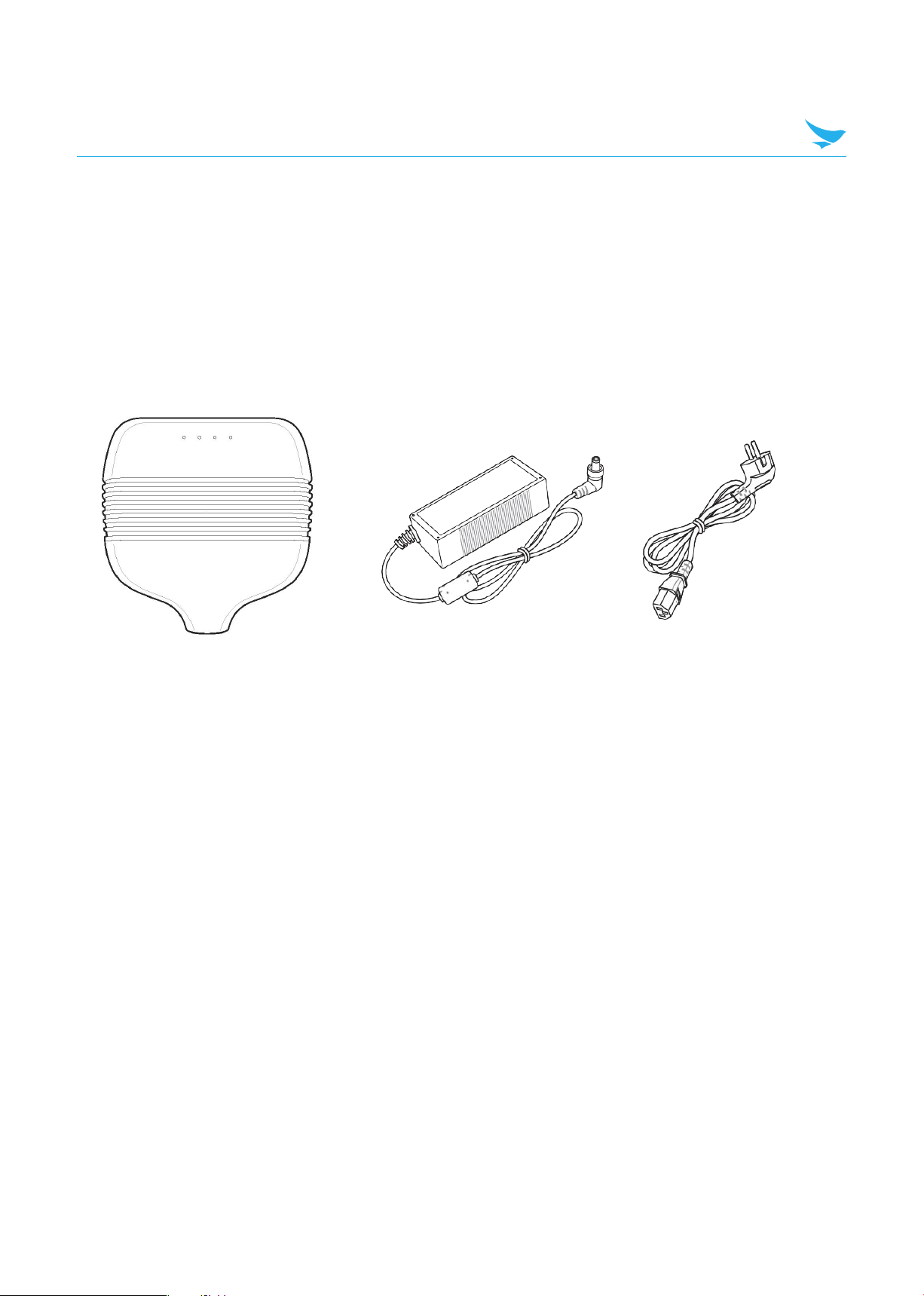
3.3.3 Step 3: Power the Reader
External universal power supply
Connect the AC power plug into a suitable 100–240 VAC, 50–60 Hz power outlet.
The Power and Status LEDs on the Reader alert you to the status.
For more information, see section 3.1 FR900 Ports and LEDs.
3.3.4 Step 4: Connect the FR900 Reader to the Network
You are now ready to connect the installed FR900 Reader to your network. You have two options:
• If your network supports DHCP, you can connect the Reader directly to your Ethernet network. After the
Reader is powered, immediately communicate with it via SSH (TCP/IP).
• If your network does not support DHCP, or if you want to connect a PC directly to the Reader via
Ethernet cable, the Reader defaults to the following fixed IP address: 169.254.1.1.
Setting
Description
Hostname
FR900-XX-XX-XX where XX-XX-XX is the last three bytes of the Reader
’
s MAC
address (which is printed on the version label attached to the Reader case).
DHCP
Default Enabled.
The Reader also reports its hostname to the DHCP server.
Note: When the reader is plugged into a network that doesn’t have a DHCP
server OR when the PC is connected directly to the Reader via Ethernet cable,
the Reader defaults to a fixed IP address (169.254.1.1).
Table 3.3: Default Network Settings
7

Installing and Connecting
To connect the FR900 Reader to the Ethernet network
Using a standard Ethernet cable, connect the RJ-45 connector on the Reader to a LAN drop
or network switch. A typical network configuration is shown in Figure 3.1.
Figure 3.1 Connecting the FR900 Reader to the Ethernet Network
To connect a FR900 Reader to your PC over a usb connection
1. Confirm that you have the latest version of Putty, a free and reliable SSH, and serial client.
Putty version 0.60 or later contains support for serial connections.
2. Use a USB A-B cable to connect your PC’s usb port on the Reader, as shown in Figure 3.2
Figure 3.2 FR900 USB Connection (management)
3. Power up the Reader and wait for the boot sequence to complete.
4. On the PC, run the Putty application and select the Serial connection option.
5. On the Putty Configuration dialog, shown in Figure 3.3, verify that Serial line to connect to is set to COMX
6. Set Speed to 115200.
7. Set Flow control to None, and then click Open.
8

Installing and Connecting
Figure 3.3 Putty Configuration Settings
8. At the BB Shell login prompt shown in Figure 3.4, log in with the Default password.
-user name: root
-password: bluebird
Figure 3.4 BB Shell login prompt
9. When the BB Shell command-line prompt displays, begin configuring the network settings for the Reader.
For more information, see Section 4.1.1 Using BB Shell to Configure Network Settings for FR900.
10. When you have completed configuration of the appropriate network settings, connect the Reader to
your Ethernet network.
9

Installing and Connecting
3.3.5 Step 5: Configure the Region Setting
Configure the region if necessary. The region can be configured using the config system region command in
the BB Shell.
Note that FCC, ETSI, Japan, and Australia Readers cannot be altered and only operate per the regulatory
laws in USA/Canada, the European Union, Japan, and Australia.
Command1
Descriptions
region
Configure the region of Reader. ASCII characters are allowed.
You must use capital letters. You can only configure the region
defined in the region table.
The config system region command allows the user to configure Reader’s region.
ASCII characters are allowed. You must use capital letters. You can only configure the region defined in the
region table.
1
KOREA
9
INDIA
17
MOROCCO
25
THAILAND
2
ETSI
10
INDONESIA
18
NEW ZEALAND
26
URUGUAY
3
FCC
11
IRAN
19
PAKISTAN
27
VENEZUELA
4
AUSTRALIA
12
ISRAEL
20
PERU
28
VIETNAM
5
BANGLADESH
13
JAPAN_1
21
PHILIPPINES
29
RUSSIA
6
BRAZIL
14
JAPAN_2
22
SINGAPORE
30
ALGERIA
7
BRUNEI
15
JORDAN
23
SOUTH_AFRICA
31
EGYPT
8
CHINA
16
24
TAIWAN
32
CHILE
Table 3.1 region table
Example :
[FR900] config system $ region KOREA
Return='0,Success'
3.3.6 Step 6: Test the Reader
Read the tag and verify that the connections and functions are correct. DemoApp, BLUEBIRD's Windows PC
test application, makes it easy to check Reader operation. Use DemoApp to configure various settings and
then run a simple inventory operatio
10

4 Configuring and Monitoring
This section provides a high-level overview of the configuration and monitoring options available for FR900
Reader
4.1 Configuring FR900 Reader
You can think of FR900 Reader configuration in two categories: configuring the device itself and configuring
the Reader’s RF behavior. This section provides the basics for each type of configuration.
4.1.1 Device Configuration
BB Shell is a proprietary command-line management interface used to configure and manage network
settings, firmware upgrades, and other device-oriented operations. This section introduces the BB Shell
commands to use to install and connect the Reader. The BB Shell Reference Manual provides full details and
syntax for all BB Shell commands.
The following procedure outlines the BB Shell commands you might need to connect the Reader to your
network.
1. Open the BB Shell console.
2. View the Reader’s current configuration settings by entering the show network summary command at
the BB Shell command prompt as shown in the following example:
> show network summary
Hostname:FR900-96-69-23
IP addr Mode:static
IP addr:192.168.50.115
Bcast:0.0.0.0
Mask:255.255.255.0
Gateway:192.168.50.1
Return='0,Success'
3. Configure the appropriate TCP/IP parameters for your environment. The applicable commands are:
Setting Hostname
> config network hostname <HOSTNAME>
Setting Static IP Address
> config network ip static <IP ADDRESS> <NETMASK> <GATEWAY>
Note: The IP address is required, however the other parameters are optional. The default value is used if an
optional parameter is omitted from the ip command.
Note: The reader MUST be rebooted for this command to take effect.
Enabling DHCP
> config network ip dhcp
Configuring NTP Servers
> config network ntp add <NTP SERVER ADDRESS>
4. After successfully configuring all required network settings, connect the Reader to the network through
the FR900 Ethernet port.
11

Configuring and Monitoring
4.1.2 RF Configuration
FR900_SDK_DEMOAPP is an example of a PC client application.
Regardless of the application you’re using, the underlying protocol is the same, Low-Level Reader Protocol
(LLRP).
LLRP is a standard, asymmetric, binary protocol used for communication between a client application and
the Reader. LLRP controls the configuration of the antenna transmit power, the receive sensitivity, the
operating Reader, and more. For more information about LLRP, see the following
documents:
•LLRP Standard This document provides the specifics ofthe LLRP standard ratified
by EPCglobal. https://www.gs1.org/sites/default/files/docs/epc/llrp_1_1-standard-20101013.pdf
Using DemoApp to Configure and Test FR900
BLUEBIRD provides a LLRP application to use to configure and test the basic RF behavior of FR900. The
DemoApp is available from the BLUEBIRD support Web site . To use DemoApp, your computer must be
running a minimum of Windows 7 and have .NET Framework 4.6.1 installed.
This section describes how to connect to and configure a Reader’s RF parameters by using DemoApp. It
also provides a high-level description of each parameter.
To configure and test a Reader by using DemoApp
1. Launch the DemoApp. The screen shown in Figure 4.1 displays.
Figure 4.1 DemoApp initial screen
12

Configuring and Monitoring
2. Click Reader Settings. The Reader Settings screen displays
Figure 4.2 DemoApp Reader Settings Connection Screen
IP : Enter the IP or hostname of the FR900
Note: You can find out the name and the IP address by using the BB Shell show network
summary command. The show network summary command provides the dynamic values that are
returned by DHCP or LLA if the current configuration is dynamic. The local hostname resolution feature
(mDNS) gives the Reader a local hostname in addition to an IP address as its network identity. On an
isolated network that lacks DNS service but that has mDNS enabled, a Reader with hostname FR900-
A1-B2-C3, for example, can be reached using FR900-A1-B2-C3.local.
Reader Mode : Specifies the rules to use for communication between the Reader and the tag.
-Default : Mode 1
-Fastest : Mode 3
Session : To control when and how often the Reader reads a tag. Each tag contains a flag that is flipped
from A to B or from B to A when it is read. The Session value controls how long the flag retains its
value before reverting back to the original tag value. Search Mode controls which flag values the
Reader reads and, in some cases, what happens to the flag value after the tag is read.
When you set Session to Dual Target, the Reader reads all the tags that have A flags.
Then, after reading the tags, the Reader flips each tag to B. When there are no more A tags to read, the
Reader reads allthe B tags, flipping each one toA after ithas been read. Itcontinues this process
back andforth from A toBandback toA.Session 1 ensures that thereisapersistence period that
prevents tags from reverting before they have all been read.
-Session 0 (Auto Toggle On) : Continue reading the same tag
-Session 1 (Auto Toggle On) : The same tag is read every 0.5 ~ 1 second
-Session 2 or 3 (Auto Toggle On) : The same tag reads only once
Population : 1 to 65535 can be set. Set to 100 if there are 100 tags in front of the antenna.
Rx Sensirivity : Max or -70 ~-30
Rx limit (RSSI) If set to -50db, RSSI below -50db will not be read.
Filter : If set to 1234, only EPCs starting with 1234 are read
Memory Bank : Reserved , EPC, TID, User (Usually use EPC)
Bit Pointer : Memory offset (bit) at filter, 32bit offser for EPC, 0bit for rest
Length : Double the length of the filter text
13

Configuring and Monitoring
Run Scenario
-Continuous : Press start button to start, continue reading until stop button is pressed
-Timed : Press start button to repeat start / stop every set time.
On time : Reading Time
Off time : Stop Time
Total Run : Repeat count
If set as below, it stops automatically after 10 times of 10 seconds Read-10 seconds stop.
Figure 4.3 DemoApp Reader Settings Timed mode
-GPI : Press the Start button to start reading when GPIX is high and to stop reading when it is low.
Set when using sensor.
Figure 4.4 DemoApp Reader Settings GPI mode
Antenna Port & Power : Power can be set for each antenna.
-Antenna Port : 1~8
-Antenna Power :10 ~ 30
The optimal setting depends on many things:
•how you are powering the Reader
•length of the cable that connects the antenna tothe Reader
•number of antennas in the area
•distance anticipated between the antenna andthe tags
Use the default value of 30 dBm for testing purposes.
14

Configuring and Monitoring
3. Test your Reader installation. Place one or more tags in the read-zone of one or more of
the attached antennas. On the DemoApp screen, click Connection and Start. Tag reads appear
under Inventory, as shown in Figure 4.5.
Figure 4.5 DemoApp Reader Settings Connection and Start
-Inventory Start / Stop
-You can check the total tag count, unique tag count, rate, and reading time.
-You can check epc information, Antenna and RSSI.
15

Configuring and Monitoring
4.2 Monitoring FR900
Use BB Shell to monitor the health and performance of the Reader when FR900 is up and running.
This section presents the primary BB Shell commands to use for viewing network and RFID statistics,
in addition to the Reader logs. For more information about these commands,
see the BB Shell Reference Manual
4.2.1 Viewing Network Parameters and Statistics
Use the BB Shell show network command to display networking parameters and statistics. When you use
this command with the parameters shown in Table 4.1, you can see the following information:
Command
Descriptions
summary
Display summary of network settings
hostname
Display hostname
dns
Display stored DNS Server list.
ip
Display IP address
mdns
Display the current state of mdns service
ntp
Display stored ntp Server list and current state.
http
Display the current state of http service.
ssh
Display the current state of ssh service
ftp
Display the current state of ftp service
Table 4.1 BB Shell Mornitoring Network Command
4.2.2 Viewing the State of the FR900 Reader
To display information about the current state of the Reader itself, use the BB Shell show system
command. When you use this command, you can see the following statistics:
Command
Descriptions
summary
Displays a summary of system info
cpu
Displays CPU information, OS version information, memory and
storage usage.
region
Displays current region and available region
Table 4.2 BB Shell Monitoring System Command
16

5Device Specification
Physical Characteristics
Dimension 253 x 254 x 56 mm
Wheight 1.5kg
Visual Status Indicators Multicolor LEDs : Power, Activity, Status, Fault, Ant 4-8
RFID Characteristics
Max Receive Sensitivity -84 dBm monostatic
Return Loss (Min) 10dB
Air Protocols ISO 18000-63 (EPC Class 1 Gen 2 V2)
Frequency (UHF Band)
US: 902-928 MHz
EU: 865-868 MHz
JP1: 916-921 MHz, JP2: 916~923 MHz
CN: 920.5-924.5 MHz
Russian Federation: 866-868 MHz
Environmental
Operating Temp -20° to +55° C / -4° to +131° F
Storage Temp -40° to +85° C / -40° to +185° F
Humidity 5-95% non-condensing
Sealing IP53
Shock/Vibration MIL-STD-810G
Performance Characteristic
Processor 600 MHz Processor
Memory 256 MB RAM / 512 MB Flash
Operating System Linux
17

Device Specification
Connectivity
Communications
10/100 BaseT Ethernet;
USB Host & Client (Type A& B); Type B: management
DB9 1ea(management),RJ-45 1ea,
HW Reset button, Function button
(Optional) Wi-Fi and Bluetooth via dongle adapter
General Purpose I/O
4 inputs, 4 outputs
optically isolated (Terminal Block)
Power Supply POE / POE+ POE(15.4W), POE+(30W)
+ 24V DC Universal Power Supply
Antenna Ports
8monostatic ports (Reverse Polarity TNC)
circular or linear polarization;
near and far field compatible
Please ask your sales representative for the specifications not listed above or for the future upgradeable
specifications
18
Table of contents