Bluefin LED GW20IFM User manual

1
Bluefin LED Underwater lights.
GW20IFM/GW48CCIFM Installation manual.
Thank you for choosing Bluefin LED underwater lights, our products have been designed and tested
to ensure optimum performance and longevity is maintained.
All Bluefin Led lights are water tested so please be aware there may be moisture present on the light.
This light is designed for use on fibre glass hulls only and not to be mounted to any Metal hull or
your warranty will be void. If you are mounting to a Metal hull boat a Delrin isolation sleeve can be
purchased.
Please ensure that your product is installed as per our instructions below, failure to do so may
invalidate your warranty.
If you are installing a GW48CCIFM please refer to the Driver instructions for electrical installation.
Specification: electrical/fuse ratings
Voltage
Current
Fuse rating
Great White
GW20IFM
24V only (Absolute min of
19V under load @ light).
24v-5.1
8amp
Warnings:
•Do not attempt to install the lights whilst the boat is in the water.
•Ensure that the correct voltage is used for the light.
•Ensure that an in line fuse is installed with the correct fuse rating per the light installed.
•Ensure that the supplied gel connector is used to make a watertight connection or your
warranty will be Void.
•Do not remove the inline HYDRO LOCK or your warranty will be void.
•Do not hold the light by the cable.
•Do not use abrasives on the lenses.
•Do not stare into the LED light at close proximity
•Lights must be mounted a minimum of 300mm from any Anodes.
•Do not mount lights directly underneath Anodes.
•Do not bond directly to Anodes.
•Only bond to the vessels DC bonding system & ensure all connections are in perfect
condition & are regularly checked.
•When mounting on any type of conductive surface or hull material full electrical isolation
between the light & mounting surface must be provided & maintained at all times
throughout the lights life.
•Failure to adhere to any of these requirements will invalidate warranty.
•As Galvanic currents & corrosion are external factors any type of damage caused by galvanic
affects are not covered by BluefinLEDs warranty policy.
Tools required for installation:
•101mm(4”) hole saw
•Drill
•Marine sealant 3M 5200/4000UV, Sika flex 291i or equivalent (do not use 3M 4200)
Installation:
For optimum affect effect the light should be positioned between 8-12” (200-300mm) below the
water line and at a 90 deg angle. Recommended spacing from 3-3”(1mtr) to 5-11” (1.8mtrs) between
the lights.
2
Drill a 101mm (4”) hole for the light access through the hull, ensuring that there are no obstructions
internally in the hull.
Key the area to where the light is to be mounted with abrasive sand paper to ensure there is a clean
area for the marine sealant to bond too.
Apply marine sealant to the rear of the light on the circumference of the light and around the base of
the tube to ensure a complete continuous bead of sealant is applied in both areas. (See fig 2)
Feed the light through the hole and clamp internally in the hull using the clamping ring and washer
supplied ensuring a tight fit using nuts and bolts supplied. (See fig 3 and 4)
Wipe off any excess sealant and ensure the light is seated correctly without any gaps in the sealant.
(It is good practice to have excess marine sealant to clean off as this can ensure that there is a water
tight seal to the hull)
Electrical connection:
Ensure you use the IP68 GEL CONNECTOR supplied to connect to the boats wiring or you Warranty
will be void (fig 6/7).
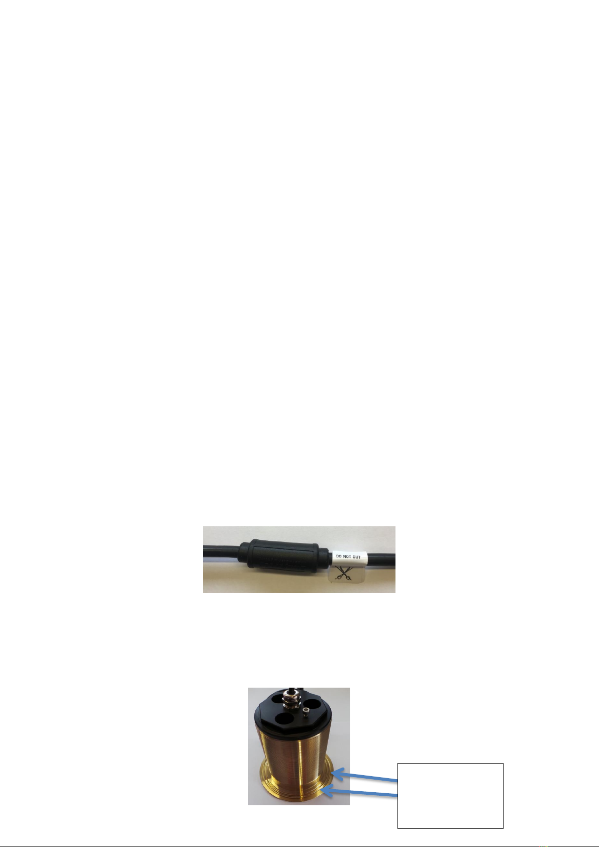
You will notice an inline HYDRO LOCK attached to your cable (Fig 1). If this guard is removed you
warranty will be void
It is advised that if installing GW16 models no more than 8 lights should be installed on your low
voltage system.
If installing more than 8 GW16 models we suggest using our Mains Upgrade Power Supply (contact
your local Bluefin Led dealer for further information)
It is advised that if installing GW20 or GW48CC Models no more than 6 lights should be installed on
your low voltage system.
If installing more than 6 GW20 or GW48CC models we suggest using our Mains Upgrade Power
Supply (contact your local Bluefin Led dealer for further information)
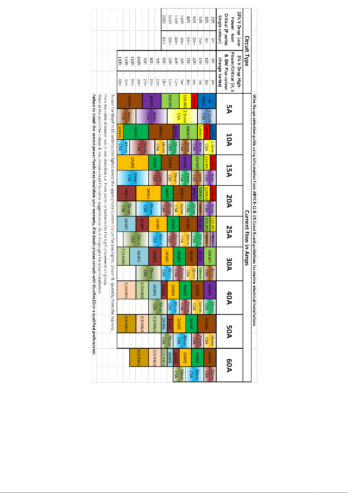
Care should be taken when planning your electrical feeds/cables to the lights so as to ensure voltage
drop between the batteries or power supply is minimised, on 12V systems this is especially important
as the lower system voltage means a high current requirement which in turn means the potential for
more voltage drop in the cable runs & connections.
If the cable gauge & connections are not sufficient for the lighting load attached you may experience
incorrect operation of the lights & intermittent illumination as the supply dips below specification.
Please see the wire gauge guide attached to the instruction manual.
For help with calculations always consult with a qualified professional or contact Bluefin LED directly.
Fig 1
Attach the light cable to the VDC power on the boat ensuring that you use the in line fuse supplied
connected to the positive(red) wire, ensure that you use the heat shrink provided to create a water
tight fit into the fuse holder. (See fig 5)
Ensure that an earth bond cable is attached to the earth bolt on the locking ring and is attached to
the earth bonding system on the boat. (See fig 3)
Fig 2
Apply Sealant
around these
grooves and around
the tube

3
Fig 3
Fig 4
Fig 5
Fig 6 showing how the Gel connector is wired up.
Fig 7 showing how the finished Gel connector should look when finished.
Ensure that the black outer sheath is inside the gel connector.
The IP68 GEL CONNECTOR MUST BE INSTALLED CORRECTLY OR YOU WARRANTY WILL BE VOID.
Fig 6
Fig 7
Bluefin Led Underwater lights.
LM48CC Driver Installation manual.
Earth bond
nut and
bolt
Image showing how to
wire the Gel Connector to
the light and Fuse holder
Please use fuse
instructions within the
manual to wire the fuse
Power
In
from
boat
power
Locking ring
showing nuts and
bolts assembled
Positive wire
from Light
Light
cable
Heat shrink for
water tight seal to
the fuse holder
Fuse holder
Crimps for
positive wires
(ensure that these
are mounted into
the holder before
they are crimped)
Picture showing
example of
clamping ring and
washer
assembled
Negative wire
to boat power
in
Heatshrink
Please ensure
outer sheath is
inside the gel
box
4
Thank you for choosing Bluefin LED underwater lights, our products have been designed and tested
rigorously to ensure the optimum performance and longevity.
Please ensure that your product is installed as per our instructions below, failure to do so may
invalidate your warranty.
Specs: electrical/fuse ratings
Voltage
Current
Fuse rating
LM48CC Drivers
24V only
24V-6.5
8amp
Warnings:
•Do not attempt to install the lights whilst the boat is in the water.
•Ensure that the correct voltage is used for the light and Driver.
•Ensure that the in line fuse is installed with the correct fuse rating per the Driver installed.
•Ensure that the supplied gel connector is used to make a watertight connection or your
warranty will be Void.
•If you wish to connect your Colour change lights and drivers to your own DMX Controller
please contact BluefinLED beforehand for further advise.
Installation:
Electrical connection:
•Ensure that the supplied gel connector is used to make a watertight connection or your
warranty will be Void (see fig 6/7)
•Attach the Driver power cable to the VDC power on the boat ensuring that you use the in line
fuse supplied connected to the positive(red) wire, ensure that you use the heatshrink
provided to create a water tight fit into the fuse holder. (see fig 2)
•Plug the Light cable connector to driver as per Fig 1 aligning the white lines on the
connectors to ensure the connector pushes home correctly.
•Plug the DMX controller cable (if supplied fig 3) into the first driver DMX IN connector as per
Fig 1.
•Plug the DMX Interlink cable (Fig 4) into the DMX OUT connector on the first driver Fig 1.
•You can now daisy chain the drivers using the DMX Interlink cables going from the OUT DMX
to the IN DMX on the next driver.
•When completing a circuit you must plug the DMX Terminator plug (Fig 5) into the last
drivers DMX OUT to complete the circuit.
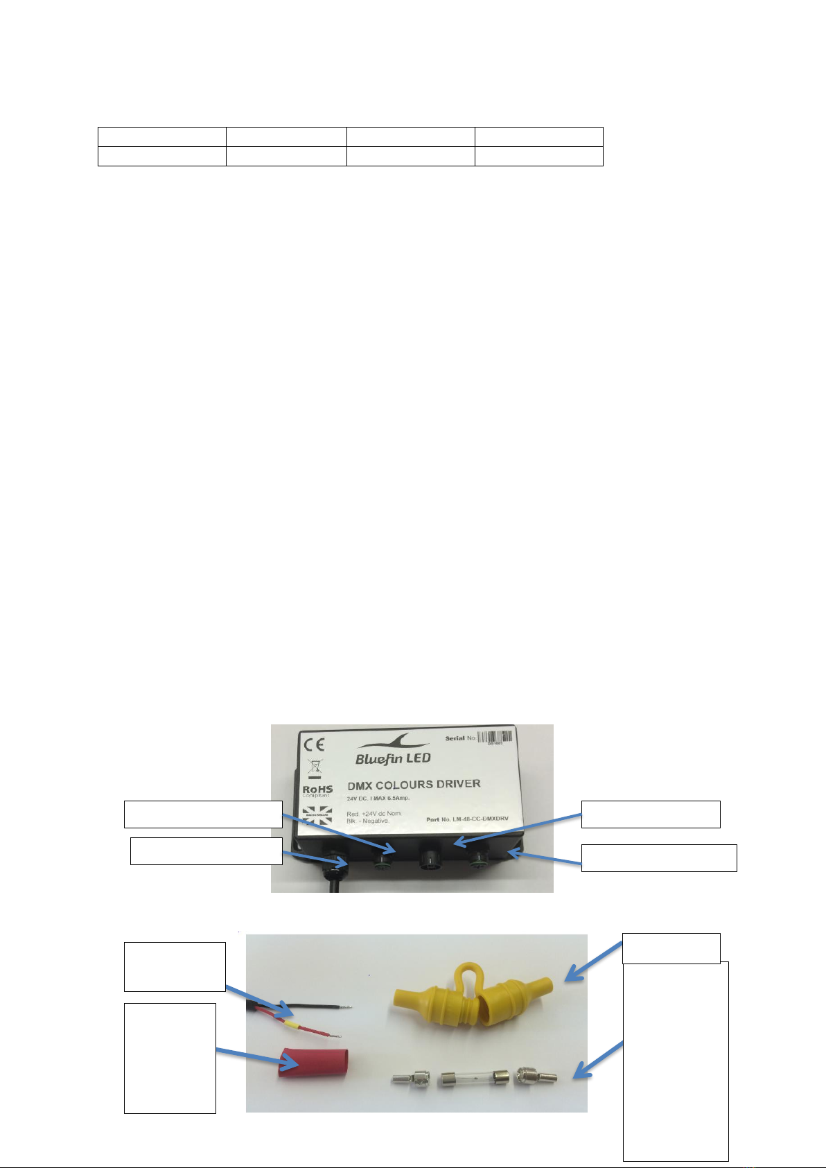
Fig 1 (Driver)
Fig 2 (Fuse connection)
Crimps for
positive
wires (ensure
that these
are mounted
into the
holder
before they
are crimped)
Heatshrink
for water
tight seal
to the fuse
holder
Fuse holder
Positive wire
from Driver
Light cable connector
24VDC Power cable
DMX IN Connector
DMX OUT Connector

5
Fig 3 (DMX Controller cable)
Fig 4 (DMX Interlink cable)
Fig 5 (DMX Terminator)
Fig 6 showing how the Gel connector is wired up.
Fig 7 showing how the finished Gel connector should look when finished.
Ensure that the black outer sheath is inside the gel connector.
The IP68 GEL CONNECTOR MUST BE INSTALLED CORRECTLY OR YOU WARRANTY WILL BE VOID.
Fig 1
Fig 2
Testing:
Test the light before installation ensuring that you use the correct voltage and the light is illuminated
correctly.
Image showing how to
wire the Gel Connector to
the light and Fuse holder
Please use fuse
instructions within the
manual to wire the fuse
Power
In
from
boat
power
Driver
cable
Negative wire
to boat power
in
Heatshrink
Please ensure
outer sheath is
inside the gel
box
6
After installation ensure again that the light is illuminated correctly before the boat goes back into
the water and you remove the lens label.
After you boat goes back into the water check internally for water tightness around where the light is
installed.
The light has internal indicator Led’s for fault finding, these are as follows:
•Over voltage will flash red.(check the voltage to the light)
•Under voltage will show a constant red. (check the voltage to the light)
•Over temperature will show amber.(allow the light to cool down and check if submerged)
Maintenance:
Regularly check the installation for water tightness
Only clean the light with a soft bristle brush
Warranty:
For any warranty issues please contact your point of sale retailer or go to www.bluefinled.com for
further advice.
Bluefin LED LTD warrants the lights/hardware it manufactures and produces to be free from
defects in workmanship and materials for a period of two years, starting from the date of original
purchase, as recorded on the sales receipt.
The warranty is non-transferable and limited to the original purchaser of the product. During the
two year warranty period Bluefin LED will repair or replace the defective item (at its option) at no
additional charge on a “like for like” basis. Products either repaired or replaced under this
warranty shall only be warranted for the unexpired portion of the warranty applying to the original
product(s).
Bluefin LED is not responsible for labour charges to remove or replace lights or for haul-out fees.
No refunds will be given.
This limited warranty does not extend to any products which have been damaged as a result of
misuse, abuse, improper installation/modification, galvanic corrosion, failure to follow and adhere
to installation instructions provided by Bluefin LED, improper shipping, neglect, damage caused
by disasters such as fire, flood, lightning “acts of god”, installation by unqualified personnel.
Do not attempt to disassemble the light without Bluefin LED advice.
Installer please ensure that the SERIAL NUMBERS of the lights are written below and the
manual is handed over to the end user.
Please make a note of the serial numbers of the lights here.
SERIAL NUMBERS
Bluefin LED
Cottage Farm, Cottage Lane,
Norton Juxta Twycross, Atherstone. CV9 3QH
Service - Tel: 01827 880450 Email: mark.branson@bluefinled.com
Administration - Tel: 01827 880450 Email: samantha.barrie@bluefinled.com
Registered Address: Square Rig Limited, t/a Bluefin LED, Cottage Farm, Cottage Lane, Norton Juxta Twycross, Atherstone, CV9 3QH
Company Registration Number: 08871451 VAT Number: 179 2690 64
7
This manual suits for next models
1
Table of contents
Other Bluefin LED Underwater Lighting manuals

Bluefin LED
Bluefin LED Piranha P3 User manual

Bluefin LED
Bluefin LED Mako M12IFM24V User manual

Bluefin LED
Bluefin LED Piranha P6N User manual

Bluefin LED
Bluefin LED OR16 User manual

Bluefin LED
Bluefin LED ORCA OR20CC User manual

Bluefin LED
Bluefin LED H16 User manual

Bluefin LED
Bluefin LED Mako M12IFM12V User manual

Bluefin LED
Bluefin LED Firefly FF User manual

Bluefin LED
Bluefin LED P24 User manual

Bluefin LED
Bluefin LED MR48CCTH User manual


