6
Installation and Operation
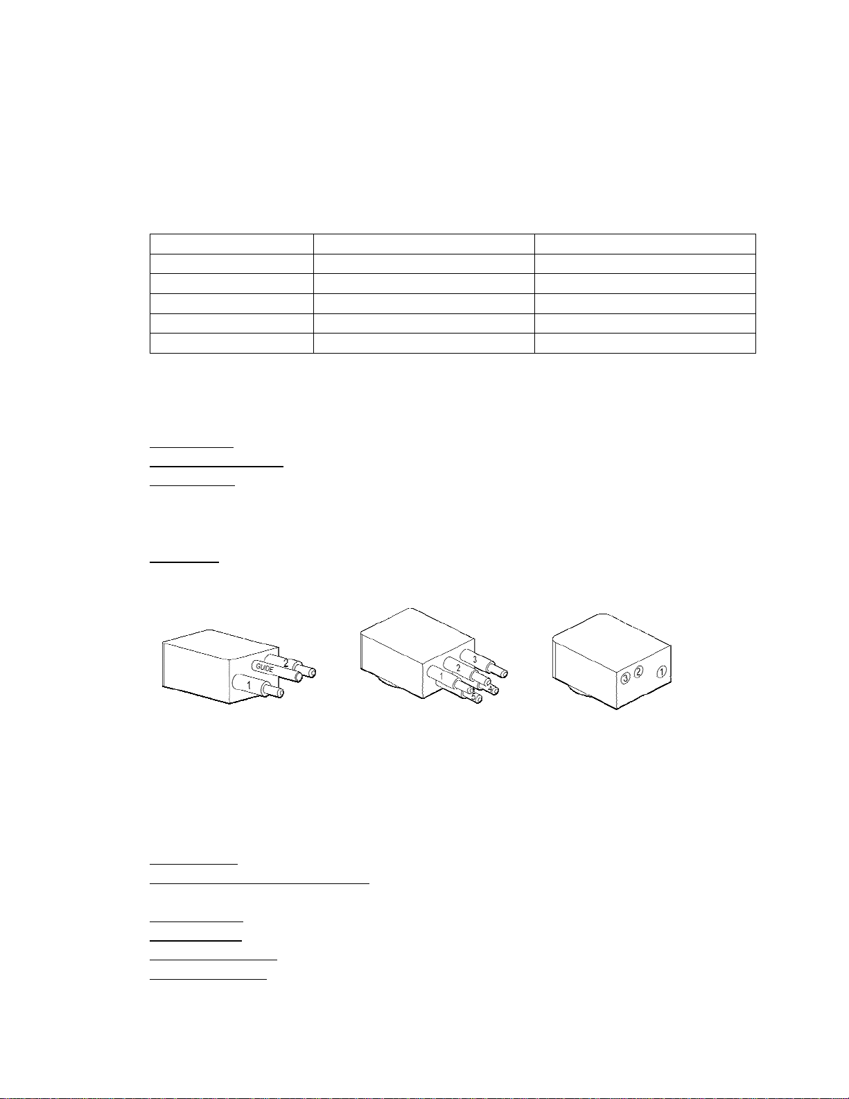
Assembly:
1. Remove the protective connector cover on the ballast end-cap.
2. Plug the lighthead to ballast interconnect cable into the lighthead.
3. Plug the other end of the interconnect cable into the ballast output connector.
4. Plug the ballast power cable into the ballast input connector.
5. Reinstall the protective connector cover on the ballast end-cap.
6. Connect the ballast power cable to the power source through a proper on/off switch and
circuit protector (fuse/circuit breaker).
7. The light is now ready to test.
NOTE - DC INPUT: The input is not polarity sensitive (either pin can be plus and the other
minus). The input is less than 5 amps when running but the surge current at turn on can be as
high as 30 amps.
NOTE - AC INPUT: The input is less than 6 amps when running but the surge current at turn on
can be as high as 35 amps.
Warning: Whenever AC power is used in the vicinity of water, we strongly recommend that a
Ground Fault Interrupt (GFI) or other protective device is utilized to minimize the chance of
electric shock due to a short circuit.
Operation:
Apply power to the ballast to turn on the light. At turn on there is a delay of approximately 3
seconds before the lamp will strike. After the lamp strikes it goes through a warm up stage that
takes 60 to 90 seconds to complete.
Warning: The lighthead must be submerged in water when running or it will overheat and
cause damage to the seals and dome. The ballast can be run dry (in air) for up to 15 minutes
without causing damage.
Warning: HMI lights emit a significant amount of UV radiation that can cause sunburn and
damage to the eyes. The borosilicate glass dome filters out some of the harmful UV when the
lamp is installed in the lighthead. Do not run the lamp with the dome removed.
To turn off the light, remove power to the ballast.
To restart the light wait 10 seconds and then re-apply power to the ballast. There will be a delay
of approximately 3-5 seconds before the lamp will restrike. The lamp does not require the full
warm up cycle as it is still warm but it could be as much as 30 seconds until the lamp is at full
color temperature and light output.
HMI lamps start best when cold. If a lamp fails to restrike, allow several minutes for the lamp to
cool and then attempt to strike the lamp again. Though immediate restriking of the lamp is
supported, the recommended practice is to allow at least two minutes between restrikes and
longer periods when possible.