2-4
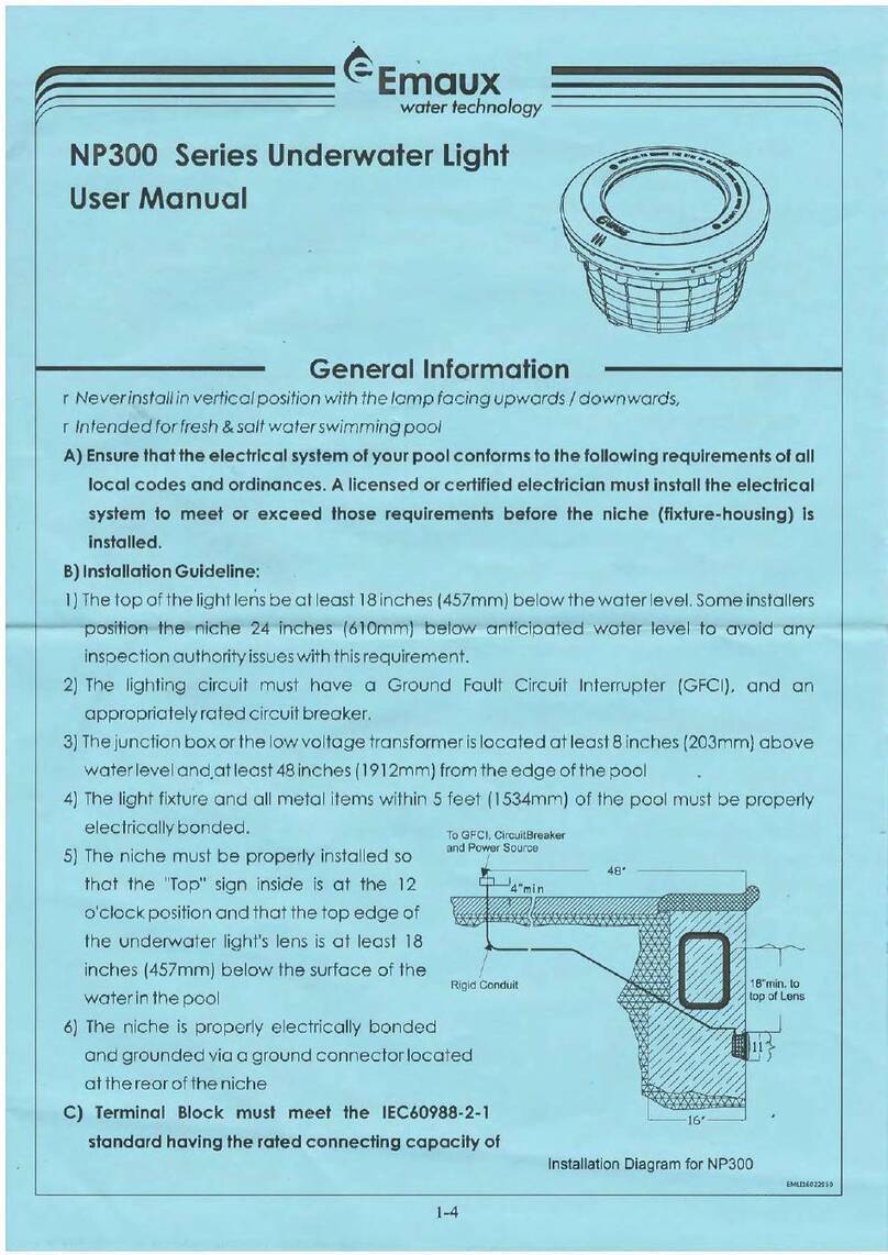
A) Preparatory steps which must be completed by the electrician before light
3-4
Figure 4.
Figure 3.
Figure 2.
DO NOT MO UNT ON:
REVER SE RADI US
SURFA CE
IRREG ULAR OR
UNEVE N SURFA CES
DO MOUN T ON:
FLAT
SURFA CE
WALLS W ITH NO TI GHTER
THAN 6 FT . RADIU S AS
VIEWE D FROM TO P
X
OPEN
POSIT ION
LOCK
POSIT ION
OPEN
POSIT ION
LOCK
POSIT ION
Figure 5.
is installed, see Figure 1.
350CM MIN.
WATER LEVEL
6.6CM
23.0CM
RIGID CONDUIT
TO POWER SOURCE;
FEED PARAFFIN
CONCRETE MUST BE CUT BACK
AROUND NICHE TO ALLOW FOR
A COMPACT PLASTER SEAL
45CM MIN. FROM WATER LINE
TO THE EDGE OF THE FACE PLATE
Figure 1.
FOR FIBREGLASS POOL, PRE-FAB
MODULAR POOL AND VINYL LINER POOL
FOR FIBREGLASS POOL,
PRE-FAB MODULAR POOL
AND VINYL LINER POOL
FOR CONCRETE POOL
Figure 0.
C. Winterizing: The luminaire should be left in place for winterization.
B) Perform the following steps after the electrical system requirements are met.
1 Ensure that the electrical system and its wiring for the pool conform to the requirements of your
govenment or your local authorities. The installation of the Underwater Light should only be
performed by a licensed electrician.
a) The junction box, or the low voltage transformer for 12 volt Underwater Light model is to be located
at least 350cm from the edge of the pool, see Figure 1.
b) The junction boxes shall not be installed in zones 0,1 and 2,where permitted for SELV circuits.
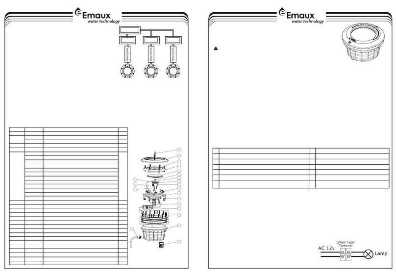
c) Terminal blocks must meet the IEC60988-2-1 standard having the rated connecting capacity of
1.5mm2 use of screw-type terminal at least 25A rated current , mounted on junction boxes inside.
See Figure 0
d) The light fixture and all metal parts that are within 350cm of the pool must be properly protected
with non-ductile materials and that the connections must be waterproof.
e) The mounting bracket must be properly installed so that the top edge of the Underwater Light lens
is at least 45cm below the surface of the water in the pool, see Figure 1.
2) Consult the local government Building Department to be certain that the pool's electrical system
meets all applicable requirements.
)
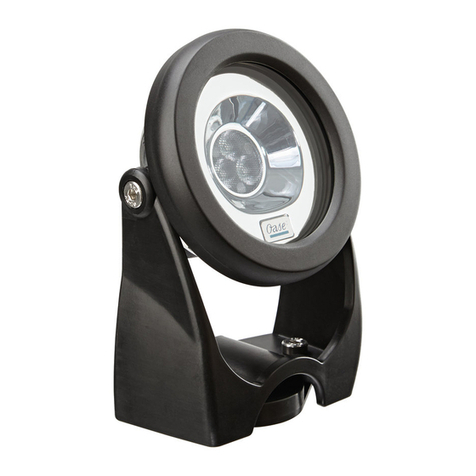
1) Locate position on a vertical wall where light is to be installed. The top of the light lens must be
45cm below normal water level, and maximum depth for luminaire is 2.5m, see Figure 1.
2) Connect conduit to midst of Mounting Spacer (left of Bracket), see Figure 2.
3) If pool surface is to be plastered, you must allow proper concrete cutback for plaster thickness.
Finish concrete surface must be flush with Mounting Spacer. CAUTION: Finish area surrounding
Mounting Spacer MUST be flat and flush with the face of Mounting Spacer, this ensures a snug fit
between light and wall, see Figure 3.
4) After pool surface is finished, trim the Conduit.
5) Wrap a length of the cord up to a maximum of 3.5mt long on the back of the light assembly.
6) Connect cord electrical wires at Junction box, through Conduit, be careful not to pull the 75mm-
80mm of slack cord at the luminair through the conduit when connecting the wires.
7) Connect all wires to the corresponding circuit wires in the junction box and feed paraffin.
8) Secure the junction box cover in place.
9) To check for proper operation, turn on main switch or circuit breaker.
10) Rotating Locking System ensures light is secured to bracket, see Figure 4.
11) Before operating the lamp for more than 10 seconds fill pool until the pool luminair is completely
submerged in the water.
12 ) The flexible cable of this luminaire cannot be replaced, if the cord is damaged, the luminaire shall
be destroyed.
INSTALLATION

