Tritech P-Sea User manual

P-Sea Underwater Console
0744-SOM-00002-1 1 © Tritech International Ltd.
P-Sea Underwater Console
Product Manual
0744-SOM-00002-1

P-Sea Underwater Console
0744-SOM-00002-1 2 © Tritech International Ltd.
© Tritech International Ltd
The copyright in this document is the property of Tritech International Ltd. The document is supplied by Tritech International Ltd on
the understanding that it may not be copied, used, or disclosed to others except as authorised in writing by Tritech International Ltd.
Tritech International Ltd reserves the right to change, modify and update designs and specifications as part of their ongoing
product development programme.
All product names are trademarks of their respective companies.

P-Sea Underwater Console
0744-SOM-00002-1 3 © Tritech International Ltd.
Table of Contents
Help & Support ........................................................................................................... 5
Warning Symbols ........................................................................................................ 6
1. Introduction ............................................................................................................. 7
2. Specification ........................................................................................................... 8
2.1. Dimensions .................................................................................................. 8
2.2. Physical and Electrical Properties ................................................................. 9
3. Getting Started ...................................................................................................... 10
3.1. Plugging in the cables ................................................................................ 10
3.2. First power on ............................................................................................ 14
4. Installation ............................................................................................................ 17
4.1. Power Connector ....................................................................................... 17
4.2. Sonar Connector ........................................................................................ 17
4.3. Serial Connectors ....................................................................................... 18
4.4. USB Connector .......................................................................................... 19
5. Basic Operation .................................................................................................... 20
5.1. Activity Indicators ....................................................................................... 20
5.2. User Controls ............................................................................................. 20
5.3. Recording Data .......................................................................................... 22
5.4. Transferring Data ....................................................................................... 23
6. Advanced Operation .............................................................................................. 24
6.1. User Screen ............................................................................................... 24
6.1.1. Overview ......................................................................................... 24
6.1.2. Online Button .................................................................................. 25
6.1.3. Record Button ................................................................................. 26
6.1.4. Player Controls ................................................................................ 26
6.1.5. Capture Screen ............................................................................... 28
6.1.6. Record Video .................................................................................. 29
6.1.7. Acoustic Zoom button ...................................................................... 29
6.1.8. CHIRP button .................................................................................. 30
6.1.9. Invert Display (Up/Down) ................................................................. 30
6.1.10. Flip Image (Left/Right) ................................................................... 30
6.1.11. Rotate Image ................................................................................. 31
6.1.12. Draw Grid ...................................................................................... 31
6.1.13. Zoom Button .................................................................................. 31
6.1.14. Filter Selector ................................................................................ 32
6.1.15. Sound Velocity Indicator ................................................................. 32
6.1.16. Palette Selector ............................................................................. 32
6.1.17. Gain Control .................................................................................. 33
6.1.18. Range Control ............................................................................... 33
6.1.19. Indicators ...................................................................................... 33
6.1.20. Sonar Swathe ................................................................................ 33
6.1.21. Measurements ............................................................................... 34
6.1.22. Warnings ....................................................................................... 34
6.2. Advanced Screen ....................................................................................... 35
6.2.1. System Data ................................................................................... 36
6.2.2. Configuration Options ...................................................................... 36
6.2.3. Application Settings ......................................................................... 39
6.2.4. Filter Settings .................................................................................. 41
6.2.5. Device Network Settings .................................................................. 42
6.2.6. Distance Marker .............................................................................. 43
6.2.7. Target Tracking ............................................................................... 44
6.3. Serial Data Input ........................................................................................ 47
6.3.1. Sonars & Sensors ........................................................................... 48
6.3.2. Gemini Hub ..................................................................................... 49
6.3.3. COM Ports ...................................................................................... 50

P-Sea Underwater Console
0744-SOM-00002-1 4 © Tritech International Ltd.
6.3.4. Aux Power ...................................................................................... 51
6.4. Gemini Firmware updates ........................................................................... 52
6.5. Multiple Head Operation ............................................................................. 53
6.6. Offline Mode .............................................................................................. 56
6.7. Automatic Online ........................................................................................ 56
6.8. Settings Files ............................................................................................. 56
6.9. Keyboard Shortcuts .................................................................................... 57
7. Maintenance ......................................................................................................... 58
7.1. General Guidance ...................................................................................... 58
7.2. Pre-Dive checks ......................................................................................... 58
7.3. Post-Dive checks ....................................................................................... 58
8. Troubleshooting .................................................................................................... 59
A. MetalSub Batteries ............................................................................................... 61
B. Cables .................................................................................................................. 62
C. Setting the computer IP address in Windows® XP ................................................. 64
D. Setting the computer IP address in Windows® 7 or Windows® 10 ........................... 66
E. Setting the Gemini Device IP Address in Gemini Software ...................................... 68
F. Gemini Software String Decode ............................................................................. 69
G. Gemini Software String Encode ............................................................................ 71
Glossary ................................................................................................................... 72

P-Sea Underwater Console
0744-SOM-00002-1 5 © Tritech International Ltd.
Help & Support
First please read this manual thoroughly (particularly the Troubleshooting section, if present).
If a warranty is applicable, further details can be found in the Warranty Statement, 0080-
STF-00139, available upon request.
Tritech International Ltd can be contacted as follows:
Mail Tritech International Ltd
Peregrine Road
Westhill Business Park
Westhill, Aberdeenshire
AB32 6JL, UK
Telephone ++44(0)1224 744 111
Fax ++44(0)1224 741 771
Email [email protected]
Website www.tritech.co.uk
Prior to contacting Tritech International Ltd please ensure that the following is available:
1. The Serial Numbers of the product and any Tritech International Ltd equipment connected
directly or indirectly to it
2. Software or firmware revision numbers
3. A clear fault description
4. Details of any remedial action implemented
Contamination
If the product has been used in a contaminated or hazardous environment you
must de-contaminate the product and report any hazards prior to returning the
unit for repair. Under no circumstances should a product be returned that is
contaminated with radioactive material.
The name of the organisation which purchased the system is held on record at Tritech
International Ltd and details of new software or hardware packages will be announced at
regular intervals. This manual may not detail every aspect of operation and for the latest
revision of the manual please refer to www.tritech.co.uk
Tritech International Ltd can only undertake to provide software support of systems loaded
with the software in accordance with the instructions given in this manual. It is the customer's
responsibility to ensure the compatibility of any other package they choose to use.

P-Sea Underwater Console
0744-SOM-00002-1 6 © Tritech International Ltd.
Warning Symbols
Throughout this manual the following symbols may be used where applicable to denote any
particular hazards or areas which should be given special attention:
Note
This symbol highlights anything which would be of particular interest to the reader
or provides extra information outside of the current topic.
Important
When this is shown there is potential to cause harm to the device due to
static discharge. The components should not be handled without appropriate
protection to prevent such a discharge occurring.
Caution
This highlights areas where extra care is needed to ensure that certain delicate
components are not damaged.
Warning
DANGER OF INJURY TO SELF OR OTHERS
Where this symbol is present there is a serious risk of injury or loss of life. Care
should be taken to follow the instructions correctly and also conduct a separate
Risk Assessment prior to commencing work.

P-Sea Underwater Console
0744-SOM-00002-1 7 © Tritech International Ltd.
1. Introduction
The P-Sea Underwater Console is a subsea computer system designed to provide divers
with a real time interface to Tritechs range of imaging Sonar products.
Power is supplied to the P-Sea via subsea battery packs, capable of providing +24V DC and
will consume 30W (excluding any power required for connected sonars or third party sensors)
Sensors and other external peripherals can be interfaced to the P-Sea through its two serial
ports (one set to RS232 and the other set to RS485). A USB port is also provided to aid the
transfer of logged data from the P-Sea to compatible storage devices.
The RS232 ports are capable of supporting up to 115k2 Baud and can provide +12V to +36V
at 1A to power additional devices.
The USB ports support USB 2.0 devices and are also backwards compatible with older USB
devices which support the USB 1.1 specification.
The P-Sea runs a Windows® 10 embedded OS and is has been optimised to run the Gemini
Software for display and data logging. The visual display is in the form of a 7” LCD display
with a native resolution of 1024 x 768.
The processor in the P-Sea is an Intel Atom CPU with 2Gb RAM. An Internal SSD provides
a dedicated storage capacity of 80Gb.

P-Sea Underwater Console
0744-SOM-00002-1 8 © Tritech International Ltd.
2. Specification
2.1. Dimensions

Specification P-Sea Underwater Console
0744-SOM-00002-1 9 © Tritech International Ltd.
2.2. Physical and Electrical Properties
Physical Properties
Property Details
Materials Aluminium ACP 5080 (Housing)
Tempered glass (Screen)
Finish Hard Anodised Black
Weight 5.98kg (2.2kg in water)
Depth rating 50m
Temperature range -10 to +40°C (-20 to +60°C in storage)
Connectors MKS(W)-307-FCR
IE55-1206-BCR
IE55-1204-BCR
Electrical and Computer Properties
Property Details
Power requirement 20 to 36VDC
Power consumption 30W (excluding external equipment)
Computer Processor AtomTM E3800
Installed RAM 2Gb
Internal Storage 120Gb (80Gb available for logging)
Display Size 7"
Display Resolution 1280 x 1024

P-Sea Underwater Console
0744-SOM-00002-1 10 © Tritech International Ltd.
3. Getting Started
The P-Sea has been designed with speed of deployment in mind and can quickly be rigged
up for use.
The following instructions assume that the P-Sea is being fully deployed with a Gemini 720is
Sonar, MetalSub battery packs and no Serial port devices.
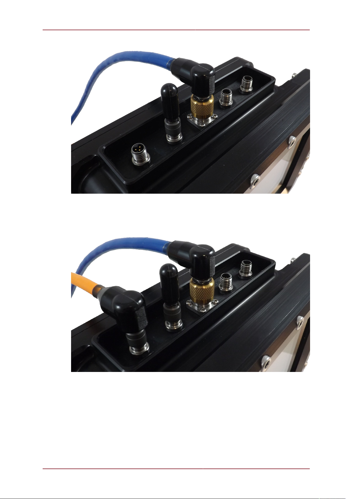
3.1. Plugging in the cables
At the top of the P-Sea are the connectors for
• Serial Comms
• Ethernet Comms
• USB
• Power

Getting Started P-Sea Underwater Console
0744-SOM-00002-1 11 © Tritech International Ltd.
The SERIAL port closest to the edge of the P-Sea corresponds to COM Port 1 within
the embedded PC and is preset for RS485 communications. The SERIAL port next to the
ETHERNET port is COM Port 2 and this is preset for RS232 communications.
The USB port can be used to connect external USB devices, via its USB Cable, to the P-
Sea, such as a mouse, keyboard or external HDD. A USB Hub can be used with this port
to allow more than one USB device to be connected at any one time. This is recommended
when attempting to transfer data from the P-Sea (see Section 5.4, “ Transferring Data ”) or
attempting to use some of the more advanced features of the Gemini software (see Chapter 6,
Advanced Operation).
The USB Port must be blanked off if the unit is being submerged. The USB Cable for the P-
Sea is not rated for use underwater and is intended for dry use only.
Using the Gemini sonar cable, plug into the ETHERNET port on the P-Sea and onto the main
port of the Gemini sonar.
Getting Started P-Sea Underwater Console
0744-SOM-00002-1 12 © Tritech International Ltd.
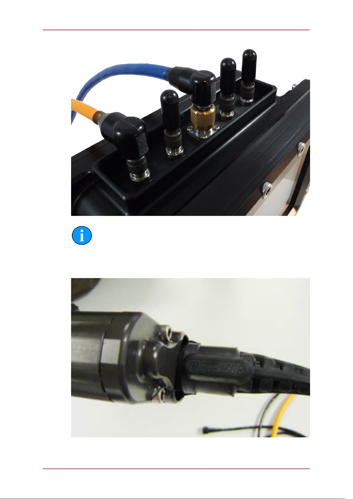
Connect the MetalSub Power Cable to the P-Sea Power port
As no serial devices are being connected, ensure that both Serial Ports have also been
blanked off prior to the unit being submerged.
Getting Started P-Sea Underwater Console
0744-SOM-00002-1 13 © Tritech International Ltd.
Note
All the connectors on the P-Sea should be hand tightened, with care taken to
observe the orientation of the connectors prior to fitting.
Remove the blanking caps from the MetalSub batteries, by turning ¼ turn anti-clockwise,
and store in a safe place. Once all the other ports are connected, or blanked off, attach both
batteries to the MetalSub Power Cable.
The P-Sea will now power up, with the display showing a NO SYNC message.
Getting Started P-Sea Underwater Console
0744-SOM-00002-1 14 © Tritech International Ltd.
3.2. First power on
Note
When powering on the P-Sea for the first time it is highly recommended that
it is done as a dry test with the USB Cable attached. This will enable you
to acknowledge any Windows® OS messages that may obscure the screen.
Typically this only needs to be done once.
When the P-Sea powers on it will show a NO SYNC message on screen. To activate the unit
fully, press and hold the POWER button for about 3 seconds.

Getting Started P-Sea Underwater Console
0744-SOM-00002-1 15 © Tritech International Ltd.
The P-Sea will now boot up the internal computer and, after a short delay, the Gemini software
will be automatically loaded.
Once fully loaded, the Gemini software will automatically detect the attached Gemini sonar
and enable it for use.

Getting Started P-Sea Underwater Console
0744-SOM-00002-1 16 © Tritech International Ltd.
If the Gemini sonar is not submerged in water, an “Out Of Water” warning will be displayed.
This will disappear from screen once the unit is submerged. Control of the Gemini sonar
and software is discussed, in depth, in Chapter 5, Basic Operation and Chapter 6, Advanced
Operation.

P-Sea Underwater Console
0744-SOM-00002-1 17 © Tritech International Ltd.
4. Installation
The following pin out diagrams details the connections on the P-Sea
4.1. Power Connector
Bulkhead View Pin Function Cable View
1 + V
2 0 VDC
3 N/C
1
2
3
1
2
3
4.2. Sonar Connector
Bulkhead View Pin Function Cable View
1 0 VDC
2 + V
3 SCREEN
4 Ethernet RX-
5 Ethernet RX+
6 Ethernet TX+
7 Ethernet TX-
4
1
2
53
6
7
4
12
5
3
67

Installation P-Sea Underwater Console
0744-SOM-00002-1 18 © Tritech International Ltd.
4.3. Serial Connectors
COM Port 1 - RS485
Bulkhead View Pin Function Cable View
1 RS485 A
2 RS485 B
3 + V
4 0 VDC
5 N/C
6 SCREEN
3
1
2
54
6
3
1
2
54
6
COM Port 2 - RS232
Bulkhead View Pin Function Cable View
1 RS232 Tx
2 RS232 Rx
3 + V
4 0 VDC
5 RS232 Ground
6 SCREEN
3
1
2
54
6
3
1
2
54
6

Installation P-Sea Underwater Console
0744-SOM-00002-1 19 © Tritech International Ltd.
4.4. USB Connector
Bulkhead View Pin Function Cable View
1 Data -VE
2 Data +VE
3 5V DC
4 0 VDC
1
2
43
1
2
43

P-Sea Underwater Console
0744-SOM-00002-1 20 © Tritech International Ltd.
5. Basic Operation
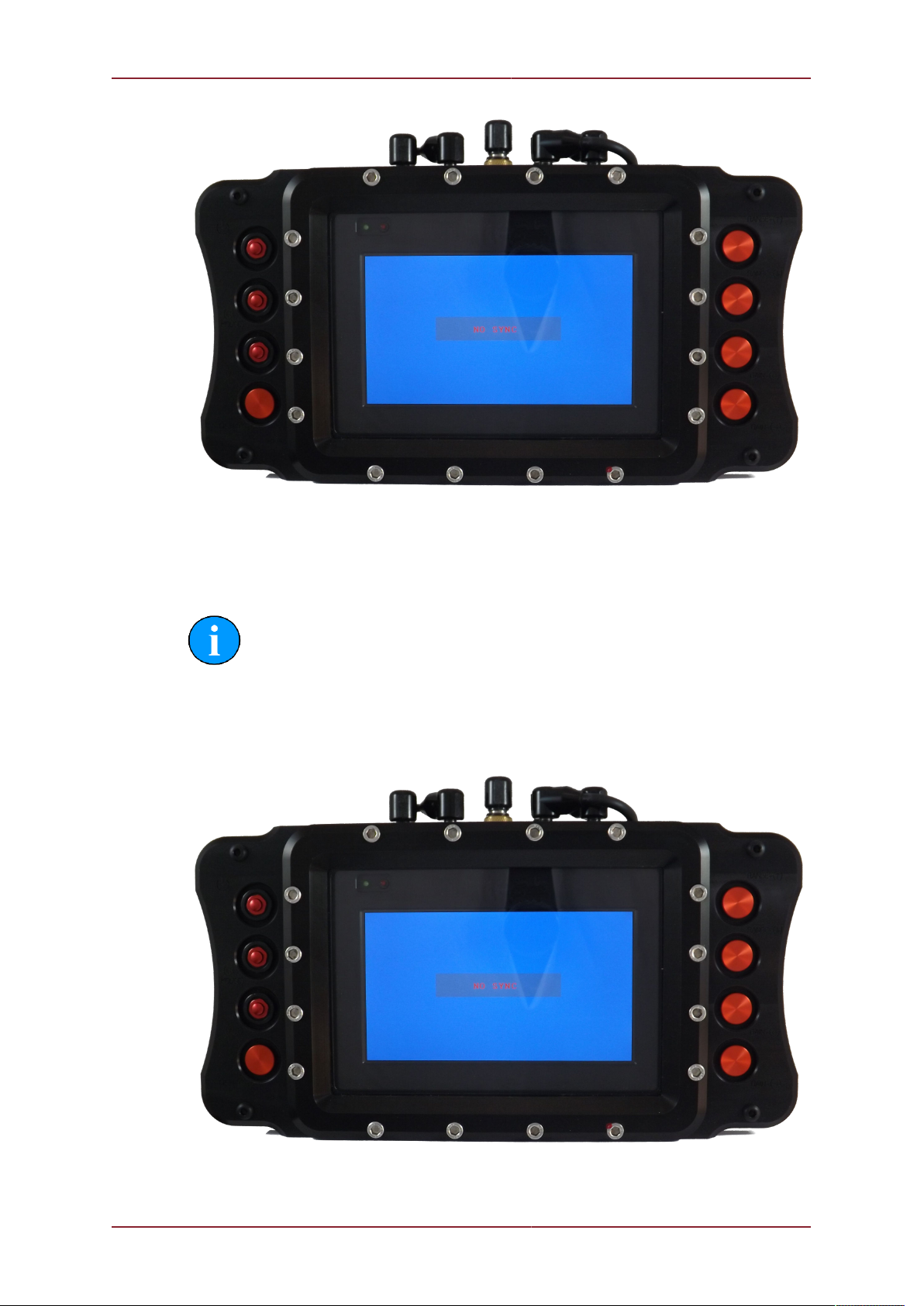
5.1. Activity Indicators
At the top left of the P-Sea window there are two LEDs which are used to indicate its power
status and any activity that's being carried out.
The GREEN LED is used to indicate if power has been enabled.
The RED LED is used to indicate activity on the internal storage drives. During normal
operation this will may blink at seemingly random intervals.
5.2. User Controls
The P-Sea has a set of optimised controls for use subsea, providing a simplified interface for
performing the most common actions for controlling an attached Gemini sonar.
On either side of the P-Sea there are a series of control buttons.
Table of contents
Popular Diving Instrument manuals by other brands


Northern Diver
Northern Diver EVOLUTION 8 manual

Outland Technology
Outland Technology 6200 user manual

Uwatec
Uwatec HYDROS PRO user guide

Dive Rite
Dive Rite NiTek Q4 quick start guide

Johnson Outdoors
Johnson Outdoors Scubapro Uwatec A 700 2nd Stage Maintenance Procedure

Shearwater
Shearwater Perdix 2 operating instructions


