BlueRadios nBlue BR-EVAL-LE4.0-X2A User manual

Page 1 of 2
BR-EVAL-LE4.0-X2A Quick Start Guide v3.1.0
Copyright © 2002-2012 BlueRadios, Inc.
7173 S. Havana Street, Suite 600 •Englewood, CO 80112 • (303)-957-1003 • sales@BlueRadios.com
www.BlueRadios.com
n
Blue BR-EVAL-LE4.0-X2A Quick Start Guide
1 Kit Contents
n
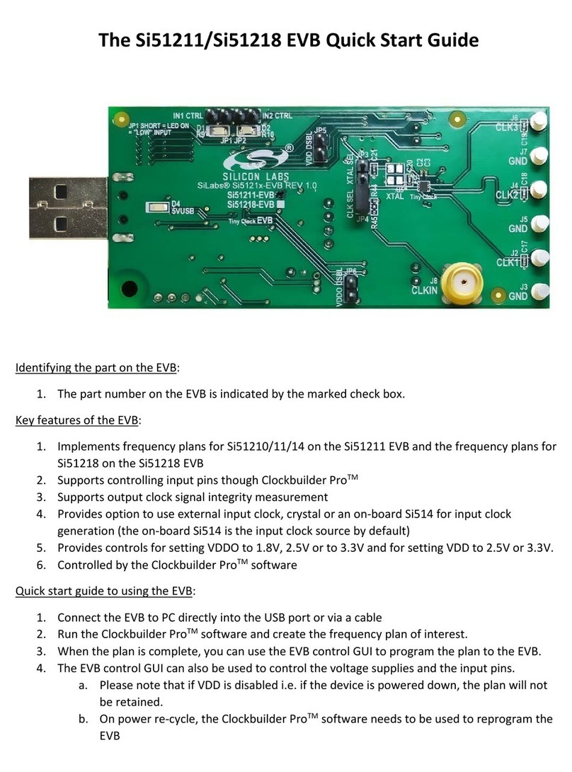
Blue USB Dongle (Dongle) w/
n
Blue BR-LE4.0-X2A Module (X = S for Single Mode, D for Dual Mode)
n
Blue Development Board (DevBoard) w/
n
Blue BR-LE-4.0-X2A Module and Micro-USB cable.
2 Important Notes
The modules operate at a supply voltage (VDD) of 2.0-3.6V, 3.0V is recommended.
The maximum voltage level on any pin should not exceed 3.6V. The I/O is NOT 5V tolerant.
<cr> = Carriage Return (ENTER key, 0x0D), <cr_lf> = Carriage Return + Linefeed (0x0D0A)
3 Drivers
The Dongle and the DevBoard both require virtual COM port drivers, which can be obtained from:
http://www.ftdichip.com/Drivers/VCP.htm. Windows will automatically locate and install these drivers.
4 Documentation and Firmware Updates
Module documentation and firmware updates can be downloaded from: http://www.blueradios.com/forum.
5 Quick Start Using Windows and HyperTerminal
5.1 Terminal Setup
1. Plug the Dongle into an available USB port on your PC and a red power
led will come on. Follow the prompts to install the device and be sure to
note the COM port that has been assigned to the Dongle. The assigned
COM port number can be found in Device Manager under Ports.
2. Open a new HyperTerminal session named “Master-Dongle”, with factory
default settings (do not echo characters or append any additional line
feeds). Connect to the COM port assigned to your Dongle at 115200, 8-
N-1, with hardware flow control.
3. On the DevBoard set the power switch to the USB position and then
connect the provided USB cable to the USB connector labeled “UART”.
Plug the cable into an available USB port on your PC and the red VBUS
led will come on. The PIO5 led will also start pulsing every 2 seconds,
indicating the module is discoverable. The DevBoard will install two COM
ports, the port with the higher number is the one you will be using.
4. Open another new HyperTerminal session named “Slave-DevBoard" with
factory default settings (do not echo characters or append line feeds).
Connect to the COM port assigned to your DevBoard at 115200, 8-N-1,
with hardware flow control.
5. To verify communication with each module, type “AT<cr>” in each terminal and the module will respond OK.
COMMAND: AT<cr> RESPONSE: <cr_lf>OK<cr_lf>
6. Read and record the Bluetooth Address from the DevBoard by typing “ATA?<cr>” in the DevBoard terminal.
COMMAND: ATA?<cr> RESPONSE: <cr_lf>OK<cr_lf><cr_lf>ECFE7EXXXXXX<cr_lf>
5.2 Making a Low Energy (LE) Connection
1. If you are using a Dual Mode module, make the DevBoard discoverable by typing “ATDSLE<cr>” in the
DevBoard terminal. (Single Mode modules are LE discoverable by default.)
COMMAND: ATDSLE<cr> RESPONSE: <cr_lf>OK<cr_lf>
2. Next, try to discover the DevBoard from the Dongle by typing “ATDILE<cr>” in the Master-Dongle terminal.
COMMAND: ATDILE<cr> RESPONSE: <cr_lf>OK<cr_lf>
The Dongle will respond with multiple discovery events depending on how many LE devices are in the area.
By default the module does an active scan discovery, so up to 2 events may print for each discovered device.

Page 2 of 2
BR-EVAL-LE4.0-X2A Quick Start Guide v3.1.0
Copyright © 2002-2012 BlueRadios, Inc.
7173 S. Havana Street, Suite 600 •Englewood, CO 80112 • (303)-957-1003 • sales@BlueRadios.com
www.BlueRadios.com
EVENT: <cr_lf>DISCOVERY,2,ECFE7EXXXXXX,0,-045,4,AD_DATA<cr_lf>
EVENT: <cr_lf>DISCOVERY,6,ECFE7EXXXXXX,0,-045,2,SCAN_DATA<cr_lf>
After 10 seconds, or the maximum number of devices have been found, the module will send a DONE event:
EVENT: <cr_lf>DONE,1,1<cr_lf>
The discovery events return the advertising and scan response data of nearby advertising LE modules. The
12 characters in the third field of the response are the remote module’s Bluetooth Address.
3. Once you have discovered your DevBoard you are ready to connect to it. In the Master-Dongle terminal, type
“ATDMLE,XXXXXXXXXXXX<cr>”, filling in the X’s with the DevBoard’s address.
COMMAND: ATDMLE,ECFE7EXXXXXX<cr> RESPONSE: <cr_lf>OK<cr_lf>
4. Once connected, both modules will send a CONNECT event, showing the address of the remote device. A
BRSP event will also be sent, signaling that the modules are in BRSP data mode. At this point data can be
sent by typing into either terminal.
EVENT: <cr_lf>CONNECT,0,1,0,ECFE7EXXXXXX<cr_lf>
EVENT: <cr_lf>BRSP,0,1<cr_lf>
5. To disconnect, first type “+++<cr>” into either terminal. This escape sequence will take the module out of
BRSP data mode and put it into command mode.
COMMAND: +++<cr> RESPONSE: <cr_lf>OK<cr_lf>
Next, type “ATDH,0<cr>” and the connection will be terminated.
COMMAND: ATDH,0<cr> RESPONSE: <cr_lf>OK<cr_lf>
EVENT: <cr_lf>DISCONNECT,0,0<cr_lf>
A disconnect event will also print from the remote module as well.
EVENT: <cr_lf>DISCONNECT,0,1<cr_lf>
5.3 Making a Classic Bluetooth (CB) Connection – Dual Mode Only
1. Dual Mode modules are CB discoverable by default, so the DevBoard can be discovered by typing “ATDI<cr>”
in the Master-Dongle terminal.
COMMAND: ATDI<cr> RESPONSE: <cr_lf>OK<cr_lf>
The Dongle will respond with multiple discovery events depending on how many CB devices are in the area.
Only one event will be sent per device, as opposed to up to 2 for LE.
EVENT: <cr_lf>DISCOVERY,1,ECFE7EXXXXXX,000000,-045,3,EIR_DATA<cr_lf>
After 10 seconds, or the maximum number of devices have been found, the module will send a DONE event:
EVENT: <cr_lf>DONE,0,1<cr_lf>
2. To make a CB connection, type “ATDM,XXXXXXXXXXXX<cr>” in the Master-Dongle terminal, filling in the X’s
with the DevBoard’s address.
COMMAND: ATDM,ECFE7EXXXXXX<cr> RESPONSE: <cr_lf>OK<cr_lf>
3. Once connected, both modules will send a PAIRED event, followed by a CONNECT event, showing the
address of the remote device. An SPP event will also be sent, signaling that the modules are in SPP data
mode. At this point data can be sent by typing into either terminal.
EVENT: <cr_lf>PAIRED,ECFE7EXXXXXX,1<cr_lf>
EVENT: <cr_lf>CONNECT,0,0,0,ECFE7EXXXXXX<cr_lf>
EVENT: <cr_lf>SPP,0,1<cr_lf>
To disconnect, first type “+++<cr>” to take the module out of SPP data mode and put it into command mode.
Then type “ATDH,0<cr>” and the connection will be terminated.
COMMAND: +++<cr> RESPONSE: <cr_lf>OK<cr_lf>
COMMAND: ATDH,0<cr> RESPONSE: <cr_lf>OK<cr_lf>
EVENT: <cr_lf>DISCONNECT,0,0<cr_lf>
A disconnect event will also print from the remote module as well.
EVENT: <cr_lf>DISCONNECT,0,1<cr_lf>

Contains Transmitter Module FCC ID: XDULE40-D2A, IC: 8456A-LE4-D2
Federal Communications Commission (FCC) Statement
You are cautioned that changes or modifications not expressly approved by the part responsible for
compliance could void the user’s authority to operate the equipment.
This equipment has been tested and found to comply with the limits for a Class B digital device, pursuant
to part 15 of the FCC rules. These limits are designed to provide reasonable protection against harmful
interference in a residential installation. This equipment generates, uses and can radiate radio frequency
energy and, if not installed and used in accordance with the instructions, may cause harmful interference to
radio communications. However, there is no guarantee that interference will not occur in a particular
installation. If this equipment does cause harmful interference to radio or television reception, which can be
determined by turning the equipment off and on, the user is encouraged to try to correct the interference by
one or more of the following measures:
-Reorient or relocate the receiving antenna.
-Increase the separation between the equipment and receiver.
-Connect the equipment into an outlet on a circuit different from that to which the receiver is connected.
-Consult the dealer or an experienced radio/TV technician for help.
This device complies with Part 15 of the FCC Rules. Operation is subject to the following two conditions:
1) this device may not cause harmful interference, and
2) this device must accept any interference received, including interference that may cause undesired
operation of the device.
FCC RF Radiation Exposure Statement:
This equipment complies with FCC radiation exposure limits set forth for an uncontrolled environment.
End users must follow the specific operating instructions for satisfying RF exposure compliance. This
transmitter must not be co-located or operating in conjunction with any other antenna or transmitter.
Industry Canada (IC) Statement
This device complies with Industry Canada licence-exempt RSS standard(s). Operation is subject to the
following two conditions: (1) this device may not cause interference, and (2) this device must accept any
interference, including interference that may cause undesired operation of the device.
Canada, avis d’Industry Canada (IC)
Le présent appareil est conforme aux CNR d'Industrie Canada applicables aux appareils radio exempts
delicence. L'exploitation est autorisée aux deux conditions suivantes:
(1) l'appareil ne doit pas produire de brouillage, et
(2) l'utilisateur de l'appareil doit accepter tout brouillage radioélectrique subi, même si le brouillage est
susceptible d'en compromettre le fonctionnement.

FCC RF Radiation Exposure Statement:
This equipment complies with FCC radiation exposure limits set forth for an uncontrolled environment.
This equipment should be installed and operated with minimum distance 20cm between the radiator & your
body. This transmitter must not be co-located or operating in conjunction with any other antenna or
transmitter.
Table of contents
Popular Computer Hardware manuals by other brands

AXIOMTEK
AXIOMTEK rBOX310-FL Quick installation guide
SIIG
SIIG I/O Expander 2S Quick installation guide
NXP Semiconductors
NXP Semiconductors MIMXRT1170HDUG Hardware development guide
StarTech.com
StarTech.com PEX4S953 quick start guide
Peavey
Peavey MediaMatrix MM-760nt Specifications

DeLOCK
DeLOCK 90097 user manual
ST
ST TDA911 Series Application note
Cypress Semiconductor
Cypress Semiconductor CY7C1041DV33 Specification sheet
Massive Audio
Massive Audio CORE-1 user manual
MEI
MEI easitrax ADV 5 Series Installation booklet
Intel
Intel E5420 - CPU XEON QUAD CORE 2.50GHZ FSB1333MHZ 12M LGA771 HALOGEN FREE... specification

DEVA
DEVA Maximizer Quick user guide


