Bluesky SUB 15 UNIVERSAL User manual

Blue Sky International
70 Sea Lane
Farmingdale, NY 11735
www.abluesky.com
Owner’s Manual
Version 1.9R | January 18, 2005
Blue Sky | SUB 15
Universal
1000-Watt subwoofer with adaptive x-over

Contents
Important Safety Instructions _ __ __ __ __ __ __ __ __ __ _ Page 3
1 SUB 15 Universal Introduction _ __ __ __ __ __ _ Page 4
2 Important notes about the SUB 15 Universal and this
Owner’s manual _ __ __ __ __ __ __ __ __ __ __ _ Page 4
3 SUB 15 Universal - What is included?_ __ __ __ _ Page 4
4 Quick Setup / with lter setting instructions _ _ Page 5
5 System Signal Connections _ __ __ __ __ __ __ _ Page 6
6 Expanded Calibration Guide _ __ __ __ __ __ _ Page 7
7 A Tour of the Amplier and I/O _ __ __ __ __ _ Page 8
8 Subwoofer Placement Guide _ __ __ __ __ __ _Page 10
9 Technical Information _ __ __ __ __ __ __ __ __ _ Page 11
10 SUB 15 Universal Cabinet Dimensions _ __ __ _Page 12
11 Factory Service Instructions _ __ __ __ __ __ __ _Page 13
12 General Contact Details _ __ __ __ __ __ __ __ _Page 13
Contents

1 READ INSTRUCTIONS - Read all safety and operating instructions
before operating this product.
2. RETAIN INSTRUCTIONS - Retain these safety and operating
instructions for future reference.
3. HEED WARNINGS - Follow all warnings on this product and in the
operating instructions.
4. FOLLOW INSTRUCTIONS - Follow all operating and use
instructions.
5. ATTACHMENTS - Do not use attachments not recommended by the
product manufacturer as they may cause hazards.
6. WATER AND MOISTURE - Do not use this product near water - for
example, near a bathtub, washbowl, kitchen sink, or laundry tub; in
a wet basement; or near a swimming pool; and the like.
7. ACCESSORIES - Do not place this product on an unstable cart,
stand, tripod, bracket, or table. The product may fall, causing serious
injury to a child or adult, and serious damage to the product. Use
only with accessories recommended by the manufacturer, or sold
with the product. Any mounting of the product should follow the
manufacturer’s instructions and should use a mounting accessory
recommended by the manufacturer.
8. POWER SOURCE - This product should be operated only from the
type of power source indicated on the marking label on the back of
the product. It is IMPORTANT to conrm that the voltage selector
switch on the back of the subwoofer is set to the proper voltage
setting. If you are unsure of the type of power that is supplied to
your home, consult your product dealer or local power company.
9. LIGHTNING- For added protection for this product during a
lightning storm, or when it is left unattended and unused for long
periods of time, unplug it from the wall outlet. This will prevent
damage to the product due to lightning and power-line surges.
10. OVERLOADING - Do not overload wall outlets or extension cords
as this can result in a risk of re or electric shock.
11. LIQUID ENTRY - Never spill any liquid of any kind on the product.
12. SERVICING - Do not attempt to service this product yourself.
Opening or removing covers, including any over bottom or side
speaker drivers, may expose you to dangerous voltage or other
hazards. Refer all service to qualied service personnel.
13. DAMAGE REQUIRING SERVICE - Unplug this product from the
wall outlet and refer servicing to qualied personnel under the
following conditions:
a. When the power-supply cord or plug is damaged.
b. If liquid has been spilled, or objects have fallen into this
product.
c. If the product does not operate normally by following the
operating instructions. Adjust only controls that are covered
by the operating instructions as an improper adjustment of
other controls may result in damage and will often require
extensive work by a qualied technician to restore the
product to its normal operation.
d. If the product has been dropped or damaged in any way.
e. When the product exhibits a distinct change in performance
- this indicates a need for service.
14. REPLACEMENT PARTS - When replacement parts are required be
sure the service technician has used replacement parts specied
by the manufacturer or have the same characteristics as the original
part. Unauthorized substitutions may result in risk of re, electric
shock, or other hazard.
15. SAFETY CHECK - Upon completion of any service or repairs to this
product, ask the service technician to perform safety checks to
determine that the product is in proper operating condition.
16. HEAT - This product should be situated away from heat sources
such as radiators, heat registers, stoves, or other products that
produce heat.
Safety Instructions
Page 3

Page 4
1. SUB 15 Universal
Introduction
Blue Sky is a philosophy. We design each product to represent the highest
ratio possible of performance to cost, providing the highest value added to
our customers.
We will continually seek out opportunities to utilize the talent of the Blue Sky
team to realize this philosophy. Our customer’s value requirements will always
be our prime focus, and only those products that achieve our performance
value ratio will earn the right to carry the Blue Sky logo.
To that end we are proud to introduce the Blue Sky SUB 15 Universal 1000-Watt
subwoofer. The SUB 15 Universal is a sealed box subwoofer, designed around
a 15” forward-ring driver with a massive cast aluminum frame, dual 2.5” voice
coils - which has almost 2.36” of excursion (peak to peak) and features an
enormous 20+ Lbs. motor structure - total driver weight 36 Lbs. (see gure 1
for a detailed driver cutaway drawing). One of the SUB 15 Universal’s unique
features is a switchable low frequency response characteristic, of either
30Hz to 200Hz +/-3dB or, in “extended LF mode”, 20Hz to 200Hz +/-3dB
(anechoic). The extended mode is ideal for large rooms that don’t exhibit
the room gain phenomenon of smaller sealed spaces. In addition, the SUB
15 Universal also has built-in 2.1 bass management electronics with both a
4th order 80Hz Linkwitz-Riley low-pass lter and a 2nd order 80Hz high-pass
lter that is compatible with the SAT 12’s bass-managed input and is also
compatible with the SAT 6.5 and SAT 5.
The SUB 15 Universal is also the second subwoofer from Blue Sky which
allows you to add true low frequency extension to your existing neareld and
mid-eld monitors. To accomplish this, the SUB 15 Universal includes dual
independently tunable, state variable, high pass and low pass lters (50hz to
160Hz) with 4th order slopes.
We hope that this subwoofer brings you years of accurate and problem
free operation. We ask that you take the time to read this manual, register
the product and visit our website for any updated information regarding
this product. If you have any questions please don’t hesitate to contact us.
www.abluesky.com
Thank you for choosing Blue Sky!
2. Important notes about
the SUB 15 Universal
and this Owner’s
Manual
Voltage Selector Switch:
Prior to powering this unit, please conrm that the voltage selector switch,
located on the back of the subwoofer, has been set to the correct voltage
setting and that the proper fuse is installed. If you are unsure of the type of
power that is supplied to your home / studio, consult your product dealer or
local power company. Additionally, the SUB 15 Universal draws a maximum
of 1600 Watts and this needs be considered when sellecting a proper power
source.
The Owner’s Manual:
This manual primarily addresses the general features of the SUB 15 Universal,
along with SUB 15 Universal applications relating to setup and operation with
non Blue Sky neareld monitors. For setup information relating to the use of
this product with Blue Sky’s SAT 12, SAT 6.5 & SAT 5, please read the manual
that is included with the those specic products.
IMPORTANT, PLEASE NOTE: If you are planning to use the SUB 15 Universal
with Blue Sky’s SAT 12, SAT 6.5 or SAT 5, please set the selector switch on the
back of the SUB 15 Universal to the “BLUE SKY” setting. If you are you using the
SUB 15 Universal with the SAT 5, you will also need to set the 80Hz High Pass
Filter on the SAT 5 so that it is “OUT” of circuit.
3. SUB 15 Universal, what
is included?
The SUB 15 Universal includes the items listed below. Please carefully unpack
each item and inspect the components for damage. If any part of the system
has been damaged, please contact the dealer that supplied the product or
Blue Sky directly.
SUB 15 Universal Inventory:
1 SUB 15 Universal
1 Power Cable
1 Owner’s Manual
1 Warranty Card
Voltage
Selector Switch
Crossover
Selector Switch
Figure 1

Page 5
4. Quick Setup
1. If you haven’t already done so, carefully remove all items from the
packaging and conrm that everything that is listed on page 4 is
included. [SUB 15 Universal - What is included?].
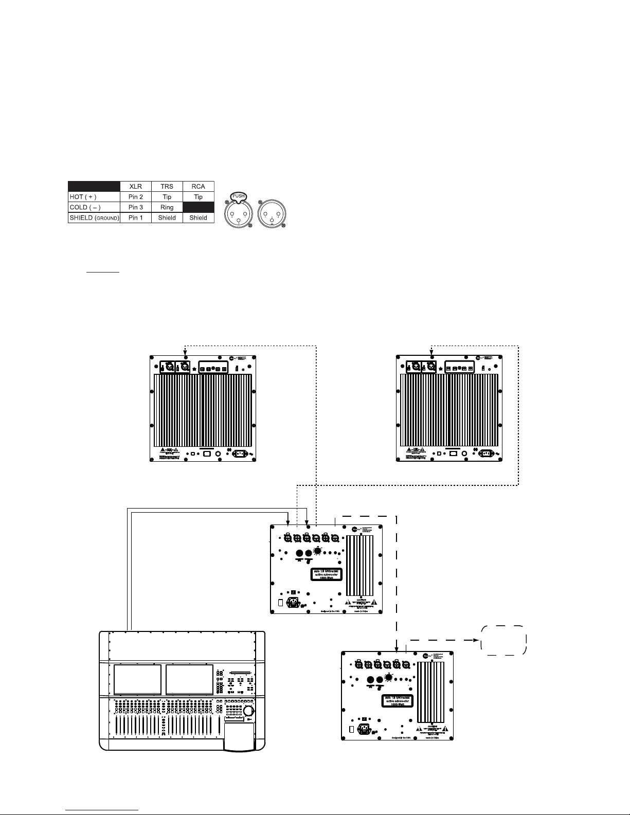
2. The SUB 15 Universal is compatible with XLR input / output
connections. For more information on connecting your system,
please see page 6 [System Signal Connection].
4. The rst step in the installation process is to position the subwoofer.
Although you have great exibility with regard to where the active
subwoofer can be placed, a good starting point is centered
between the left and right satellite speakers. This could be under
a console / desk, behind the console / desk, etc. For an expanded
subwoofer placement guide, please see page 9 [Subwoofer
Placement Guide].
5. Once the subwoofer is in position, connect the two input cables
from the left and right analog outputs from the mixing console,
digital workstation or other source, to the left and right inputs on
the subwoofer. For more information on connecting your system,
please see page 6 [System Signal Connection].
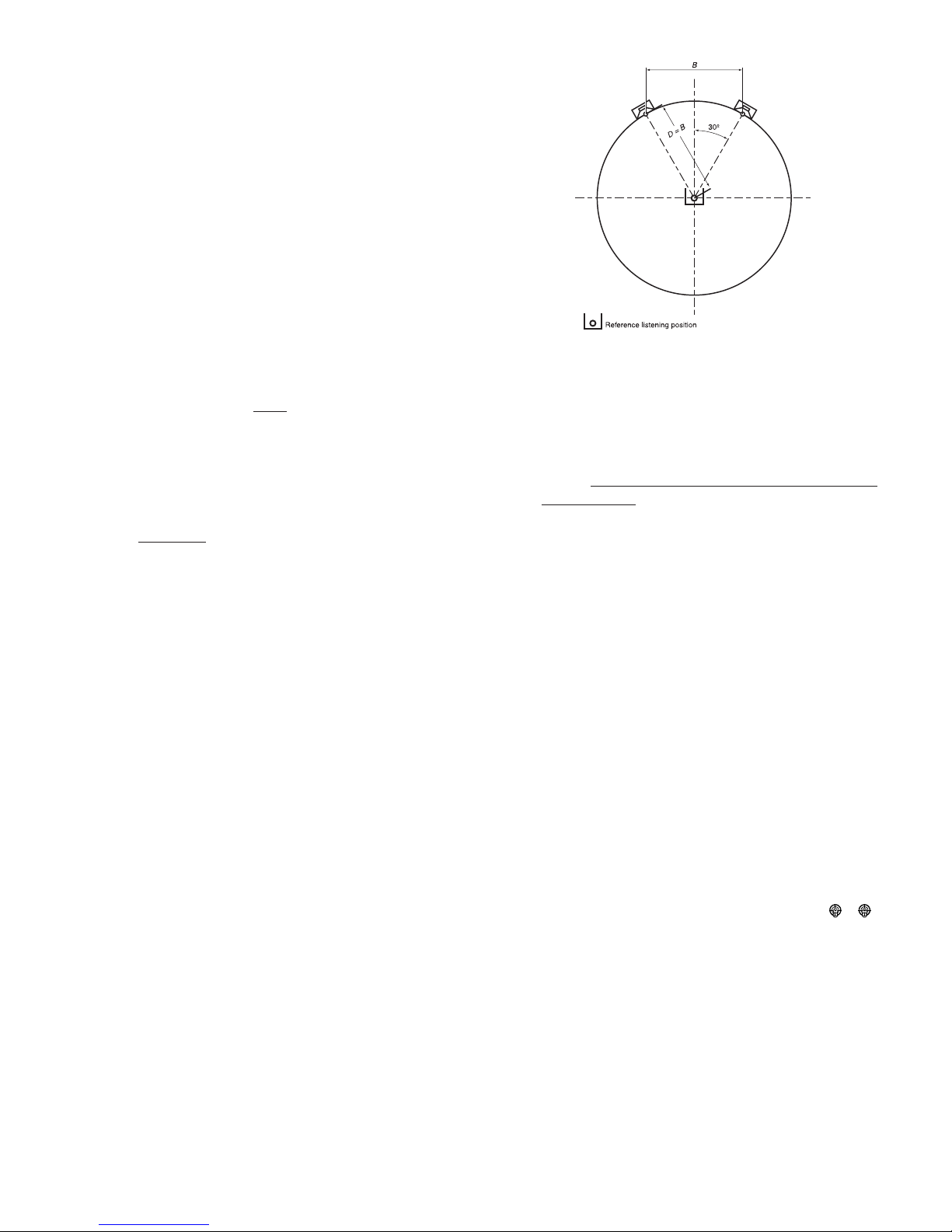
6. Our recommended position for the neareld monitors is based
on an ITU standard and sets the speakers at 60 degrees from the
listener, forming an equilateral triangle (a triangle with equal sides)
- See Figure 2. Fortunately, this setup eliminates most of the math
and is easily simplied to the following guidelines: If you want to
sit 1 meter (39.37 inches) from the monitors, place the speakers
1 meter apart. If you want to sit 6 ft. from the monitors, place the
speakers 6 ft. apart. Etc. Ideally your monitors should be at seated
ear height. If this is not possible, tilting the cabinet at the listening
area can improve high-frequency coverage.
7. Once all the monitors are properly placed, connect your left
neareld monitors to the left output on the back of the sub, via
XLR cable. Now do the same for the right channel, connecting the
right neareld to the right output. Lastly, please plug in the power
cord to the IEC connector on the subwoofer. Prior to proceeding
conrm that the system is wired correctly, as shown on page 6
[System Signal Connection].
8. At this point the monitoring system is correctly congured, and
ready for the nal step in the installation. Prior to plugging the
system into the wall outlet, and powering up the system, do a nal
quick check of all connections and level settings.
9. If everything is correct, plug the power cord into the wall outlet.
Do not turn on the power switches, yet! Some mixers and
out-board equipment such as D-to-A converters and equalizers
generate loud rail-to-rail pops when they initially turn-on.
Depending on the level and the gain setting of the monitoring
system, these pops could damage your monitors. To avoid this,
always turn on equipment in the following sequence: All sources
and mixer rst, then the SUB 15 Universal and then rest of your
monitoring system.
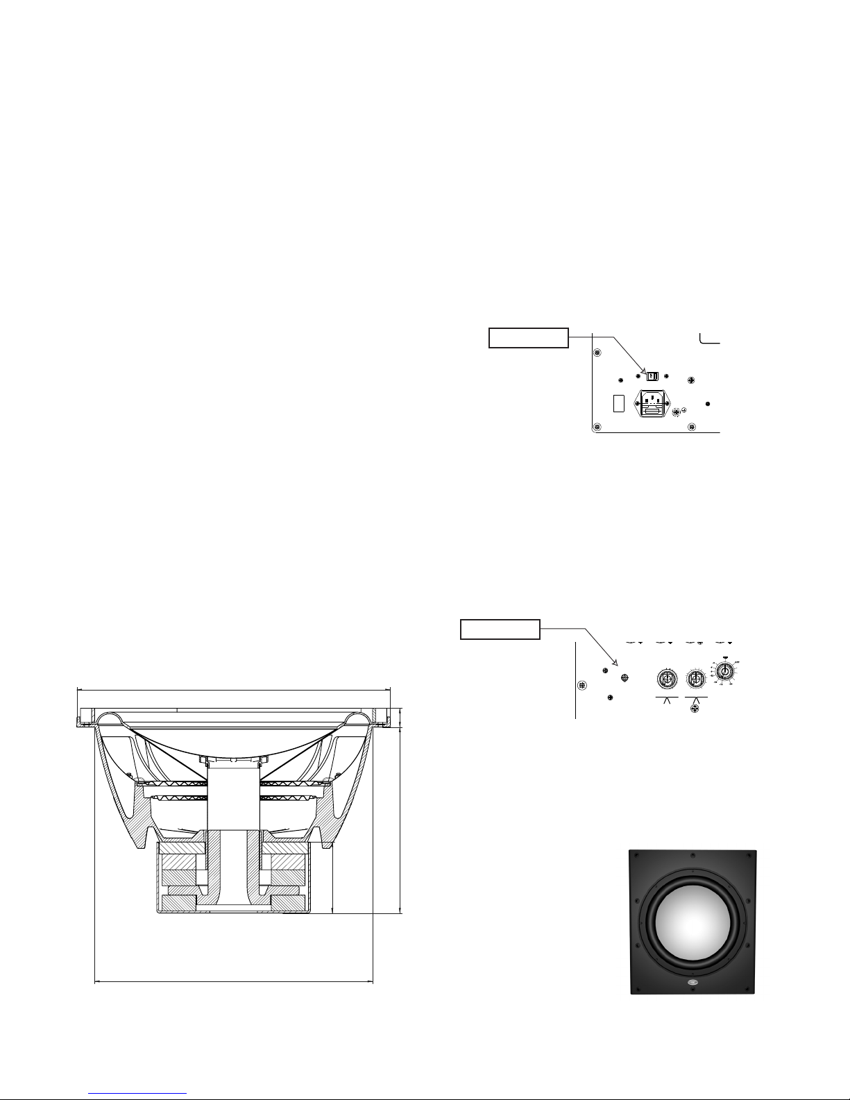
10. It is now time to set the Variable Cutoff Frequency on the back of
the SUB 15 Universal to best match your monitoring system (if you
are using the SUB 15 Universal with Blue Sky monitors, set the Filter
Selector Switch to “BLUE SKY” and skip to item 11). To determine
the proper lter setting on the SUB 15 Universal, you rst need to
know the cutoff frequency of your monitors. This can typically be
found in the manual, under specications and may look like this:
40Hz to 20kHz +/-3dB. The low frequency cutoff off for the
monitor in this example would be around 40Hz. We recommend
you set the SUB 15 Universal one octave above this cutoff
frequency. To go up one octave, multiply the LF cutoff frequency
times two. In our example this would be 80Hz, because 2 x 40Hz
= 80Hz. Make sure to set both the left and right channel to
the same setting.
11. At this point the Blue Sky monitoring system is fully operational, and
ready for use. Begin by playing familiar pieces of music, which can
assist you in the ne-tuning rst the level and then the placement
of the subwoofer. It is important to remember that the positioning
of the subwoofer in the room will impact the subwoofer level.
You may nd it necessary to increase or decrease the level of the
subwoofer to best match your monitors. Again use a familiar piece
of music which includes plenty of LF material to help you set the
proper level.
12. If a more exacting setup is required, using test signals and a SPL
meter, please see Page 9 [Expanded Calibration Guide].
13. Just remember - Use your ears, they are the best audio tool you
have and you will be amazed how accurate the setup can be if you
use familiar audio material during the setup of the system.
14. Congratulations! You have now completed the “quick setup” of the
SUB 15 Universal. If you have any questions, please do not hesitate
to contact us directly with your questions. (516) 249-1399 (9:00am
to 5:30pm EST) or visit our web forum www.abluesky.com/forum
A note about the LF EXTENSION and PHASE switches:
One of the SUB 15 Universal’s unique features is a switchable low
frequency response characteristic, of either 30Hz to 200Hz +/-
3dB or, in “extended LF mode”, 20Hz to 200Hz +/-3dB (anechoic),
marked 30Hz and 20Hz respectively. The extended mode is ideal
for large rooms that don’t exhibit the room gain phenomenon of
smaller sealed spaces. The only way to be absolutely sure of
which setting is appropriate for your studio is to use an acoustic analyzer.
Using the 20Hz in a sealed space, such as a small to medium size studio, can
result in a rising LF response characteristic below 30Hz.
The PHASE setting on the SUB 15 Universal should typically be set to 0,
especially when the SUB 15 Universal is used with Blue Sky SATs. However,
there may be times, depending on the speakers used with the SUB 15 Universal
or because of certain acoustic conditions, that the phase setting needs to be
set to 180, so as to get proper summation between SAT and SUB. The only way
to be absolutely sure which setting is appropriate for your studio is to use an
acoustic analyzer.
Figure 2

Page 6
5. System Signal
Connections
CABLE WIRING SPECIFICATIONS
Most users of the SUB 15 Universal will be using ready made
cables, however if you need to wire your own cables, follow the
wiring specications below.
XLR INPUTS (ELECTRONICALLY BALANCED)
Figure 2: The SUB 15 Universal’s XLR inputs can handle up to
+24dBu of signal level at the input and are compatible with most,
if not all professional gear. Additional adaptor cables can be
purchased from most professional audio dealers, so that the SUB
15 Universal can be used with other output types (TRS, RCA etc.)
Figure 3
�
FLATPOSITION IS ALL SWITCHES DOWN
�
FLATPOSITION IS ALL SWITCHES DOWN

Page 7
6. Expanded Calibration
Guide
Instructions for electroacoustic calibration of a 2.1 audio system using
a SPL meter and Blue Sky’s test les.
Before starting this procedure you will need to download BlueSkyTestFiles.zip
(an 18 MB zip le) by going to www.abluesky.com/calibration. To download
the test le, “Right Click” and select “Save Target As”. The le will begin
downloading once a location has been selected.
Once downloaded, either burn the test les to a CD or import them into your
DAW and follow the instructions below.
ADDITIONAL REQUIRED ITEMS
1. 2.1 Monitoring System
2. SPL Meter - such as the SPL meter sold by RadioShack
in the U.S.
BlueSkyTestFiles.zip Includes 4 les:
• 1000Hz SINEWAVE -20dBFS.wav – a 1kHz le recorded at -
20dBFS for electrical calibration
• 40-80Hz PINK NOISE -20dBFS.wav – a 40Hz to 80Hz bandwidth
limited pink-noise le recorded at -20dBFS
• 500-2.5kHz PINK NOISE -20dBFS.wav – a 500Hz to 2.5Hz
bandwidth limited pink-noise le recorded at 20dBFS
• Pink Noise full bw -20dBFS.wav – a full-bandwidth pink-noise le
recorded at - 20dBFS
These test les are all mono les. Please make sure you hard assign
them to the left and then the right, not both channels at the same time.
If you are using a CD player use only one channel of the CD player.
THEORY
The purpose of calibration is to adjust the overall electroacoustics system gain
so that 0dBVU of electrical signal level equals a certain acoustic level at the
listening position. Since most recording media is now digital, the reference
electrical signal level is usually –20dBFS with 20dB of headroom. The reference
SPL level however can vary based on the delivery media and speaker type.
Please note that the bandwidth limited signals that have been provided, limit
many of the room interaction affects often associated with measuring SPL and
broadband pink noise.
All test signals are recorded at –20dBFS including the 1 kHz sine wave tone.
The sine wave tone is used to set the electrical output level throughout the
signal path, right up to the point you get to the speakers, while the various pink
noise signals are used for acoustic measurements and calibration.
The following procedure assumes you are calibrating the system to 85dBC
SPL.
Step 1 TURN OFF THE MONITORING SYSTEM (until step 4)
Step 2 Remove all eq and dynamics from the signal path and set all
controls to zero / unity gain. Play the 1kHz Sine Wave, hard assign
it to the left channel only, and adjust the output fader so the output
meter reads -20dBFS. If you are using an analog console, set the
output level to 0 VU. Then hard pan the signal to the right channel
output and repeat for the right channel. Once calibrated do not
move the output faders.
Step 3 Mute everything and make sure the 1kHz tone is OFF .
Step 4 Now that the system has been electrically calibrated
turn ON your 2.1 System (SUB 15 Universal + monitors).
Step 5 Assign the 500-2.5kHz pink noise signal to the left channel only.
Make sure there is nothing coming from the right channel (or any
other channels). Because this signal is bandwidth limited, you
don’t have to worry about turning the sub off. There are two
methods of setting the levels.
A. If you have a master monitor level control, you can set the sat
gain control at reference and then adjust the monitor gain control
for 85 dBC. Then mark the monitor level as your reference position.
B. The other method is to set master monitor level to the position
you want as a reference level and then use the volume controls
to set 85 dBC. If you use this method you should mark the knob
position with a grease pencil so you can always go back to
reference level if the knob gets moved.
For either method:
SPL should be measured at the mix position, with the SPL meter
at arms length, with the microphone at seated ear height, angled
at approximately 45 degrees, and pointed at the center point
between the left and right speakers.
Once the left channel is set to 85dBC, repeat this step for the right
channel
Step 6 Feed 40-80Hz pink noise signal to the left channel only. Adjust the
subwoofer level control until the subwoofer reads 85dBC (slow)
at the mix position. The meter will bounce around a little, so you
will need to do a mental average (I tend to lter out the peaks in
my mind, so I don’t set the sub too hot). The right channel should
measure about the same and no additional adjustments need to be
made.
Step 7 You can play the full-bandwidth pink noise, assigning it to the left
and then the right channel (not at the same time). You should
measure about 85dBc. It may be a little higher, because below
30Hz the room may have a little extra gain. No adjustments should
be made with Full Bandwidth pink noise, unless you have an RTA
(real time analyzer).
Step 8 You are nished and the calibration process has been completed
– enjoy!
A note about the LF EXTENSION and PHASE switches:
One of the SUB 15 Universal’s unique features is a switchable
low frequency response characteristic, of either 30Hz to 200Hz
+/-3dB or, in “extended LF mode”, 20Hz to 200Hz +/-3dB
(anechoic), marked 30Hz and 20Hz respectively. The extended
mode is ideal for large rooms that don’t exhibit the room gain
phenomenon of smaller sealed spaces. The only way to be absolutely sure
of which setting is appropriate for your studio is to use an acoustic analyzer.
Using the 20Hz in a sealed space, such as a small to medium size studio, can
result in a rising LF response characteristic below 30Hz.
The PHASE setting on the SUB 15 Universal should typically be set to 0,
especially when the SUB 15 Universal is used with Blue Sky SATs. However,
there may be times, depending on the speakers used with the SUB 15 Universal
or because of certain acoustic conditions, that the phase setting needs to be
set to 180, so as to get proper summation between SAT and SUB. The only way
to be absolutely sure which setting is appropriate for your studio is to use an
acoustic analyzer.

Page 8
7. A Tour of the SUB 15
Universal Amplifier and I/O

Page 9
7. A Tour of the SUB 15
Universal Amplifier
and I/O
1. LEFT / RIGHT XLR IN - These XLR inputs should be connected to
the left / right output of your console or digital workstation. The
inputs are electronically balanced. Do not connect more than
one source to these inputs. Refer to page 6 for more information
[System Signal Connection].
2. LEFT / RIGHT XLR OUT- These XLR outputs should be connected
to the inputs of your left / right neareld or mid-eld monitors. The
outputs are electronically balanced. [System Signal Connection].
3. UNIVERSAL / BLUE SKY FILTER SWITCH - This switch is used to
either activate the variable state lters, or activate the xed 80Hz
low pass and high pass lters that are required for use with Blue
Sky monitors. If you are using the SUB 15 Universal with the SAT 5,
you will also need to set the 80Hz High Pass Filter on the SAT 5 so
that it is “OUT” of circuit.
4. VARIABLE CUTOFF FREQUENCY CONTROL KNOBS - These
controls are for adjusting the dual 24dB per octave low and high-
pass lters. The cutoff frequency can be adjusted from 50Hz to
160Hz. It is recommended that the SUB 15 Universal’s lters be
set one octave above the natural roll off of the neareld monitors
that are being used with the SUB 15 Universal. To activate these
variable lters, the UNIVERSAL / BLUE SKY SWITCH - must be in the
up position (VARIABLE). For more information see item 10 on page
5 [Quick Setup].
5. VOLTAGE SELECTOR SWITCH- This switch can be set to either 115
Volts or 230 volts. Prior to powering this unit, please conrm that
the Voltage selector switch, located on the back of the subwoofer,
has been set to the correct voltage setting. If you are unsure of
the type of power that is supplied to your home / studio, consult
your product dealer or local power company. If your changing
the Voltage, please also conrm the proper fuse is installed [see
number 6].
6. POWER SWITCH - Controls the power to the amplier and all
internal electronics.
7. FUSE HOLDER / IEC RECEPTACLE - Replace with same rating and
type for your local voltage rating. For 115V applications use a 15
Amp T 250V and for 230 Volt applications use a 8 Amp T 250V
fuse. Check voltage selector switch before connecting power (T
stands for time delay or SloBlo). Connect to 115 Volt AC / 60Hz
power source, rated for 1600 WATTS or 230 Volt / 50Hz rated
for 1600 WATTS. Only use the supplied power cord or an IEC
approved power cord with a safety ground pin.
8. AMPLIFIER HEATSINK- The heatsink provides essential cooling to
the amplier inside the SUB 15 Universal. Please ensure that proper
air circulation is available for proper cooling.
9. SUB GAIN - This knob controls the input sensitivity of the
subwoofer amplier only. When set to the reference position a
100mV signal at the input equals 90dB output at a meter.
10. LF Extension - One of the SUB 15 Universal’s unique features is a
switchable low frequency response characteristic, of either 30Hz
to 200Hz +/-3dB or, in “extended LF mode”, 20Hz to 200Hz +/-3dB
(anechoic), marked 30Hz and 20Hz respectively. The extended
mode is ideal for large rooms that don’t exhibit the room gain
phenomenon of smaller sealed spaces. The only way to be
absolutely sure of which setting is appropriate for your studio is to
use an acoustic analyzer. Using the 20Hz in a sealed space, such
as a small to medium size studio, can result in a rising LF response
characteristic below 30Hz.
13. PHASE - This switch is used to change the phase response of the
subwoofer only. When this switch is in the 0 position, it is in-phase
with the signal going to the neareld or mid-eld monitors. When
this switch is in the position marked 180, it is 180 degrees out-of-
phase with the signal going to the neareld or mid-eld monitors.
The PHASE setting on the SUB 15 Universal should typically be set
to 0, especially when the SUB 15 Universal is used with Blue Sky
SATs. However, there may be times, depending on the speakers
used with the SUB 15 Universal or because of certain acoustic
conditions, that the phase setting needs to be set to 180, so as to
get proper summation between SAT and SUB. The only way to be
absolutely sure which setting is appropriate for your studio is to use
an acoustic analyzer.
13. AUTO POWER - This switch is used to activate the automatic mute
circuit built into the subwoofer. When the automatic mute circuit is
activated, the system will automatically mute both the subwoofer
and satellite outputs when no signal is present for 15 minutes. This
mode also reduces power consumption at idle. Once a signal is
present again, the system will automatically turn on.
13. SUB OUT- This balanced XLR output can feed additional
subwoofers for increased bass performance and should be
connected to the SUB IN of an additional Blue Sky 15. The output
contains the summed low passed subwoofer output and the SUB
IN audio.
14. SUB IN - This XLR input can be connected to either the subwoofer
output of an external bass-management controller, or the “daisy-
chain” output of a SUB 15 Universal. This input is full-bandwidth
(up to approximately 200Hz) and does not use a low pass lter.

Page 10
8. Subwoofer Placement
Guide
So now that my system uses an integral subwoofer, how do I place it in
my studio for the best possible low frequency performance?
The low frequency response and efciency of a subwoofer are heavily
inuenced by the acoustics of the playback environment. More specically, the
response is inuenced by the room’s dimensional ratios, types of construction
and location of the subwoofer within that environment. You can signicantly
improve the subwoofer’s in-room response and efciency by experimenting
with various room placements until you nd an optimum location.
When placing the subwoofer there are several general guidelines that should
be kept in mind. These include:
• Every acoustic space is unique and experimentation is an important
key in nding the best possible location in your particular
environment.
• A subwoofer becomes more acoustically efcient (has greater
output) as you move it closer to a room surface (e.g. wall or oor).
• A subwoofer will give maximum output and maximum acoustic
excitement when it is located in a corner.
• Under certain acoustic conditions corner locations are optimum; in
others they can excite multiple “room modes”, producing “muddy”
or “boomy” sound.
The following methods have been found to work successfully under
most conditions:
The rst method described below doesn’t require any special test equipment.
It does require a pair of good ears and familiar broad-spectrum music material
– recordings with lots of energy across a wide frequency range (from low
to high). The recordings should be highly dynamic and be of relatively high
quality.
The second subwoofer placement method requires using a real time
analyzer – such as those made by Gold Line™ or The Audio Toolbox(TM) by
TerraSonde(TM). Although many home audio enthusiasts may not have access
to this equipment, if you are having a sound system or home theatre system
professionally installed, this information may be useful to the installer.
Method 1
Place the subwoofer at the main listening position and connect
and make sure it is properly connected to your receiver. Turn
on the CD or music source and make sure that the level of the
subwoofer has been raised high enough so that low frequencies
are not masked by the background noise in the room. Once you
have roughly balanced the level, between the sub and main
speakers, move around the room and pay careful attention to
where the spectral response is smoothest and has the greatest low
frequency extension, pay special attention to the corners and along
the walls. Also, make sure to pay attention to where the system has
its’ greatest impact and denition. You are not just listening for the
most boom, but rather where the bass is most accurate and natural
sounding. Remember, because the subwoofer is basically omni-
directional, the best spot for the subwoofer can be next to, or even
behind, the main monitoring area.
After nding the spot where the subwoofer has the best response
in the room, place the subwoofer in that location. Now, listen from
the main position and conrm that the subwoofers response is
similar to when the positions were reversed. If it is, then leave the
subwoofer in that location. If not, continue to experiment with the
subwoofer location until the most accurate and best response has
been achieved.
Method 2
Subwoofer placement using a real time analyzer – Such as those
made by Gold Line™ or The Audio Toolbox™ by TerraSonde™.
Place the subwoofer at the main listening position and connect the
subwoofer to your pink noise generator. Turn on your pink noise
generator and make sure that the level of the subwoofer has been
raised high enough so that low frequencies are not masked by the
background noise in the room. Now set the analyzer to 1/12 octave
resolution (or whichever setting provides the highest resolution
on your particular analyzer), real time mode and begin to take
measurements around the room. If the analyzer you are using has
the ability to do real time averaging, then use this function to better
analyze the spectral response.
As you walk around the room, be sure to pay careful attention to
where the spectral response is smoothest and has the greatest low
frequency extension, pay special attention to the corners and along
the walls. Remember, because the subwoofer is basically omni-
directional, the best spot for the subwoofer can be next to, or even
behind, the main monitoring area.
After analyzing the data and nding the spot where the subwoofer
has the best response in the room, place the subwoofer in that
location. Now, take some additional measurements from the
listening position and conrm that the subwoofers response is
similar to when the positions were reversed. If it is, then leave the
subwoofer in that location. If not, continue to experiment with the
subwoofer location until the smoothest and best response has
been achieved.
Additional Notes
It has been found that a subwoofers’ in-room response can sometimes be
improved by facing the drivers toward a wall. Again, experimentation is the
key to nding the best possible location.
Properly designed subwoofers generate tremendous energy, so
they may vibrate objects close to them. If you hear buzzing or
vibrating objects, make sure to try and dampen those objects.
Rattling, buzzing and other sympathetic resonances can make the
subwoofer localizable and therefore should be avoided. Using
a sine wave generator can be helpful in locating these acoustic
anomalies.

9. Technical Information
This next section outlines the components, specications and performance
data that make this product such a uniquely high value.
In order to continually improve all of its products Blue Sky reserves the right
to change these specications without notice.
SUB 15 Universal Active Subwoofer
Enclosure
* .75” MDF with 1” front and rear bafe and internal bracing
* Isolation feet included
* Dimensions: 20.75” H x 18” W x 20.63” D (inc / heatsink and grill)
* Weight 125 lbs. / 56.69 kg
15” Hemispherical Woofer
* 15-inch high excursion (2.36” peak to peak) woofer with a vented 20+ Lbs.
motor (total driver weight = 36 Lbs.)
* Cast aluminum frame
* Dual 2.5” high temperature voice coils
* Dual progressive spiders
* Mica lled polypropylene cone w/ Santropene surround
* Fully video shielded
Electrical Specication
* Input Voltage 115/230 VAC 50/60Hz switchable
* Wattage 1600 Watts
* Fuse 115VAC 8A - 250 V 5x20mm (Time Delay or Slo-Blo)
230VAC 15A - 250 V 5x20mm (Time Delay or Slo-Blo)
Amplier
* Class D design
* 1000 Watts RMS into 4-Ohm
* .1% THD + noise at rated power @ 1kHz
* XLR balanced input
* Adjustable gain control
* Voltage Sensitivity 100mv=90dB SPL@1m
Switchable low frequency response characteristic:
* Frequency Resp. 30Hz mode +/-3dB 30Hz to 200Hz
* Frequency Resp. 20Hz mode +/-3dB 20Hz to 200Hz
* Low Frequency Cutoff (20Hz mode) -3dB @ 20Hz
(see gure 4 for specic measurement data)
Bass-Management Section
* Input impedance 20K balanced
* Common mode rejection 40dB typical @ 60Hz
* Maximum Input Level +24dBu balanced
* Output Impedance 200 Ohms balanced
* Nominal gain 0dB
* SUB IN low pass lter None
Switchable Filter Settings
* BLUE SKY Mode
High Pass Filter 80Hz 2nd Order
Low Pass Filter 80Hz 4th Order
* Universal Mode
Dual independently tunable state variable high pass
and low pass lters
Frequency Range 50Hz to 160Hz
Filter Slope 4th Order
Page 11
Figure 4

Page 12
10. SUB 15 Universal
Cabinet Dimensions

Page 13
11. Factory Service
Instructions
Service for the U.S. versions of Blue Sky products is available only from our
authorized distributor, Group One Ltd., located in Farmingdale, New York.
(Service for Blue Sky products outside the United States can be obtained
through local dealers or distributors.) If your monitor needs service, follow
these instructions:
1. Review the manual and ensure that you have followed all setup and
operating instructions.
2. Call (516) 249-1399 9:00am to 5:30pm EST and ask for Customer
Service. Explain the problem and request an RA (Return
Authorization) number. It is important to have your product serial
number available when you call. You must have an RA number
before you can obtain service.
3. Pack the product in its original packing material and box (do not
return the power cord or the manual). If you don’t have the original
packing material and/or box, please let Customer Service know
when you call for the RA number. Blue Sky is not responsible for
any damage that occurs due to non-factory packaging.
4. Include a legible note stating your name, shipping address (no
P.O. boxes), daytime phone number, RA number, and a detailed
description of the problem, including how it can be duplicated
5. Write the RA number on the top of the carton.
6. Ship the product to the address below. We recommend United
Parcel Service (UPS). Please insure the product regardless of
shipping method.
Blue Sky International
ATTN: SERVICE DEPT / RA#
70 Sea Lane
Farmingdale, NY 11735
USA
7. Turnaround time is three to ve business days depending on the
problem. When calling for RA numbers, please ask Customer
Service what the turnaround time is. The serviced product will be
sent back to you via the same shipping method as received (i.e. if
you ship your monitor UPS Ground it will be returned UPS Ground,
UPS Red will be returned UPS Red etc...). This only applies to
products serviced under the warranty.
12. General Contact
Details
For sales and other enquiries, please contact Blue Sky at:
Blue Sky International
70 Sea Lane
Farmingdale, NY 11735
USA
tel: 516 249 1399
fax: 516 249 8870
email info@abluesky.com
To discover the very latest information check out our website at:
www.abluesky.com


Blue Sky International
70 Sea Lane
Farmingdale, NY 11735
www.abluesky.com
Table of contents
Other Bluesky Subwoofer manuals