BlueSun BSM8K-B User manual

Bluesun Series
String Inverter
User Manual
Version: V1.0
(BSM8K-B~BSM33K-B)

About this manual
For Readers
This manual is helpful for technicians who install, debug, operate and maintain string inverters of
Please read this manual carefully before operates the product .
Readers are required to know the basic knowledge about electric components, wiring, signs and
mechanical drawings.
Outlines
Chapter Contents
1 Safety Precautions This chapter describes the safety precautions when transporting, storing, installing,
running and maintaining the Inverter.
2 Product Description This chapter describes the basic principles, naming rules, product configuration and
data.
3 System Installation This chapter describes the unpacking inspection, installation tools, installation
environment, reserved space, fixing method, cable connection.
4 Commissioning
Guide
This chapter describes the inspection before startup, Commissioning and startup of
string inverter.
5 Maintenance and
Troubleshooting
This chapter describes the daily maintenance methods, maintenance intervals and
troubleshooting of the product.
6 Inverter handling
Guide
This chapter describes the basic requirements and precautions when disassembling,
replacing, and scrapping the inverter.
Warning Signs in This Manual
DANGER
It shows that there is a significant potential danger. If the operation is not performed
according to requirements, serious injury or damage may be caused to people or
equipment.
WARNING
It shows that there is a general potential danger. If the operation is not performed
according to requirements, general injury or damage may be caused to people or
equipment.
CAUTION
It shows that there is a general potential danger. If the operation is not performed
according to requirements, general injury or damage may be caused to equipment.
Terms and Abbreviations
Terms/Abbreviations Description
MPPT Maximum Power Point Tracking
Photovoltaic string Multiple solar cell arrays in parallel or series.
EEPROM Electrically Erasable Programmable Read-Only Memory
hopeInsight A monitoring and debugging software for inverter.
Version Description
Version Release Date Description
V1.0 2021-8-5 The first version
Bluesun

Content About this manual ·················································································· 5
Content ································································································· 7
1 Safety Precautions··············································································· 1
1.1 Transportation·······················································································1
1.2 Storage ·······························································································1
1.3 Installation····························································································2
1.4 Operation·····························································································2
1.5 Maintenance·························································································3
2 Product Description············································································· 5
2.1 Product Description················································································5
2.1.1 Schematic Diagram ·············································································· 5
2.1.2 Operation Mode··················································································· 6
2.2 System Configuration and Application·························································6
2.2.1 Application Description·········································································· 6
2.2.2 Supported Grid Form ············································································ 7
2.3 Naming Rules ·······················································································7
2.4 Nameplate label ····················································································8
2.5 Machine Configuration ············································································9
2.6 Signs and labels ·················································································· 11
2.7 Warning Labels in Inverter ····································································· 11
2.8 Technical Data ···················································································· 12
2.9 Mechanical Parameters········································································· 13
2.10 Ambient Requirements ········································································ 14
3 System installation ·············································································17
3.1 Unpack and inspection·········································································· 17
3.2 Preparation of installation tools ······························································· 17
3.3 Installation environment requirements ······················································ 17
3.4 Requirements for reserved space ···························································· 18
3.5 Fixing method ····················································································· 19
3.6 Electrical connection············································································· 20
3.6.1 Cable requirements ············································································ 20
3.6.2 Recommended cable specifications······················································· 20
3.6.3 Torque requirements··········································································· 21
3.6.4 Preparation before operation································································ 21
3.6.5 Connect the ground wire ····································································· 22
3.6.6 Connect the AC output cable ································································ 22
3.6.7 Connect the communication cable························································· 24
3.6.8 Connect DC input cables ····································································· 25
4 Commissioning Guide·········································································27
4.1 Check before starting············································································ 27
4.2 Power on the system ············································································ 28
4.3 Power off the system ············································································ 28
5 Maintenance and troubleshooting ························································29
5.1 Maintenance items and cycle·································································· 29
5.2 Troubleshooting··················································································· 30
6 Inverter handling instructions ······························································35
6.1 Disassembly of the inverter ···································································· 35
6.2 Replace the inverter ············································································· 35
6.3 Package the inverter············································································· 35
6.4 Scrapped the inverter ··········································································· 35

1
1 Safety Precautions
This chapter describes the safety precautions to be observed during the installation, operation
and maintenance of inverter. Please carefully read the safety precautions before the installation,
maintenance and other operations of inverter. All personals must strictly observe safety
precautions during the operation. Personal injury or damage to inverter and associate devices
may occur if the safety precautions are ignored.
When operating the inverter, please pay particular attention to the following items:
DANGER
1. Only qualified professionals can install, operate and maintain the inverter.
2. Please avoid toppling and knocking the inverter cabinet during moving the inverter.
3. Prevent liquid, debris or chippingsfrom getting inside the inverter; a conductive fluid and debris may cause
an internal short circuit of inverter and result in equipment damage.
4. Before completing installation and maintenance, the inverter must be isolated from power grid and other
electrified devices.
5. Please make sure that relevant protective measures have been taken to avoid electric shock, fire or other
accidents.
WARNING
Don
't place explosive and inflammable substances around the inverter!
1.1 Transportation
WARNING
1. Please keep the inverter well packed and upward, avoid strong shock or collision during the transportation.
2. Please transport the inverter with package and operate in accordance with the signs and labels during the
transportation. Please refer to "2.6 Signs and labels" for detailed information.
3. Please ensure the transportation environment can meet the requirements. Please refer to "2.10 Ambient
Requirements" for detailed information.
1.2 Storage
WARNING
The storage environment of inverter should meet the corresponding requirements. Please refer to "2.10
Ambient Requirements" for detailed information.
About long-term storage:
Before or after the installation, it's regarded as long-term storage if the inverter has been in the no power
supply status for over three weeks. Please pay attention to the following issues about long-term storage:
Put the desiccant into several equipment cabinets and pack the inverter with packaging materials;
Attention must be paid to ventilation and moisture prevention where equipment is stored and any water is
strictly prohibited;
Necessary measures must be taken to deal with adverse environments, such as abrupt cooling and
heating, collision and dust storm to prevent damages to the inverter.
Regular inspection at least once a week, inspect whether the package is intact and prevent it from
damages caused by insects and rats. Please replace the damaged package immediately.
The inverter shall be unpacked, inspected, repacked, and replace the new desiccant if it is stored for over
User Manual of String Inverter
2
half a year.
Don't store the inverter without package.
1.3 Installation
DANGER
1. The DC switch and breaker of the inverter must be cut off and the inverter shell must be reliably grounded
before any operation is conducted inside the inverter.
2. The inverter must be grounded canonically and the dimension of grounding conductor must conform to the
requirements of security specifications to ensure the personal safety.
3. Don't place explosive and inflammable substances around the inverter.
WARNING
1. The installation environment of the inverter must have good ventilation and heat dissipation, the inverter
can’t expose to the sunlight directly.
2. It's advised to fix the inverter by four personals to avoid mechanical injury. Please take safety measures to
prevent injury during installation.
3. Liquid, dust or debris must be prevented from entering the inverter during installation and maintenance as
conducting liquid and debris may cause short circuit inside the inverter, thus damaging the equipment.
4. Please ensure the installing torque of power cable is proper during the wiring of external cables and
inverter, excessive torque will damage the screw, and too small torque will increase the contact resistance
and result in overheating.
5. The terminal of the power cable connected with the inverter must comply with national standard as
substandard terminal or disqualified construction may lead to overheating of the power cable and outbreak
of fire in severe cases.
6. Installation place must meet the operation environment requirements. Please refer to "2.10 Ambient
Requirements" for detailed information.
1.4 Operation
DANGER
1. During the operation of inverter, the cabinet door of inverter needs to be locked to avoid electric shock and
other personnel injuries, which can also prevent salinity, water, dust or other conducting materials in the air
from entering into inverter.
2. Please keep the surrounding environment of operating inverter non-corrosive.
3. Don't place explosive and inflammable substances within two meters from the inverter.
4. Don't touch the internal board, components, cables and terminal blocks of inverter during the powering on.
5. When there are faults or abnormal smell or sound, turn off the DC switch and open the breaker of AC side
immediately.
WARNING
1. Power on the inverter only after completing the installation and properly connecting the cables.
2. Do not conduct any insulation resistance test or high-voltage resistance test for inverter, because wrong
test may cause damages to inverter.
3. Cut off wiring between inverter and external equipment when conducting insulation and voltage resistance
test for external equipment.
2

1 Safety Precautions
3
1.5 Maintenance
c
1. Please cut off the AC side breaker first, then cut off the DC switch, and wait for at least 5 minutes before
performing maintenance.
2. Please prevent irrelevant personals from entering maintenance scene during the maintenance.
3. Please maintain the inverter under the condition of understanding this manual and being equipped with
proper tools and test devices.
4. Please wear insulating gloves and safety shoes for you safety.
WARNING
Regular check and maintenance must be performed, please refer to "5 Maintenance and troubleshooting" for
details.
--Chapter End--

4
2 Product Description
2.1 Product Description
Bluesun series three -phase string on-grid inverter is independent developed by Bluesun.
it's main function is converting DC current generated by PV arrays into AC current and feeding it
into the grid.
Bluesun BSM8K-B/10K-B/12K-B are 2-input string inverters. Bluesun BSM15K-B/17K-B are
3-input string inverters. Bluesun BSM20K-B/22K-B/25K-B are
4-input string inverters. Bluesun
BSM30K-B/33K-B
are 6-input string inverters. These products only suit for 400VAC low-voltage
grid-connected scenarios, such as village-level photovoltaic power stations below 400KW or
industrial and commercial rooftop photovoltaic power stations.
2.1.1 Schematic Diagram
Bluesun BSM8K-B/10K-B/12K-Bare connected to the inverter through 2 PV string inputs.
Bluesun BSM15K-B/17K-B are connected to the inverter through 3 PV string inputs. Bluesun
BSM20K-B/22K-B/25K-B are connected through 4 PV string inputs In the inverter. Bluesun
BSM30K-B/33K-B are connected to the inverter through 6 PV string inputs. There are 2 MPPT
inside the inverter for MPPT tracking of the strings, and then the inverter circuit realizes DC
conversion to three-phase Alternating current as he schematic diagram below.
1+2+1-2-
PE
InputEMIFilterMPPTCircuit1MPPTCirciut2
BUS+BUS-
Three-l evel invertcircuitLCLFilter
RCD l eakage curr ent detection
OutputEMIFilter
NABC
Figure 2-1 Two-input string inverter system schematic diagram
1+2+1-2-3+3-PEInputEMIFilterMPPTCircuit1MPPTCircuit2BUS+BUS-Three-levelinvertcircuitLCLFilterRCD l eakage curr ent detectionOutputEMIFilterNABC
Figure 2-2 Three-input string inverter system schematic diagram
OutputEMIFilter1+2+1-2-3+4+3-4-PEInputEMIFilterMPPTCircuit1MPPTCirciut2BUS+BUS-Three-l evel invertcircuitLCLFilterNABCRCD l eakage curr ent detection
Figure 2-3 Four-input string inverter system schematic diagram
1+2+1-2-3+4+3-4-5+6+5-6-
PE
InputEMIFilterMPPTCircuit1MPPTCircuit2
BUS+BUS-
Three-phaseinvertcircuitLCLFilterOutputEMIFilter
NABCPERCD l eakage curr ent detection
Figure 2-4 Six-input string inverter system schematic diagram
circuits

User Manual of String Inverter
6
2.1.2 Operation Mode
HV string inverter includes three operation modes: standby mode, operation mode
and shutdown mode. The three mode switching conditions are shown in Figure 2-5.
Standby
Mode
Operation
Mode
Shutdown
Mode
Operation mode to standby mode:
Insufficient sunshine or DC switch
is turned off
Standby mode to operation mode:
Abundant sunshine without
system faults
Fault or shutdown command is detected
Standby mode to
shutdown mode: fault or
shutdown command is
detected
Shutdown mode to standby
mode: fault is deleted or
startup command is detected
Figure 2-5 string inverter operation mode
Operation Mode
Description
St
andby
1) Standby mode mainly refers to the external environment doesn't meet the operation
condition, such as insufficient sunshine or DC switch is turned off. Under this mode, the
inverter continuously performs self-checking and enters operation mode once the
operation conditions are satisfied.
2) Under standby mode, the inverter will enter shutdown mode after detecting the
shutdown command or faults.
O
peration
1) Under the operation mode, the inverter converts DC current of photovoltaic arrays into
AC current and feeds it to the grid. The inverter performs MPPT arithmetic and outputs
the maximum power of photovoltaic arrays.
2) The inverter will enter shutdown mode after detecting the faults or shutdown
command.
3) The inverter will enter standby mode after detecting the input power of photovoltaic
arrays is lower than the on-grid power generation condition.
S
hutdown
1) If the inverter detects a fault occurrence or shutdown command during standby or
operation mode, it enters shutdown mode.
2) In the shutdown mode, if the inverter detects that the fault has been cleared or the
power-on command, it enters standby mode.
2.2 System Configuration and Application
2.2.1 Application Description
Figure 2-6 shows the application diagram of the string inverter network, Figure 2-7 shows the
design scheme of the distributed PV power plant.
Photovoltaic
panel
String
inverter Measuri ng unit Grid
Figure 2-6 Application diagram of the string inverter network
Bluesun
Bluesun
5

2 Product Description
String inverter
PV arrays
Box-type
transformer
Power grid
User load
WiFi/GPRS
wireless module
Mobile
Internet
Internet
Internet
hopeCloud
hopeView
Client
Central monitoring center
Figure 2-7 Design scheme of the l distributed PV power plant
2.2.2 Supported Grid Form
BluesunBSM8K-B ~ Bluesun BSM33K-B support the TN -S , TN -C , TN -C -S ,TT IT sys tems in Figure
2-8.
Figure 2-8 Schematic diagram of IT system
2.3 Naming Rules
30K-B
Rated output power:
30K--30kW 33K--33kW…String inverter series
Output side without
isolationtransformer
Figure 2-9 Naming rules
BLUESUN BSM
6

User Manual of String Inverter
8
2.4 Nameplate label
(Note: The data is for reference only; please refer to the physical or technical agreement of the
corresponding product for actual parameters)
PV Grid-interactive
Inverter
贴序列号标签
Protection Class:I Model: BSM30K-B
Serial No.:
Ingress Protection:IP65
Max.Output Power:33kW
Bluesun Solar Co., Ltd
www.bluesunpv.com
Nominal Output Voltage:400Va.c./230Va.c.;3P+N+PE
Nominal Output Frequency:50Hz/60Hz
Max.Output Current:47.8A
Rated Output Power:30kW
Operating Ambient Temperature:-40 to +60℃
Power Factor:0.8 -0.8
(lagging) (leading)
Max. Input Current:40A/40A
Isc PV:60A/60A
Max.Input Voltage:1100Vd.c.
MPP Voltage Range:200-1000Vd.c.
7

2 Product Description
8
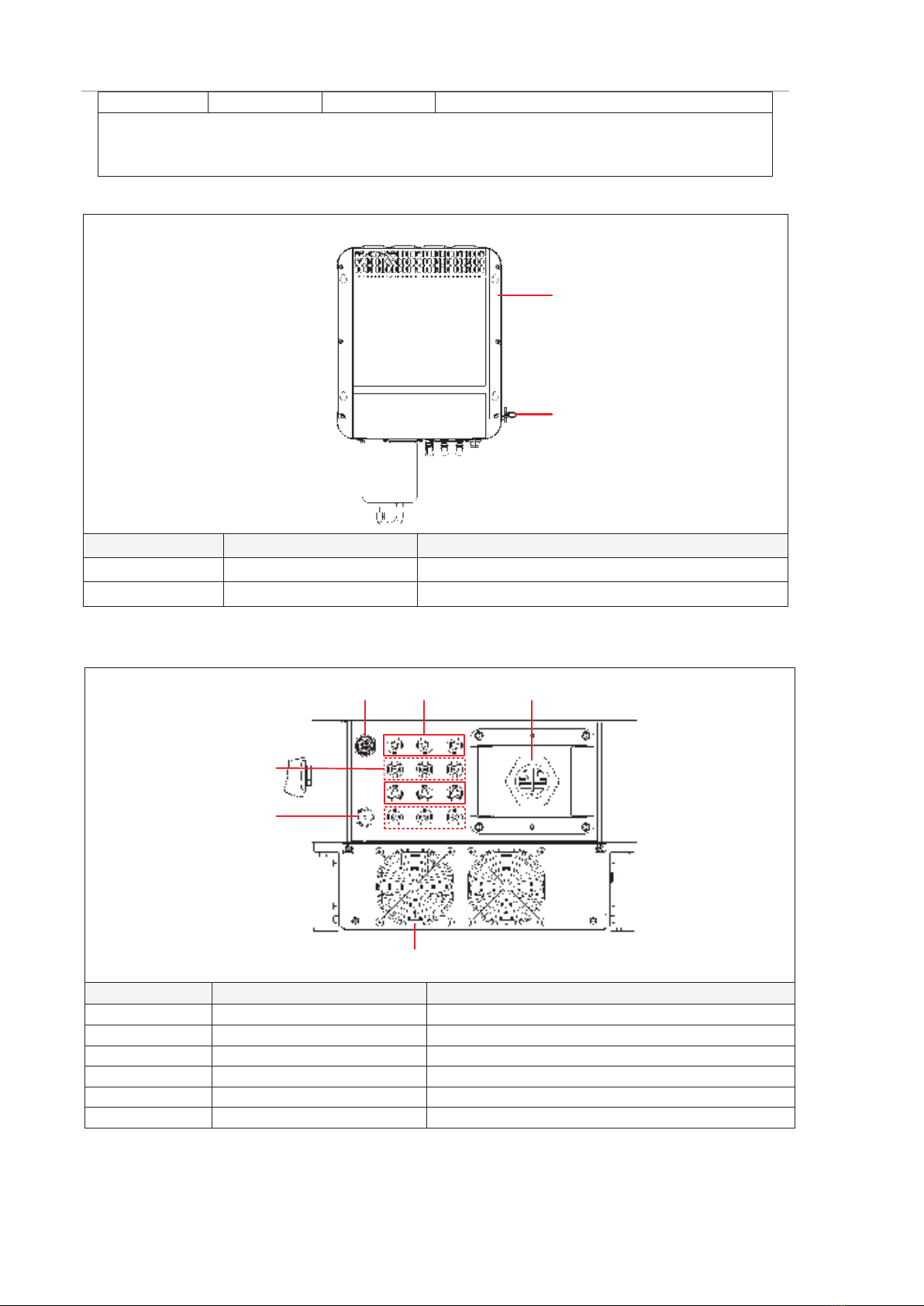
2.5 Machine Configuration
This section describes the internal components, back device, and bottom interface of the
string inverter. Bottom structure may differ from other models, the 30KTL is taken as an example
here.
CAUTION
There are components on the board that are sensitive to static electricity. Anti-static measures must be
taken before touching the board.
When touching the board, please be careful to avoid scratching the electrical components.
12
No.
Label
Component Name
1
LED indicator
2
AC cable shield
Figure 2-10 Front view of the inverter
The LED indicators from left toright are described as follows:
Table 2-1 LED Indicator Description
Indicator light Meaning Status Meaning
PV and grid
connection
Blue indicator
lights on
DC voltage is more than 200V and grid is connected
normally.
Blue indicator
flashes
DC voltage is more than 200V (grid is not
connected).
Blue indicator
lights off At least 1 PV array is normally connected.
On-grid
operation
Blue indicator
lights on The inverter is in the on-grid status.
Blue indicator
lights off The inverter is not connected to the grid.
Communication
indication
Blue indicator
flashes Normal communication.
Blue indicator
lights off Abnormal communication.
Alarm
indication
Red indicator
flashes slowly PID is operating.
Red indicator
flashes Abnormal alarm: regular alarm.
Red indicator
Critical alarm: faults.
User Manual of String Inverter
10
lights on
Remarks:
Slow flashis defined as: 1 second lights up, 2 seconds lights off.
Flashis defined as: 0.5 seconds lights up, 0.5 seconds lights off.
12
No. Label Component Name
1 Hanging Bracket
2 DC Switch
Figure 2-11 Back view of the inverter
123654
No.
Label
Component Name
1
1+ ~ 6+
PV+ terminals
2
1- ~ 6-
PV- terminals
3
Anti-backflow terminal
4
WiFi/GPRS communication interface
5
AC OUTPUT
AC terminal
6
Fan
Figure 2-12 Bottom view of the inverter
Note: Bluesun BSM8K-B/10K-B/12K-B has only 2 PV inputs at the bottom, Bluesun BSM 15K-B/17K-B
has 3 inputs, Bluesun BSM 20K-B/22K-B/25K-B has 4 inputs, and Bluesun BSM 30K-B/33K-B has 6
inputs. Bluesun models of 17K-B and below have no cooling fan at the bottom.
9

2 Product Description
2.6 Signs and labels
On the outer packaging of the product, there are some labels to guide the user to transport
and store the product. The meanings indicated by the labels are as follows:
Do not stack or
backlog
Handle with care and
avoid damage caused by
severe collision or friction
during transportation.
Forbid stampede
Pay attention to rain and
moisture-proof.
Stand upright and do
not tilt
Prohibition of tilting or
turning products
Front facing of the
inverter
Back facing of the
inverter
2.7 Warning Labels in Inverter
In order to ensure the safety of the person and property when using the product and to avoid
accidents, the following warning labels may be provided inside and outside the body of the string
inverter to remind the user of the safety precautions during operation.
PE: Here is the protective grounding terminal, requires reliable grounding to ensure the
safety of operators and equipment.
Warning: This component may present a hazard other than high voltage, which the user
should pay attention to.
High voltage hazard: This component may present a high voltage hazard and the user
must pay special attention.
Hot surface: Pay attention to the hot surface to prevent burns.
Refer to the user manual: Please refer to the corresponding instructions in the user
manual before operation.
Discharge identification: This equipment has an energy storage device. Before
maintenance, it is necessary to wait for the energy storage device to discharge to prevent
electric shock. The waiting time is not less than the indicated discharge time.
10
User Manual of String Inverter
12
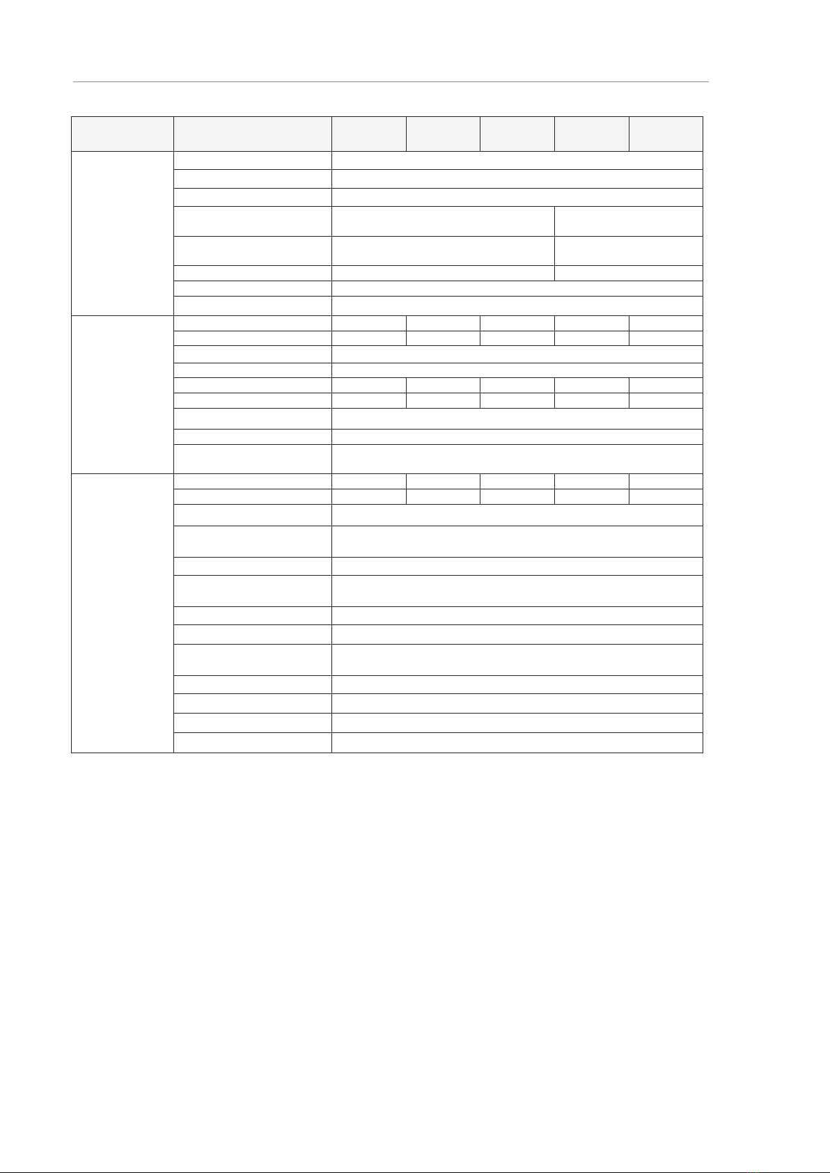
2.8 Technical Data
Model
Bluesun BSM 8K-B
Bluesun BSM 10K-B
Bluesun BSM 12K-B
Bluesun BSM 15K-B
Bluesun BSM 17K-B
DC parameters
Maximum DC voltage
1100V
Startup voltage
180V
MPPT voltage range
200V~1000V
MPPT full load working
voltage range
370V~850V 450V~850V
Maximum input current per
MPPT
20A/20A 26A/20A
Maximum input path
2
3
Number of MPPT
2
Back-feed current 0.5mA
AC parameters
Rated output power
8kW
10kW
12kW
15kW
17kW
Maximum active power
8.8kW
11kW
13.2kW
16.5kW
18.7kW
Rated grid voltage
400VAC
Allowable voltage range
300VAC~480VAC
Rated output current
11.6A
14.5A
17.4A
21.7A
24.6A
Maximum output current
12.7A
16A
19.1A
23.9A
27A
Rated grid frequency 50Hz/60Hz
Power factor
-0.8~+0.8
Total harmonic distortion
of current
<3%
System
parameters
Maximum efficiency
98.60%
98.60%
98.60%
98.61%
98.62%
European efficiency
98.30%
98.30%
98.30%
98.30%
98.30%
Insulation impedance test Supported
Residual leakage current
detection
Supported
String fault detection
Supported
Output over current
protection
Supported
Protection grade
IP65
Cooling mode
Natural cooling
Standby power
consumption
<1W
Display
LED indicators + APP
Communication interface
GPRS, 485RJ , Anti-backflow
DC terminal
MC4 plug-in terminal
AC terminal
OT terminal & Waterproof lock
11
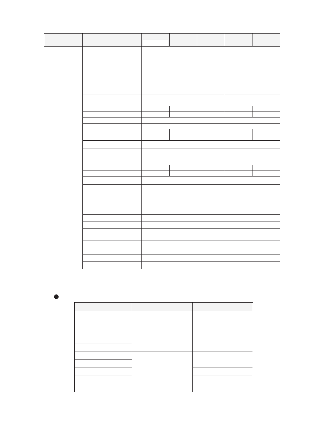
2 Product Description
Model
Bluesun
BSM 20K-B
Bluesun
BSM 22K-B
Bluesun
BSM 25K-B
Bluesun
BSM 30K-B
Bluesun
BSM 33K-B
DC parameters
Maximum DC voltage
1100V
Startup voltage
180V
MPPT voltage range
200V~1000V
MPPT full load working
voltage range
425V~850V
Maximum input current per
MPPT
30A/30A 40A/40A
Maximum input path
4
6
Number of MPPT
2
Back-feed current
0.5mA
AC parameters
Rated output power
20kW
22kW
25kW
30kW
33kW
Maximum active power
22kW
24.2kW
27.5kW
33kW
36.3kW
Rated grid voltage
400VAC
Allowable voltage range
300VAC~480VAC
Rated output current
28.9A
31.8A
36.1A
43.5A
47.6A
Maximum output current
37.8A
35A
39.7A
47.8A
52.4A
Rated grid frequency 50Hz/60Hz
Power factor
-0.8~+0.8
Total harmonic distortion
of current
<3%
System
parameters
Maximum efficiency
98.63%
98.65%
98.94%
98.60%
98.60%
European efficiency
98.30%
98.30%
98.26%
98.30%
98.30%
Insulation impedance test Supported
Residual leakage current
detection
Supported
String fault detection
Supported
Output over current
protection
Supported
Protection grade
IP65
Cooling mode
Intelligent air cooling
Standby power
consumption
<1W
Display
LED indicators + APP
Communication interface
GPRS, 485RJ , Anti-backflow
DC terminal
MC4 plug-in terminal
AC terminal
OT terminal & Waterproof lock
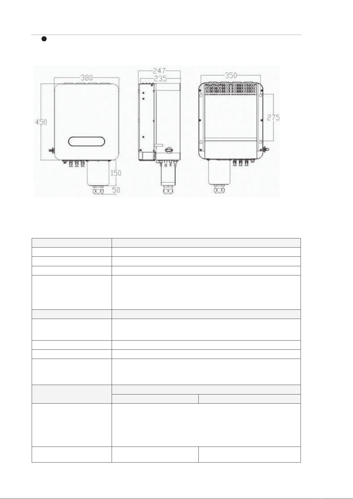
2.9 Mechanical Parameters
Size and weight
Model W*H*D (mm) Net weight (kg)
Bluesun BSM 8K-B
≤22
≤25
≤30
Bluesun BSM 10K-B
Bluesun BSM 12K-B
≤35
Note: size does not contain hangers, handles, pads, and so on. Dimensional error: ± 10mm.
Bluesun BSM 15K-B
Bluesun BSM 17K-B
Bluesun BSM 20K-B
Bluesun BSM 22K-B
Bluesun BSM 25K-B
Bluesun BSM 30K-B
Bluesun BSM 33K-B
12
380*400*247
380*450*247
User Manual of String Inverter
14
Inverter structure size
Note: The model shown in the picture below is 30KTL. The inverter sizes of other models are
similar, only the sizes of AC protection shell may be different.
Figure 2-13 Bluesun series inverter and hanging board size (left, front, back, unit: mm)
2.10 Ambient Requirements
Transportation environment Requirements
Type of shipping Waterways, railways, highways, aviation, etc.
Ambient temperature -40℃~+70℃
Relative humidity ≤95%when the temperature is +40℃
Mechanical conditions The vibration should not exceed the following limits:
2Hz≤f<9Hz, displacement 7.5mm;
9Hz≤f<200Hz, acceleration 20m/s2;
200Hz≤f<500Hz, acceleration 40m/s2;
Storage environment Requirements
Storage place Store in a warehouse with air circulation, no harmful gases, no flammable and
explosive substances, and no corrosive substances. Avoid strong mechanical
vibration and impact; stay away from strong magnetic fields.
Ambient temperature -40℃~+70℃
Relative humidity ≤95%
Mechanical conditions The vibration should not exceed the following limits:
10Hz≤f<57Hz, displacement 0.075mm;
57Hz≤f<150Hz, acceleration 10m/s2;
Working environment Requirements
Normal operating state Shut down state
Installation site Usually installed outdoors, at the bottom of the photovoltaic module.
Do not install the inverter in areas where flammable and explosive
substances are stored.
Avoid direct sunlight, rain and snow to extend the life of the inverter. It is
recommended to install in a sheltered place. If it can’t be satisfied,
please build a sunshade.
Ambient temperature -40℃~+60℃(After exceeding
45 ℃, the maximum continuous
-40℃~+70℃
13

2 Product Description
Transportation environment Requirements
input power and branch current
will be derated)
Relative humidity ≤100%, allow internal condensation
Altitude ≤4000m, must be derated above 4000m
Mechanical conditions Vibration should not exceed the following limits:
10Hz≤f<57Hz, displacement 0.075mm;
57Hz≤f<150Hz, acceleration 10m/s2;
-- Chapter end --
14

3 System installation
3.1 Unpack and inspection
After confirming that the outer packaging is intact, please perform unpacking inspection.
Unpack the box and check whether the appearance of the string inverter is good. When opening
the packing box, you need to use tools carefully to avoid scratching the string inverter;
The string inverter has been rigorously tested and inspected at the factory, but accidental
damage may occur during transportation, so please check the string inverter immediately after
receiving the goods. If you find any damage or omissions, please contact Bluesun Technology
as soon as possible, our staff will serve you as soon as possible.
3.2 Preparation of installation tools
Tool or equipment Use Remarks
4#Allen wrench Disassembly and assembly of the lower
door panel of the inverter
Phillips screwdriver (PH2) Loosen/tighten the screws of the output
terminals and baffles Bolt spec: M6,M8
Tube terminal crimping pliers Crimp the communication cable
terminal /
Socket wrench AC wiring Bolt spec: M8
MC4 Terminal crimping pliers Crimp MC4 terminal
The input cable needs to be crimped
into the MC4 terminal before it can
be connected to the PV + / PV-
terminal on the string inverter.
MC4 Removal tool Remove MC4 terminal /
Wire stripper Stripping wire /
Multimeter Measure voltage to ensure safety
during wiring and installation /
Safety protective equipment Labor protection necessary for
construction Insulation shoes, gloves, etc.
3.3 Installation environment requirements
The environmental requirements for the installation of string inverters are shown in "2.10
Ambient Requirements".
The installation method and position must be suitable for the weight and size of the string
inverter, see "2.9 Mechanical Parameters ".
The string inverter should be installed in a well-ventilated environment to ensure good heat
dissipation. Protect the inverter from direct sunlight, rain and snow can extend the life of the
inverter. It is recommended to choose a sheltered installation site. If it cannot be satisfied,
please build a sunshade (optional accessory).
During the operation of the string-type inverter, the temperature of the chassis and heat sink
will be relatively high, please installed the inverter in a location where it will not be accidentally
touched.
Note: This chapter takes Bluesun BSM 30K-B as an example to introduce the cable connection
methods for installation. The interfaces of other models may be a bit different, so please connect
cables according to actual situation while referring to this chapter.
15

User Manual of String Inverter
18
3.4 Requirements for reserved space
When installing string inverters, proper space must be reserved around the string inverters to
facilitate heat dissipation and maintenance.
≥500mm
≥300mm
≥500mm
≥
200mm
≥1000mm
Figure 3-1 Installation space of string inverter
When multiple string devices are installed on the same plane, it is recommended to install in a
straight line.
≥200mm ≥200mm
Figure 3-2 Installation space of string inverter
If you need to install it in two rows, it is recommended to install them in the shape of triangle.
≥100mm ≥300mm ≥100mm ≥300mm
Figure 3-3 Installation space of string inverter
16

3 System installation
3.5 Fixing method
WARNING
1. For precautions during inverter installation, please refer to "1 Safety Precautions"; for installation
environment requirements, please refer to "3.3 Installation environment requirements".
2. During installation, it must be confirmed that the on-site installation position can bear the total weight of the
inverter and accessories to avoid falling during installation or use.
3. It is recommended that four people work together to fix the inverter to avoid mechanical injury. During the
installation process, safety measures should be taken to prevent damage.
4. Please install it vertically or tilt it up to 15 ° backward to facilitate heat dissipation. Do not install the inverter
at an angle (tilt forward, tilt backward > 15 °, roll), horizontally, or upside down.
<15°
√√XX
5. If direct sunlight cannot be avoided, please add a sunscreen.
Installation steps
1. Refer to the fixed hole size of the inverter, use a drill with 100mm diameter to make holes
in the wall or bracket. The hole depth in the wall is about 80mm.
2. Unload 4PCS M6 casing reinforced expansion anchor into the wall holes, or use M6
combination bolts to pass it from the back to the front of the bracket. And use flat
washers/nuts to fix it in the front side.
Expansi on bolt(M8)
Dri l l on the wal l
Figure 3-4 Schematic diagram of drilling holes
3. Hang the inverter on the screw of the expansion bolt or combination screw,and use
spring washers/flat washers/nuts to fix it.
Expansi on boltSpring washer/
Fl at washer/Nut
Figure 3-5 Schematic diagram of wall-mounted (hoop) installation
17
This manual suits for next models
1
Table of contents
Other BlueSun Inverter manuals

Popular Inverter manuals by other brands

Mitsubishi Electric
Mitsubishi Electric 800 Series instruction manual

Xantrex
Xantrex Freedom SW 815-2024 owner's guide

Twin Disc
Twin Disc TECHNODRIVE TM 485-A1 operating manual

Latronics
Latronics PV Edge Grid 915-GI-72 user manual

Effekta
Effekta 10A/WRSL-12-1500 instruction manual

Haier
Haier AS12TA2HRA Service manual

ElectroDacus
ElectroDacus DSSR20 user manual

Xantrex
Xantrex 1200, 1750 owner's guide

Chicago Electric
Chicago Electric Power Systems 96706 Set up and operating instructions

DAH Solar
DAH Solar DHP60 5BB Series installation manual

SolarMax
SolarMax 360TS-SV Compact Station instruction manual

Lenze
Lenze 8200 series operating instructions


