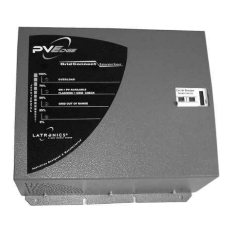
Latronics PV Edge Grid 915-GI-72 User manual

®

INTRODUCTION
Congratulations on purchasing the Latronics PV Edge Grid Interactive Inverter. Rapidly increasing interest in
the solar market has resulted in the latest advancement in inverter design allowing the feeding of electrical
power from photovoltaic solar panels directly into the grid. Using state of the art microprocessor controls
coupled with the reliability and safety of the proven toroidal transformer technology, LATRONICS is proud to
present this high quality, fully automatic Grid Connect Inverter.
We strongly suggest that you read through the next few pages of this manual, which explains all the
modes of operation and relevant safety precautions for your power Inverter.
**** Please remember to complete and return your warranty card****
INSTALLATION
Grid Interactive solar systems have become increasingly popular in recent years. These systems do not
require batteries for storage and have a very simple configuration.
Figure 1
Block diagram
BEFORE INSTALLATION:
• Ensure the Inverter has not been damaged in transit.
• The unit must be placed in a well ventilated and protected area, not exposed to the open environment, and
free from contaminates (ie exhaust gases, sea air, dust etc.).
• The PV edge is designed for indoor installation in a suitable location where ambient temperature will not
exceed rated values.
• As the PV edge has a wall mountable enclosure, ensure proper air circulation for cooling of the heat sink
on the rear.
LATRONIC SUNPOWER PTY LTD Doc. No: M61 www.latronics.com.au Page 2

• Before opening the case ensure the DC solar input and AC grid are disconnected.
• Due to the risk of electric shock from lethal voltages only authorised & suitably qualified personnel are
permitted to remove the cover.
• Safety- DC solar input and AC grid are electrically and galvanically isolated via the toroidal transformer.
DC WIRING:
• The Inverter is designed to operate on a photovoltaic supply only.
• It is recommended to externally install a DC switch or circuit breaker for disconnection of the PV solar input
in the case of fault of service.
• The DC solar input voltage is stated on the PV Edge compliance label and the technical specifications
sheet within this manual. Check that the input voltage is within the required limits and does not exceed
140VDC.
• Recommended minimum cable size for the DC Input is 4sqmm with an insulation rating of 0.6/1KV
• Observe Polarity
AC WIRING:
• The active Aand neutral N of the 240V AC output are electrically isolated from the solar input and earth
connections.
• The earth E is connected internally to the Inverter case.
• It is recommended to externally install a 10A circuit breaker for disconnection of the AC grid in the case of
installation, fault or service.
Figure 2
AC Output
Meter
A A
DC Input
+ -
AC Fuse 6.3A Antisurge (T) 20 x 5mm
on component side
link standard,
to be removed only when
optional AH Meter fitted
Mains
E N A
PV Edge internal wiring diagram
LATRONIC SUNPOWER PTY LTD Doc. No: M61 www.latronics.com.au Page 3

SOLAR INPUT CONFIGURATION
Panel Power
at 25°C
Module
Type
Number of
Panels Per
String
Number of
Strings
Solar Input Power
50W 12V 6 5 1500W
55W 12V 6 4 1320W
60W 12V 6 4 1440W
65W 12V 6 4 1560W
70W 12V 6 3 1260W
75W 12V 6 3 1350W
80W 12V 6 3 1440W
85W 12V 6 3 1530W
90W 12V 6 2 1080W
95W 12V 6 2 1140W
100W 12V 6 2 1200W
110W 12V 6 2 1320W
120W 12V 6 2 1440W
120W 24V 3 4 1440W
125W 12V 6 2 1500W
130W 24V 3 4 1560W
140W 24V 3 3 1260W
150W 24V 3 3 1350W
160W 24V 3 3 1440W
165W 24V 3 3 1485W
170W 24V 3 3 1530W
175W 24V 3 3 1575W
Note 1: The DC input is suitable for connection to solar modules only.
Note 2: Recommended Solar Input 1500W Absolute Maximum 1575W.
Note 3: Solar input must be configured for strings of 6x12V or 3x24V modules.
Note 4: Ensure that all solar modules are of the same type and brand to ensure the maximum power point and
voltage variation with temperature are consistent for all modules which will ensure maximum system output.
Note 5: Do not use different wattage modules in the same string, as the power is limited to the module of the
lowest rating. Eg. A string consisting of 1x50W and 5x100W modules will produce the same power output as
6x50W modules.
Note 6: Different wattage solar modules can be used in separate strings if all modules are of the same brand
and type in each string . Eg. 1 string of 6x75W (450W) plus another string of 6x75W (450W) plus a string of
6x100W (600W) would be acceptable and give a total of 1500W.
LATRONIC SUNPOWER PTY LTD Doc. No: M61 www.latronics.com.au Page 4

NVERTER OPERATION
The Inverter consists of a full bridge power stage utilising the latest generation of power MOSFET's, switching
a filter inductor and transformer tapping. The DC voltage of the solar input is switched at high frequency and
converted to an AC sinusoidal voltage and feed into the AC grid via the safety and isolation of the toroidal
transformer.
The sophisticated microprocessor control circuitry controls the switching of the power MOSFET's and
performs all the necessary checks of system parameters to ensure correct operation.
SPECIAL FEATURES
Night time disconnect
After dark when the solar input is no longer available the inverter will automatically disconnect from the AC
grid. This feature ensures that during the night, the inverter can not consume any power whatsoever while
remaining idle. Upon sunrise the next morning when solar input becomes available again, the PV edge will
automatically reconnect to the AC grid and begin generating power.
Parallel Operation
The PV edge automatically synchronises to the AC grid, therefore the output of multiple units can all be
connected together, and they will all be synchronised by the AC grid.
Note: The Solar inputs of multiple units cannot be paralleled.
Maximum Power Point Tracking
The optimum power level from the solar input depends on the available solar radiation and the temperature of
the solar modules. Even in cloudy weather with fluctuations in the solar radiation level, the PV edge constantly
monitors and tracks the optimum operating point to ensure maximum power from the solar modules is
achieved.
Protection
The AC grid supply is constantly monitored for under and over voltage, over and under frequency, and anti
islanding conditions via active phase shifts.
The DC input is protected against over voltage, reverse polarity and over current via very fast current limit
control.
Isolation between the DC input and AC output is achieved via the toroidal transformer.
The temperature of the transformer and switching devices are continuously monitored. The Inverter is fitted
with a cooling fan, which is temperature controlled and only operates when required.
Indicator Lamps
The five lights on the front panel indicate the inverter power level in increments of 20%.
Led 5 – 90% (top led)
Led 4 – 70%
Led 3 – 50%
Led 2 – 30%
Led 1 –10% (bottom led)
If the inverter were supplying 60% of full power then Leds 1, 2 & 3 would be illuminated.
Led 3 has two other modes of operation.
- This light will be on, (constant), when the Solar input power is present and the AC grid is disconnected or
the inverter is awaiting reconnection to the AC grid.
- This light will flash for 90 seconds when the inverter connects to the AC grid and performs a voltage and
frequency stability check before feeding power into the AC grid.
- When Led 3 is in either of these 2 modes all other Leds will be OFF.
LATRONIC SUNPOWER PTY LTD Doc. No: M61 www.latronics.com.au Page 5

FAULT FINDING
Should the Inverter appear to be malfunctioning we suggest the following to eliminate any external problems.
1. Turn the Inverter “OFF” by disconnecting the DC Solar input and then disconnecting the AC grid.
2. Reconnect the DC Solar Input. All lights on the inverter should come ON for 1 second on power up and
then go OFF. The centre or 3rd light should remain ON to indicate the solar input is available. Solar input
voltage needs to be >100V for the light to turn ON. If the light does not illuminate check Solar Input for
correct operation.
3. Next reconnect the AC grid. After 10 seconds the centre or 3rd light should begin flashing to indicate
inverter reconnection to the AC grid. The light will flash for approx 90 seconds while the PV edge checks
the mains voltage and frequency are stable. Should the light not begin flashing check if the AC grid is
present. Also check internal fuse at top of circuit board above AC terminal block. (see Figure 2)
4. After the 3rd light stops flashing the inverter will begin feeding power into the AC grid.
Helpful Hints
• Make certain that you understand the operation of the Inverter.
• Remember that it has automatic reconnection to the AC grid.
• Make sure leads and terminals are not corroded, loose or faulty in any way.
• Make sure circuit breakers or switches are reset properly. If unsure switch OFF and ON again.
WARNING:
Due to dangerous voltages existing inside the unit only
authorised personnel are permitted to open or service the
Inverter.
Inverters are supplied by the manufacturer or the
manufacturers agents under the express condition that no
responsibility is implied or accepted by the above parties for
any damage to any appliance, equipment or property
associated with the correct or otherwise operation of the
Inverter. Contravention of any of the above conditions
automatically invalidates warranty.
LATRONIC SUNPOWER PTY LTD Doc. No: M61 www.latronics.com.au Page 6

WARRANTY CONDITIONS
All conditions and warranties expressed or implied by statute, the common law equity trade custom or usage
or otherwise howsoever are hereby expressly excluded to the maximum extent permitted by law. Where so
permitted the liability of Latronic Sunpower Pty. Ltd. for a breach of condition or warranty that cannot be
excluded is limited (at Latronic Sunpower Pty. Ltd. ‘s option) to the replacement or repair of the goods or the
supply of equivalent goods or the cost of replacing or repairing the goods or of acquiring equivalent goods.
Latronic Sunpower Pty. Ltd. shall not be liable in any way whatsoever for indirect or consequential loss or
damage whatsoever (whether based on tort or contract or otherwise).
• Damage caused by unauthorised repair, alteration or substitution of non-standard parts, incorrect
installation, misuse, negligence, accident or similar cause, or usage other than in accordance with the
operating instructions, is not covered under Warranty.
• The Company may, at its discretion, agree to act as agent for the owner where delivery is requested and
all costs for cartage and insurance will be for the owner’s account.
• The replacement of any part or labour involved will not have the effect of extending the period of the
warranty of the goods.
• Any faulty part replaced under Warranty becomes the property of the Company for purposes of
examination and claim under proprietary Warranty.
• Keep your receipt as proof of purchase, should any difficulties arise concerning the return of the
registration card.
LATRONIC SUNPOWER PTY LTD Doc. No: M61 www.latronics.com.au Page 7

TECHNICAL SPECIFICATIONS
Input Data
Recommended Solar Input Power @25C 1500W
Maximum DC Input Current 18A
Maximum DC Input Voltage 150V
Maximum Power Point Tracking Range 85-140VDC
Automatic Turn ON 100VDC
Starting Operation 10W
Number of Modules per String 6 x 12V modules
Reverse Polarity Protection Short circuit diode across DC input terminals
Output Data
Output Power 1300W max (current limited)
Output Voltage Range 205-265Vac
Output Frequency 50Hz tolerance +/- 1Hz
Output Current Harmonic Distortion <4%
Power Factor 1
Peak Efficiency 93%
Night Time Power Consumption 0W Automatically disconnects from AC grid
Input/Output Isolation 3500V via Toroidal Transformer
Operating Temperature -10 to 50C
Anti islanding Protection Over/under voltage & over/under frequency
& active phase shift
General Data
Status Indicators Output power in 20% increments
Solar Input ON
Grid Monitoring – Stability check
Wall Mount Enclosure 3mm Powder Coated Aluminium
Dimensions 420mm high x 320mm wide x 160mm deep
Weight 17Kg
Connections 10mm Terminal Block
Warranty 2 years
Standards
ESAA Approval No.51973
c-tick
AS3000
EN55014
Certificate of Suitability
LATRONIC SUNPOWER PTY LTD Doc. No: M61 www.latronics.com.au Page 8

LATRONIC SUNPOWER PTY LTD Doc. No: M61 www.latronics.com.au Page 9
DECLARATION OF CONFORMITY
Manufacturer : Latronic Sunpower Pty Ltd
ABN : 97 010 707 169
Address : PO Box 73 , Moffat Beach , QLD 4551, Australia
Product : 1500W PV Edge DC to AC Grid Interactive Inverter
Model : 912-GI-72
The product listed above conforms to the following Standards
C-Tick mark for the EMC emission standard EN55014.
ESSA approval to Australian Grid Connect Guidelines approval No. No.51973
Safety Certificate for mains connected apparatus Approval No. Q01307
Bradley Cowin
Development Engineer
2.08.2001
Table of contents
Other Latronics Inverter manuals
Popular Inverter manuals by other brands

Hitachi
Hitachi WJ200 Series Software Quick reference guide

Huawei
Huawei iSitePower-M ISP-M-MAB05B1 manual

Delios
Delios DLS 300C installation guide

PAW
PAW SolarBloC midi 2D Installation and commissioning instructions

Troy-Bilt
Troy-Bilt 5500 Watt quick start guide

Saftronics
Saftronics CIMR-VG5U Installation & Quick Start Manual