BlueWalker VFI CPG PF1 3/3 400V 30K User manual

VFI CPG PF1 3/3 400V
30K/ 60K/ 100K/ 120K/ 180K/ 200K
VFI CPG PF1 3/3 208V
15K/30K/ 50K/ 60K/ 90K/ 100K
Online UPS
Uninterruptible Power Supply System
User Manual

Version:1.5

Please comply with all warnings and operating
instructions in this manual. This equipment
should only be installed, serviced, and
maintained by qualified personnel. Do not
operate this unit before reading through all
safety information and operating instructions
carefully.
Disclaimer
We assume no responsibility or liability for loss or damages, whether direct, indirect,
consequential or incidental, which might arise out of the use of such information. The use of
any such information will be entirely at the user’s risk. Information in this manual is subject to
change without notice. We make no commitment to update or keep current the information in
this manual. If you find information in this manual that is incorrect, misleading, or incomplete,
we would appreciate your comments and suggestions.

Table of Contents
1. SAFETY AND EMC INSTRUCTIONS ................................................................................................. 1
1-1. TRANSPORTATION AND STORAGE...............................................................................................................1
1-2. PREPARATION.......................................................................................................................................1
1-3. INSTALLATION ......................................................................................................................................1
1-4. CONNECTION WARNINGS...............................................................................................................2
1-5. OPERATION .........................................................................................................................................3
1-6. STANDARDS .........................................................................................................................................3
2. INSTALLATION AND OPERATION .................................................................................................. 4
2-1. UNPACKING AND INSPECTION ...................................................................................................................4
2-2. WIRING TERMINAL VIEW ........................................................................................................................5
2-3. UPS POSITIONING ................................................................................................................................9
2-4. SINGLE UPS INSTALLATION ...................................................................................................................10
2-5. UPS INSTALLATION FOR PARALLEL SYSTEM................................................................................................12
2-6. SOFTWARE INSTALLATION .....................................................................................................................14
3. OPERATIONS................................................................................................................................ 15
3-1. INITIAL OPERATION.............................................................................................................................15
3-2. SCREEN DESCRIPTION ..........................................................................................................................15
3-3. AUDIBLE ALARM..................................................................................................................................39
3-4. SINGLE UPS OPERATION ......................................................................................................................40
3-5. PARALLEL OPERATION ..........................................................................................................................43
3-6. FAULT CODE ......................................................................................................................................44
3-7. WARNING CODE .................................................................................................................................46
4. TROUBLE SHOOTING ................................................................................................................... 47
5. STORAGE AND MAINTENANCE ....................................................................................................................48
5-1. STORAGE ..........................................................................................................................................48
5-2. MAINTENANCE....................................................................................................................................48
6. SPECIFICATIONS ......................................................................................................................... 49

1
1. Safety and EMC instructions
All safety instructions in this document must be read, understood and followed.
1-1. Transportation and Storage
Please transport the UPS system only in the original packaging to protect against shock and
damage.
The UPS must be stored in the room where the temperature is well regulated. Ambient
temperature should not exceed 40°C.
1-2. Preparation
Condensation may from if the UPS system is moved from cold to warm environment immediately.
The UPS system must be absolutely dry before being installed. Please allow at least two hours for
the UPS system to acclimate the environment.
Do not install the UPS system near water or in moist environments.
Do not install the UPS system where it would be exposed to direct sunlight or nearby heat
source.
Do not block ventilation holes on the UPS housing.
1-3. Installation
Do not connect appliances or devices which would overload the UPS (e.g. big motor-type
equipment) to the UPS output terminal.
Place cables in such a way that no one can step on or trip over them.
Do not block air vents on the housing of the UPS. Ensure proper unit spacing of ventilation.
UPS equipped with grounding terminal, in the final installation phase, connect grounding/
earthing wire to the external UPS battery cabinets or appropriate grounding terminals.
The UPS can be installed only by qualified maintenance personnel.
An appropriate disconnect device such as short-circuit backup protection should be incorporated
during installation.
An integral emergency shutoff switch which prevents additional load from the UPS in any mode
of operation should be implemented during the installation.
Secure the grounding/earthing wire before connecting to any live wire terminal.
Installation and Wiring must be in accordance with the local electrical laws and regulations.

2
1-4. Connection Warnings
•There is no standard backfeed protection inside of the UPS. However, there are relays on the Input to
cut off line voltage and while the neutral is still connected to UPS.
Main
Input
Input Rly
UPS
L1
L2
L3
N
Bypass
Input
Input Rly
L1
L2
L3
N
Input relay diagram
•This UPS should be connected with TN grounding/earthing system.
•The power input for this unit must be three-phase rated in accordance with the equipment nameplate. It
also must be suitably grounded.
•Use of this equipment in medical instrument of any life-sustaining equipment where failure of this
equipment can reasonably be expected to cause the failure of the life-sustaining equipment or to
significantly affect its safety or effectiveness is not recommended. Do not use this equipment in the
presence of a flammable mixture with air, oxygen or nitrous oxide.
•Connect grounding terminal of UPS to a grounding electrode conductor.
•In accordance with safety standard EN-IEC 62040-1, installation has to be provided with a《Backfeed
Protection》system, as for example a contactor, which will prevent the appearance of voltage or
dangerous energy in the input mains during a mains fault (see figure 24 and respect the wiring diagram
of «Backfeed Protection» depending if the equipment is with signal or three phase input).
There can be no derivation in the line that goes from the «Backfeed Protection» to the UPS, as
the standard safety would be infringed.
•Warning labels should be placed on all primary power switches installed in places away from the unit to
alert the electrical maintenance personnel of the presence of a UPS in the circuit. The label will bear the
following or an equivalent text:
Before working on this circuit
-Isolate Uninterruptible Power Supply (UPS)
-Then check for Hazardous Voltage between all terminals including the protected
earth
Risk of Voltage Backfeed
WARNING
HIGH LEAKAGE CURRENT
EARTH CONNECTION ESSENTIAL
BEFORE CONNECTING SUPPLY
3
1-5. Operation
Do not disconnect the grounding/earthing conductor cable on the UPS or the building wiring
terminals under any circumstance.
The UPS system features its own, internal current source (batteries). The UPS output sockets or
output terminal blocks may be electrically live even if the UPS system is not connected to the building
mains/live wires. (only for standard models)
In order to fully disconnect the UPS system, first press the “OFF” button and then disconnect the
mains/live wires.
Ensure that no liquid or other foreign objects can enter into the UPS system.
The UPS can be operated by any individuals with no previous experience.
1-6. Standards
* Safety
IEC/EN 62040-1
* EMI
Conducted Emission...............................:IEC/EN 62040-2
Category C3
Radiated Emission..................................:IEC/EN 62040-2
Category C3
*EMS
ESD.........................................................:IEC/EN 61000-4-2 CD Level 2
AD Level 3
RS........................................................ ...:IEC/EN 61000-4-3
Level 3
EFT......................................................... :IEC/EN 61000-4-4
Level 3
SURGE................................................... :IEC/EN 61000-4-5
Level 3
CS........................................................... :IEC/EN 61000-4-6
Level 3
Power-frequency Magnetic field.............. :IEC/EN 61000-4-8
Level 4
Low Frequency Signals............................:IEC/EN 61000-2-2 10V
Warning:
This is a product for commercial and industrial application in the
second environment-installation restric
tions or additional measures may be
needed to prevent disturbances.

4
2. Installation and Operation
These series came with two VAC systems: 208V and 400V. There are two different types of models: standard
and long-run models. Please refer to the following table.
VAC System
Model
Type
Model
Type
208V LV15K
Standard
model
LV 15KL
Long-run
model
LV 30KL
LV 50KL/ 60KL
LV 90KL/100KL
400V HV30K
HV 30KL
HV 60KL
HV100KL/120KL
HV 180KL/200KL
We also offer optional parallel function. The UPS with parallel function is called the “Parallel model”. We have
detail installation and operation procedure of the Parallel Model in the following chapter.
2-1. Unpacking and Inspection
Unpack the package and check the package contents. The shipping package should contain:
● One UPS
●One user manual
● One monitoring software CD
●One RS-232 cable (option)
●One USB cable
●One parallel cable (only available for parallel model)
●One shared current cable (only available for parallel model)
NOTE: Before the installation, please inspect the unit. Be sure that there is no physical damage to the unit.
Do not turn on the unit and notify the carrier and dealer immediately if there is any damage or missing parts
and accessories. Please keep the original packaging for future use. It is recommended to keep each
equipment and battery set in their original packaging because they have been designed to provide maximum
protection during transportation and storage.

5
2-2. Wiring Terminal View
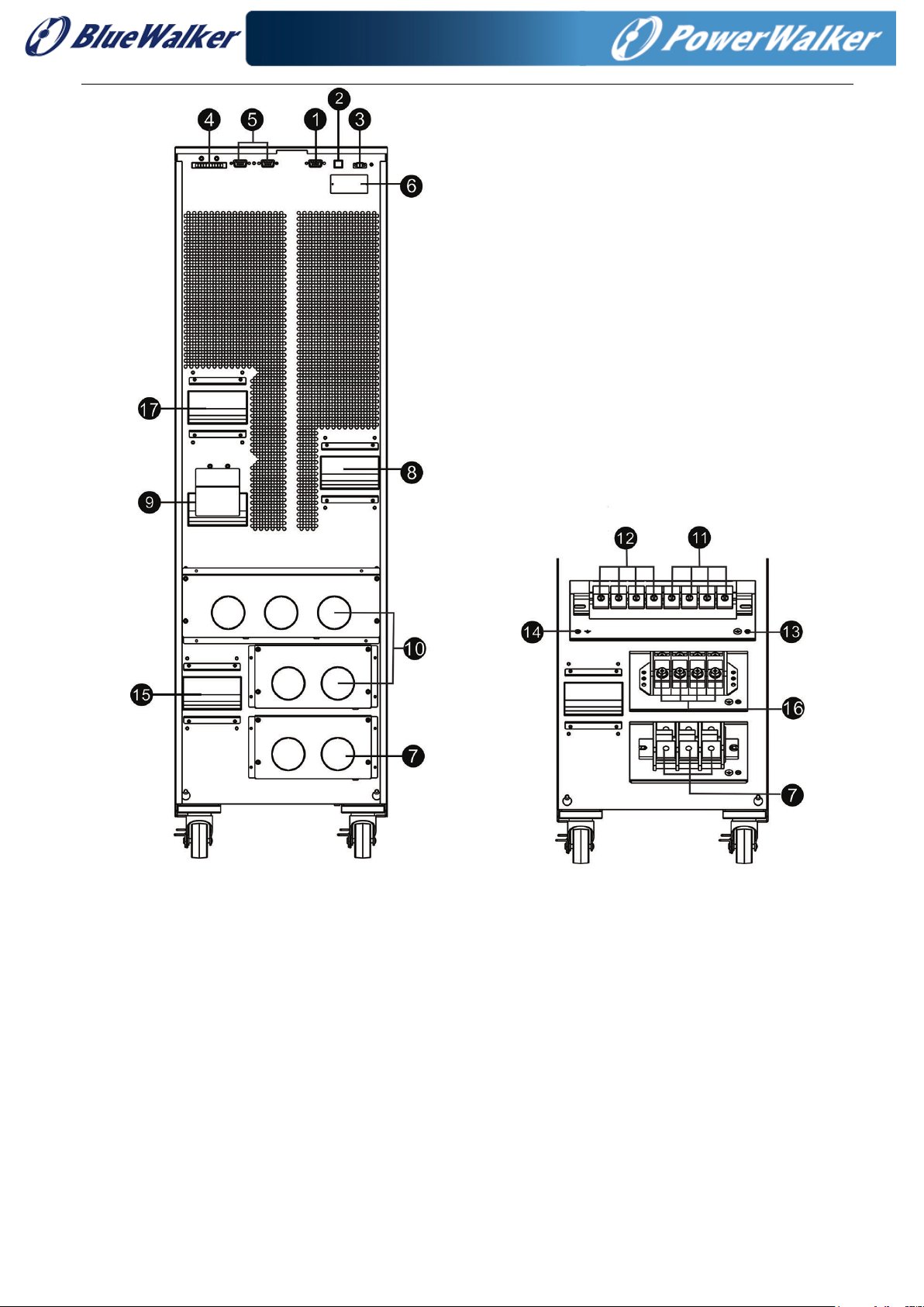
Diagram 1: HV 30K/LV 15K rear panel
6
Diagram 2: HV 60KL/LV 30KL rear panel Diagram 3: HV 60KL/LV 30KL
input/output terminal
7
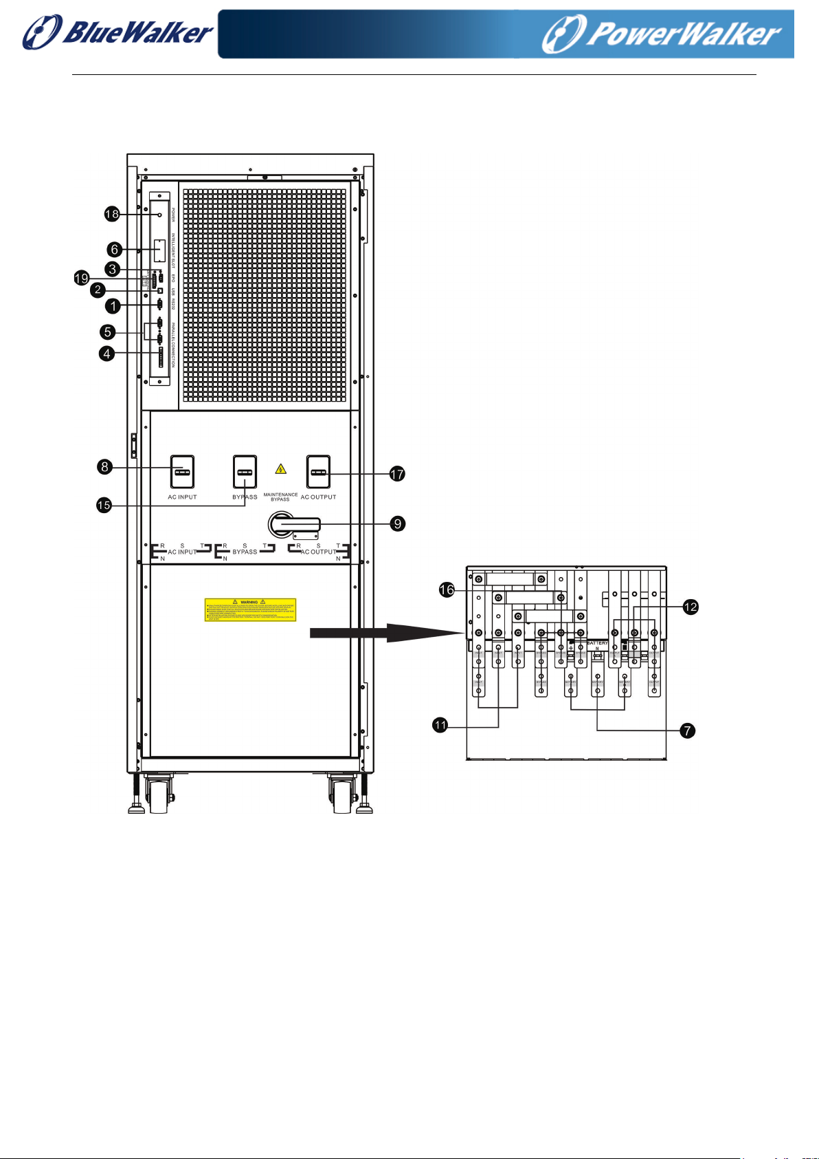
Diagram 4: HV 100KL /HV 120KL/LV 50KL/LV 60KL Diagram 5: HV 100KL/HV 120KL/ LV
front door open view 50KL/LV 60KL terminal view
8
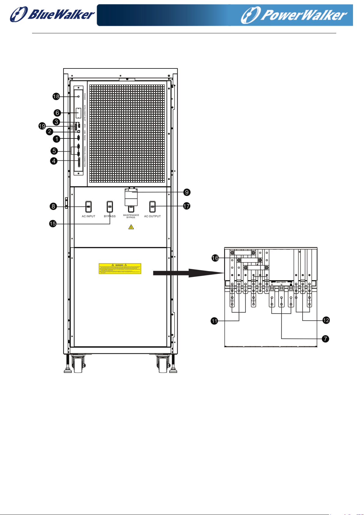
Diagram 6: HV 180KL /HV 200KL/LV 90KL/LV 100KL Diagram 7: HV 180KL /HV 200KL/LV
front door open view 90KL/LV 100KL terminal view
1. RS-232 communication port
2. USB communication port
3. Emergency power off function connector (EPO connector)
4. Share current port
5. Parallel port
6. Intelligent slot
7. External battery connector/terminal
8. Line input circuit breaker/switch
9. Maintenance bypass switch
9
10. Input/Output terminal
11. Line input terminal
12. Output terminal
13. Input grounding terminal
14. Output grounding terminal
15. Bypass input circuit breaker/switch
16. Bypass input terminal
17. Output switch
18. Cold start function button
19. Dry contact communication port
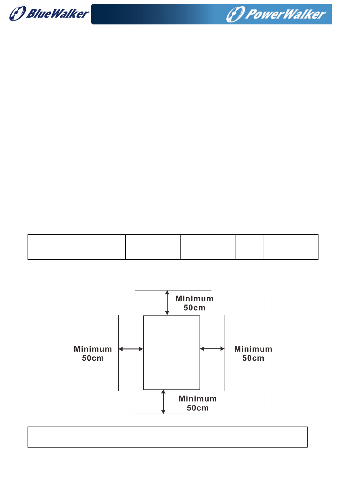
2-3. UPS Positioning
The UPS should be installed in the environment with free ventilation, less dust, optimum ambient
temperature and humidity.
The recommended ambient temperature is 20°C~25°C with 50% humidity.
Ambient temperature: 0°C~+40°C
Storage temperature: -15ºC ~ 60ºC
Relative humidity: 0 ~ 95%
Altitude: If the UPS is installed within 1000m, the UPS power will not be derated. When the height is
over 1000m, the output power will be derated by following the table.
Altitude(m) 1000 1500 2000 2500 3000 3500 4000 4500 5000
Coefficient 100% 95% 91% 86% 82% 78% 74% 70% 67%
Vertical: No vibration and the degree of deviation from vertical shouldn’t be more than 5°.
Space: It’s requested to have a clearance of approx. 50 cm to the front and back of the unit and approx.
50 cm to the side.
Caution! It’s NOT allow to have flammable, explosive or corrosive gas or liquid in installation
environment. It is forbidden to install in a metal conductive dust environment.

10
2-4. Single UPS Installation
Installation and wiring must be carried out in accordance with the local electric laws and regulations by
trained professionals.
1) Make sure that the mains wire and breakers of the building are rated for the capacity of the UPS to
prevent electric shock or risk of fire.
NOTE: Do not use the wall receptacle as the input power source for the UPS, as its rated current is less than
the UPS’s maximum input current. The receptacle may be damaged and destroyed.
2) Switch off the mains switch in the building before installation.
3) Turn off all the connected devices before connecting to the UPS.
4) Prepare wires based on the following table:
Model
Wiring spec (AWG)
Input(Ph)
Output(Ph)
Neutral
Battery
Ground
HV30KL
LV15KL
8 8 4 4 4
HV30K
LV15K
8 8 4 4
HV60KL
LV30KL
4 4 1 1 1
HV100KL
LV50KL
1 1 2/0 2/0 2/0
HV120KL
LV60KL
1/0 1/0 3/0 3/0 3/0
HV180KL
LV90KL
3/0 3/0 3/0*2pcs 3/0*2pcs 3/0*2pcs
HV200KL
LV100KL
1*2pcs 1*2pcs 3/0*2pcs 3/0*2pcs 3/0*2pcs
NOTE 1: The cable for HV30KL/HV30K/LV15KL/LV15K should be able to withstand over 60A current.
It is recommended to use AWG 8 or thicker wire for Phase and AWG 4 or thicker wire for Neutral for
safety and efficiency.
NOTE 2: The cable for HV 60KL/LV 30KL should be able to withstand over 107A current. It is
recommended to use AWG 4 or thicker wire for Phase and AWG 1 or thicker wire for Neutral for safety
and efficiency.
NOTE 3: The cable for HV 100KL/LV 50KL should be able to withstand over 184A current. It is
recommended to use AWG 1 or thicker wire for Phase and AWG 1 or thicker wire for Neutral for safety
and efficiency.
NOTE 4: The cable for HV 120KL/LV 60KL should be able to withstand over 211A current. It is
recommended to use AWG 1/0 or thicker wire for Phase and AWG 3/0 or thicker wire for Neutral for
safety and efficiency.
NOTE 5: The cable for HV 180KL/LV 90KL should be able to withstand over 324A current. It is
recommended to use AWG 3/0 or thicker wire for Phase and AWG 3/0*2pcs or thicker wire for Neutral
for safety and efficiency.
NOTE 6: The cable for HV 200KL/LV 100KL should be able to withstand over 357A current. It is
recommended to use AWG 1*2pcs or thicker wire for Phase and AWG 3/0*2pcs or thicker wire for
Neutral for safety and efficiency.
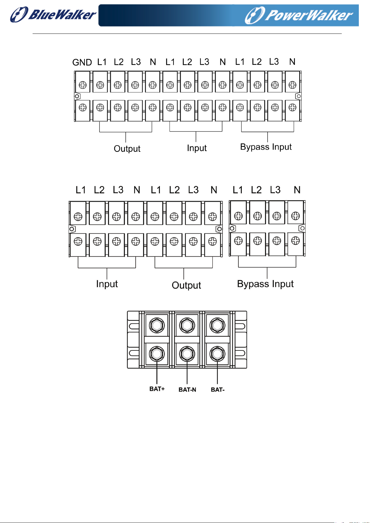
5) Remove the terminal block cover at the rear panel of UPS. Then connect the wires according to the
11
following terminal block diagrams: (Connect the grounding/earthing wire first when making wire
connections. Disconnect the earth wire after disconnect the power wire.)
Terminal block wiring diagram for HV 30KL /LV 15KL
Terminal block wiring diagram for HV 60KL/ LV 30KL
Battery terminal block wiring diagram for HV 60KL/ LV 30KL

12
Terminal block wiring diagram for HV 100KL /120KL/ 180KL/ 200KL &
LV 50KL/60KL/90KL/100KL
NOTE 1: Make sure that the wires are connected tightly with the terminals.
NOTE 2: Please install the output breaker between the output terminal and the load, and the breaker
should be qualified with leakage current protective function if necessary.
6) Put the terminal block cover back at the rear panel of the UPS.
Warning:
● Make sure a DC breaker or other protective device between UPS and the external battery pack is
installed. If not, please install it carefully. Switch off the battery breaker before installation.
NOTE: Set the battery pack breaker in “OFF” position and then install the battery pack.
● Pay highly attention to the rated battery voltage marked on the rear panel. If you want to change the
numbers of the battery pack, please make sure you modify the setting simultaneously. The Connection
with wrong battery voltage may cause permanent damage of the UPS. Make sure the voltage of the
battery pack is correct.
● Pay highly attention to the polarity marking on external battery terminal block. And make sure the
correct battery polarity is connected. Wrong connection may cause permanent damage of the UPS.
● Make sure the protective earth ground wiring is correct. The wire current spec, color, position,
connection and conductance reliability should be checked carefully.
● Make sure the utility input & output wire is correct. The wire current spec, color, position, connection and
conductance reliability should be checked carefully. Make sure the L/N side is correct, not reverse or
short-circuited.
2-5. UPS Installation for Parallel System
If the UPS is only available for single operation, you may skip this section to the next.
1) Install and wires the UPS according to the section 2-3.
2) Connect the output wires of each UPS to an output breaker.
3) Connect all output breakers to a major output breaker. Then this major output breaker will directly
connect to the loads.
4) Common battery packs or independent battery packs are allowed.
13
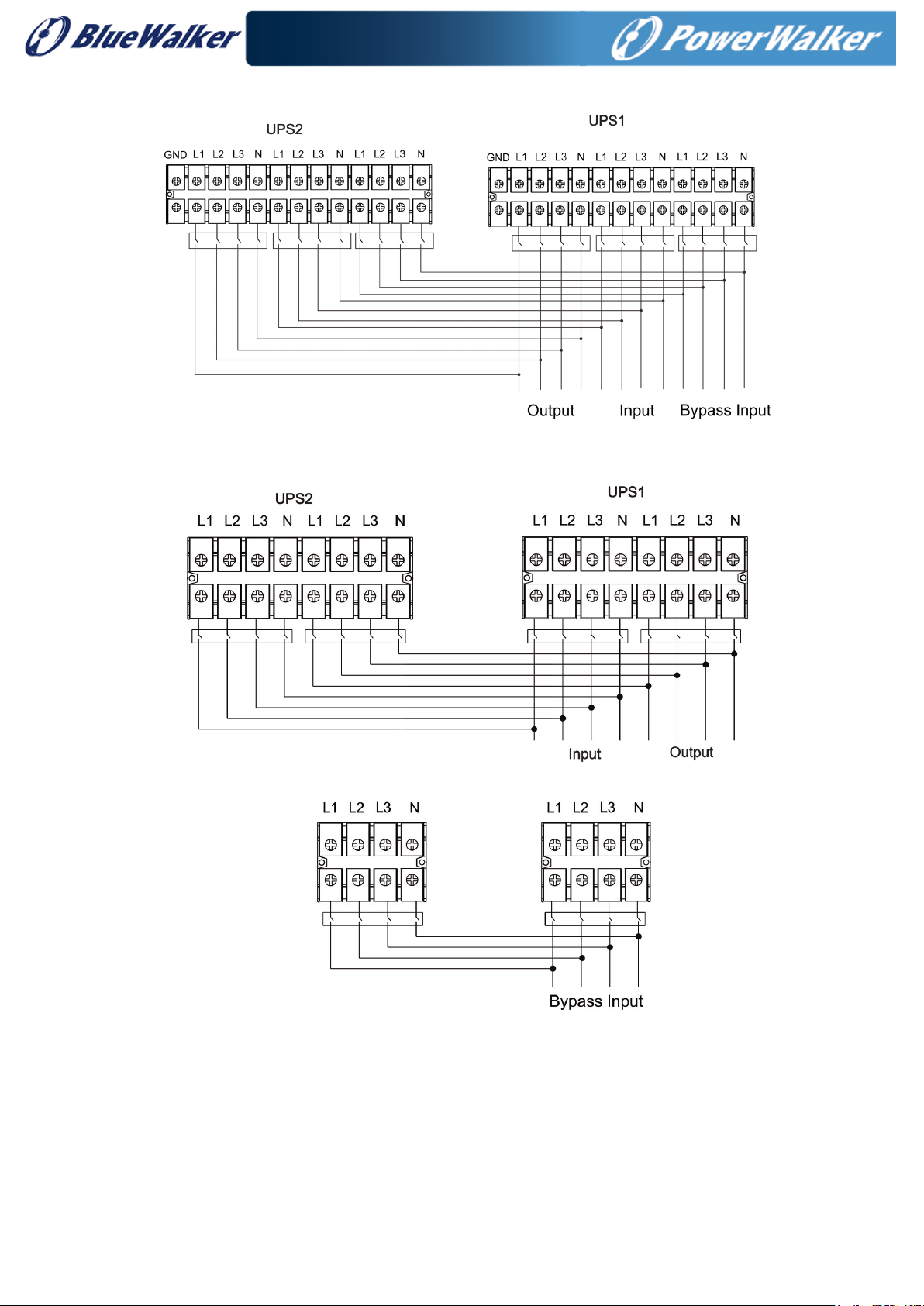
5) Refer to the following wiring diagram:
Wiring diagram of parallel system for HV30KL/LV15KL
Wiring diagram of parallel system for HV 60KL/LV 30KL
14
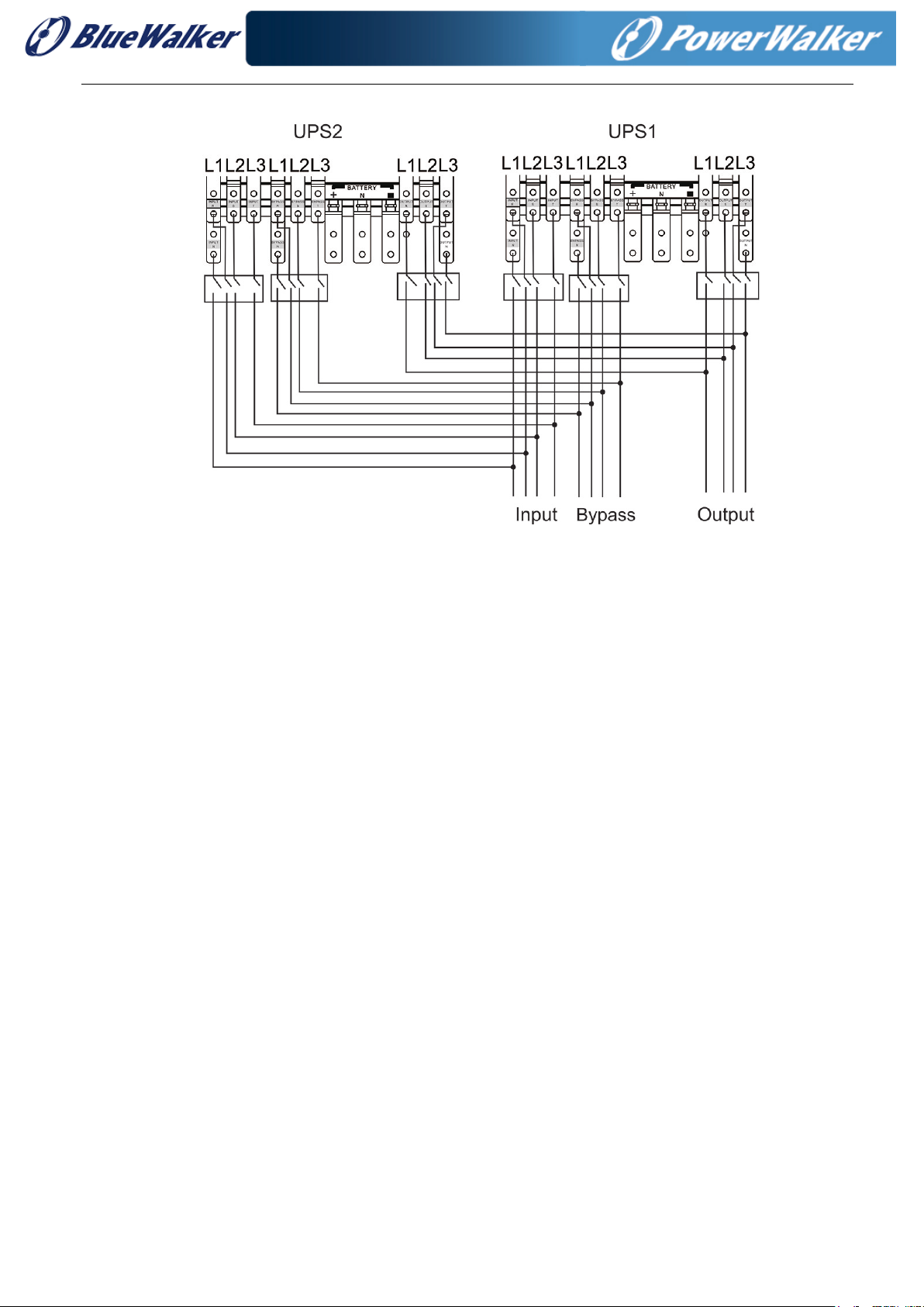
Wiring diagram of parallel system for HV 100KL / 120KL/ 180KL/ 200KL &
LV 50KL / 60KL / 90KL / 100KL
2-6. Software Installation
For optimal computer system protection, install UPS monitoring software to configure UPS shutdown
operation.
15
3. Operations
3-1. Initial Operation
1) Before operation, make sure that the two strings of batteries are connected correctly in order
of ”+,GND,-” terminals and the breaker of the battery pack is at “ON” position (only for long-run
model).
2) Press the “ ” button to set up the power supply for the UPS. UPS will enter to power on
mode. After initialization, UPS will enter to “No Output mode”.
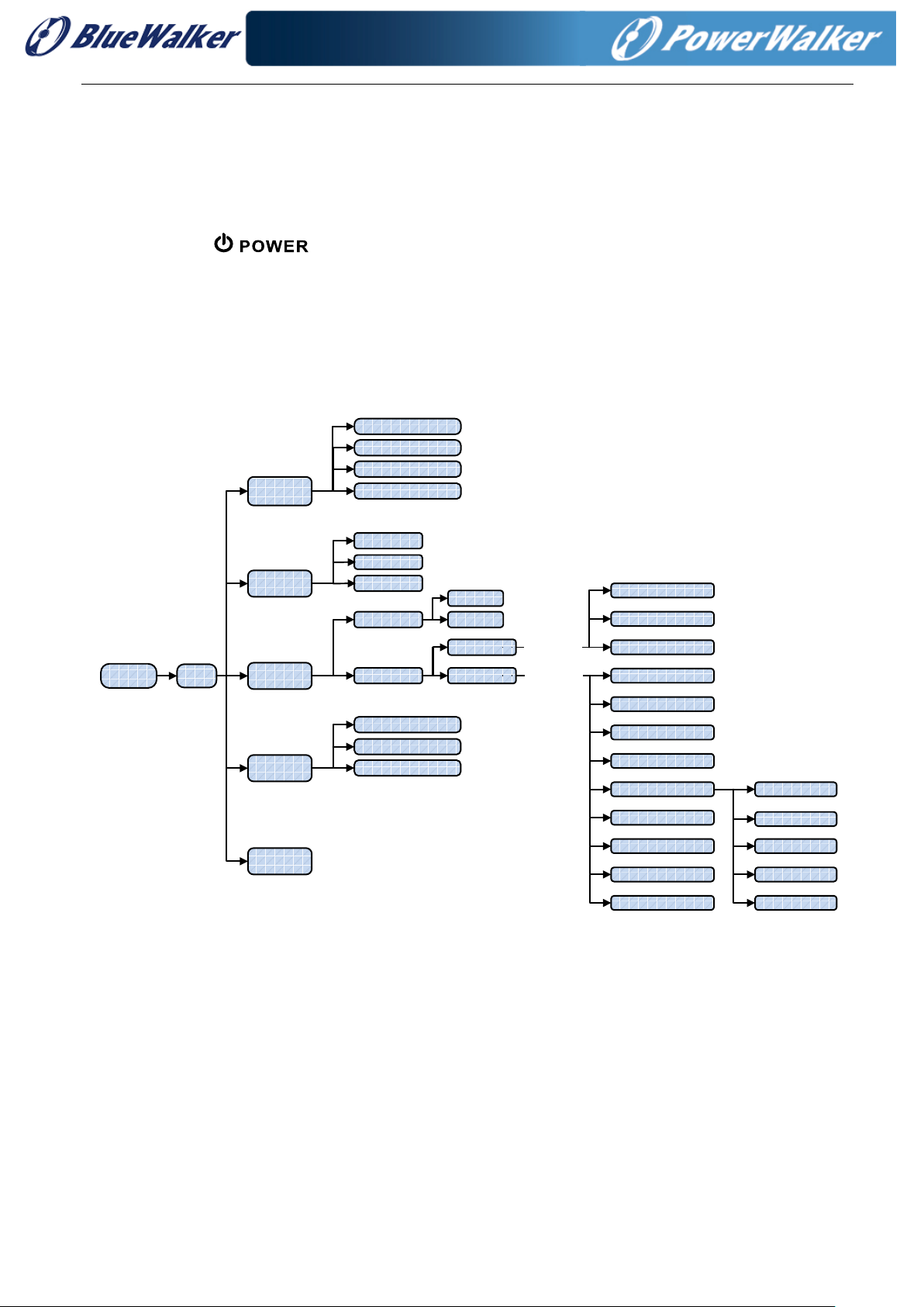
3-2. Screen description
After initialization, the LCD will display main screen. There are five sub-menus: Control, measure, setting,
information and data log. Touch any sub-menu icon to enter into the sub-screen.
MAIN
Initializing
CONTROL
DATA LOG
MEASURE
ON/OFF UPS
BATTERY TEST
MUTE ALL
MEASURE1
MEASURE2
MEASURE3
GENERAL
BASIC1
BASIC2
SETTING
INFO
ON/OFF CHARGER
DATALOG
PARAMETERS
CALIBRATION
EEPROM
TOUCH
SYS PARAMETER
P ASS WO RD:****
INSTALL INFO
VOL CALI
CURR CALI
INITIAL
ELECTRICAL
BATTERY
MISCELLANEOUS
UPS SELFTEST
ELECTRICAL
BATTERY
MISCELLANEOUS
P ASS WO RD:0000
PARAMETER INFO
RATED INFO
BASIC INFO
ADVANCE
User
Maint ainer
Menu tree
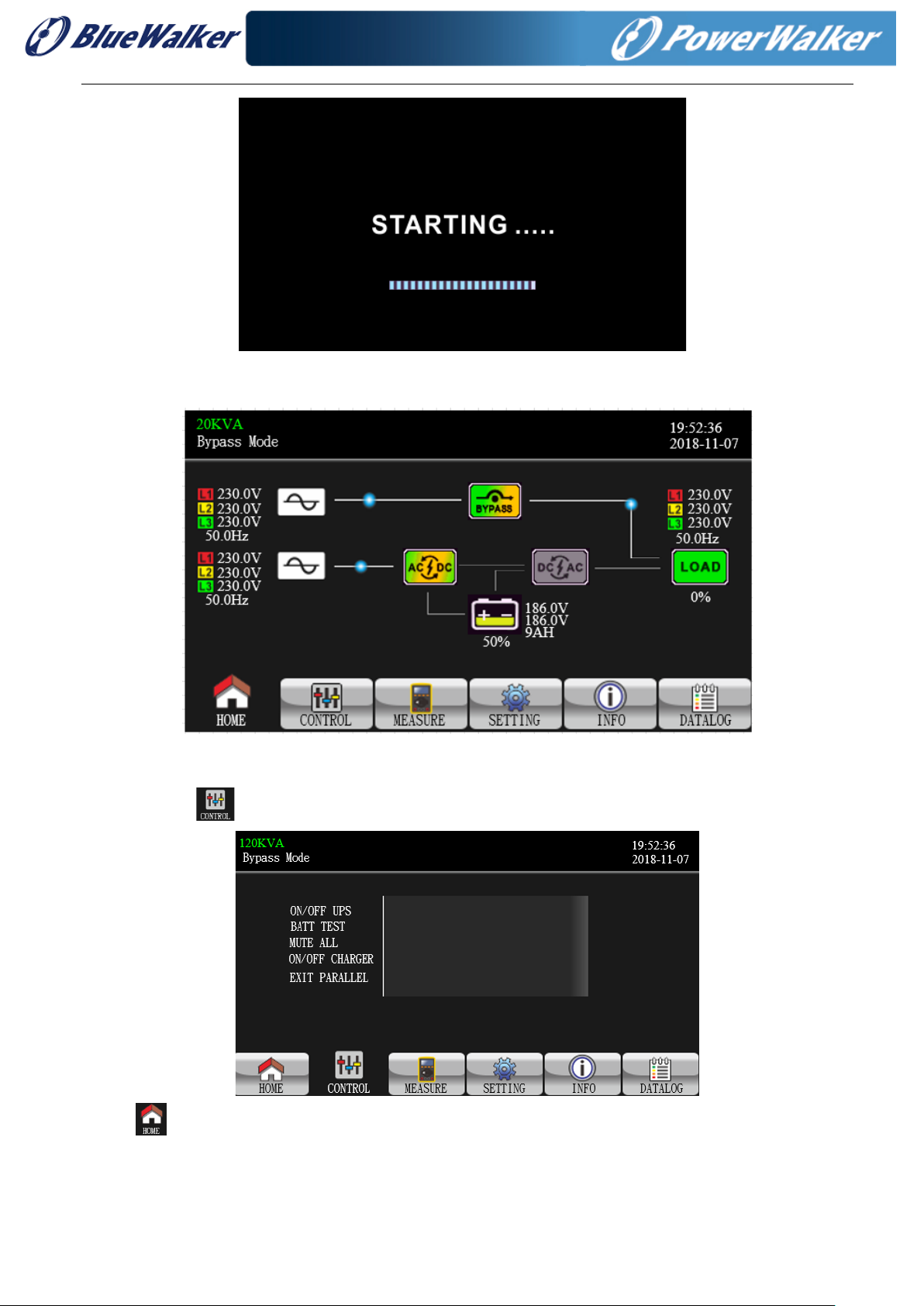
3-2-1 Main screen
Upon powering on, the LCD will start initialization approximately few seconds as shown below.
16
96 72.07
After initialization, the main screen will display as shown below. On the bottom, there are five icons to
represent five sub-menus: CONTROL, MEASURE, SETTING, INFO, DATALOG.
3-2-2 Control screen
Touch the icon to enter control sub-menu.
Touch icon to return back to main screen no matter it’s in any screen of any submenu.
This manual suits for next models
11
Table of contents
Other BlueWalker UPS manuals


