bmcm AMS42-LAN16fx User manual

AMS42-LAN16fx
5B Amplified Measurement System (LAN)
All-In-One Measurement System.
Compact. DAQ via LAN.
The AMS42-LAN16fx, a complete solution: ampli-
fier technology and data acquisition. A high-quality
network data acquisition system is already inte-
grated. Available in a robust aluminum housing as
a mobile tabletop unit with skid-proof, tip-up feet.
Modular Concept.
Equip Individually. Be Flexible.
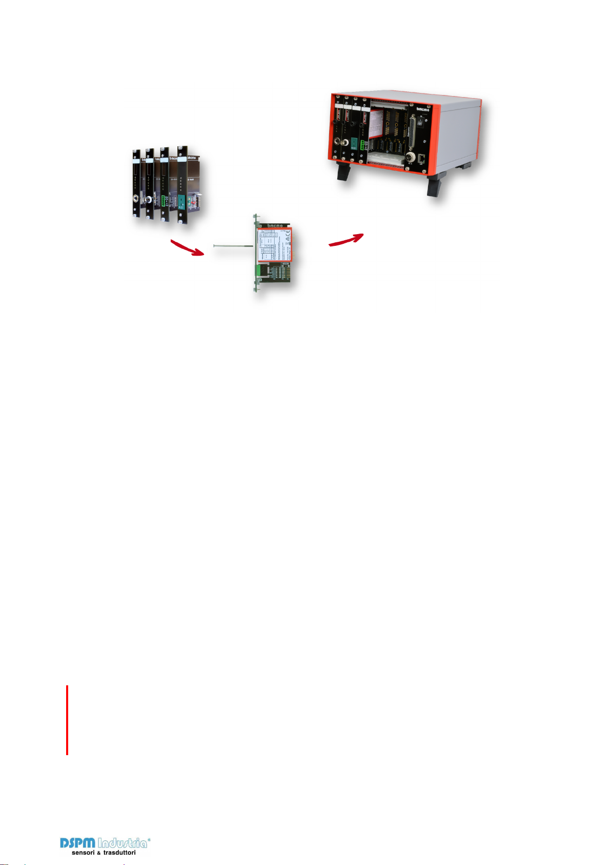
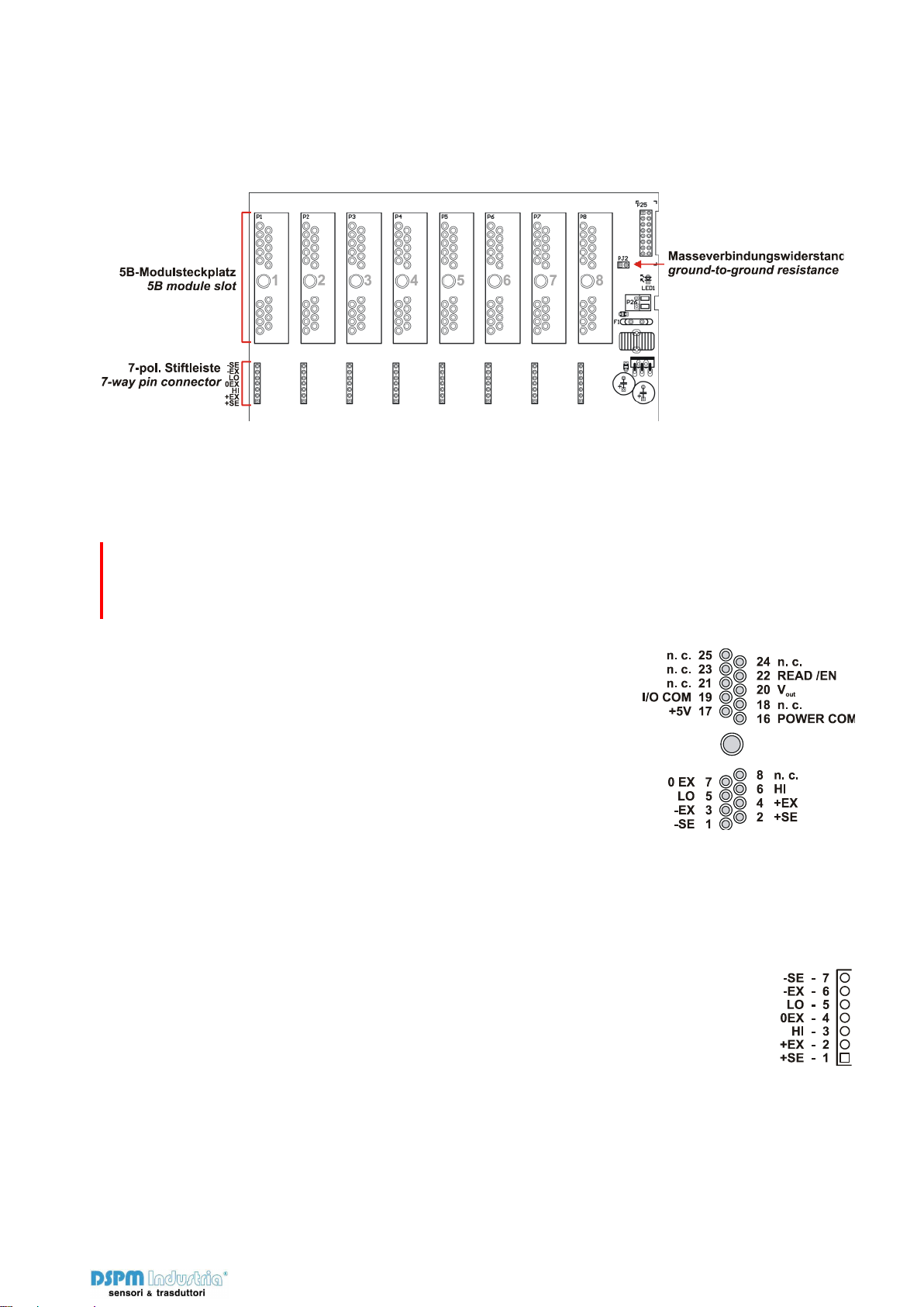
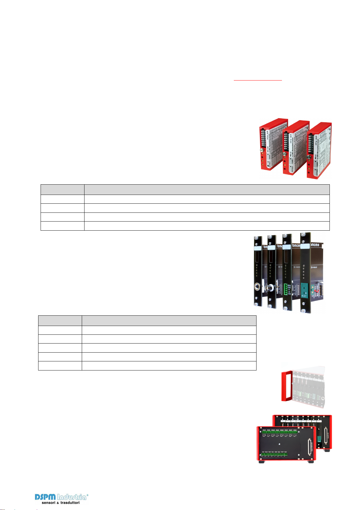
The AMS device is equipped with cassettes, on
which the required 5B measuring amplifiers are
mounted. The variety of available 5B modules al-
lows for the optimum adaptation of the
AMS42-LAN16fx to any special measuring task.
Choose Connector.
Mount 5B Amplifier. Done.
The available plug-in cassettes have different con-
nectors at the front panel. The suitable cassette
can be chosen depending on the sensor or signal
to be connected. Now the 5B module only has to
be fixed on the cassette and be integrated in the
AMS system.
Clearly Safe.
The galvanic isolation provided by the 5B modules
allows interference-free operation and protects
DAQ system and PC against high potentials.
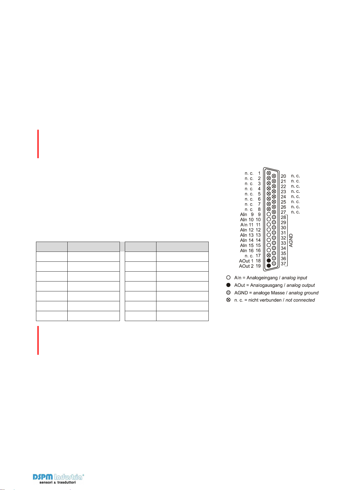
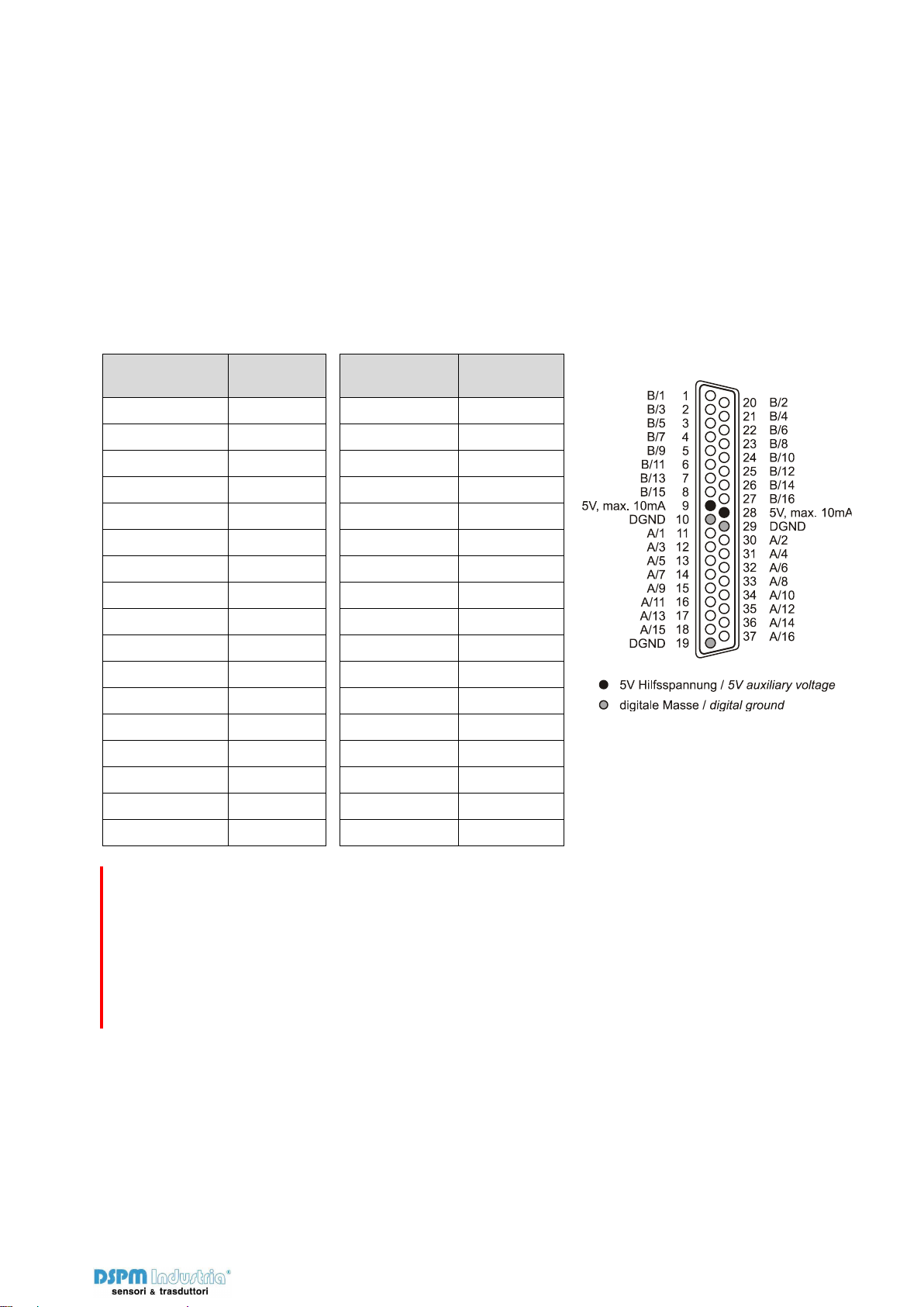
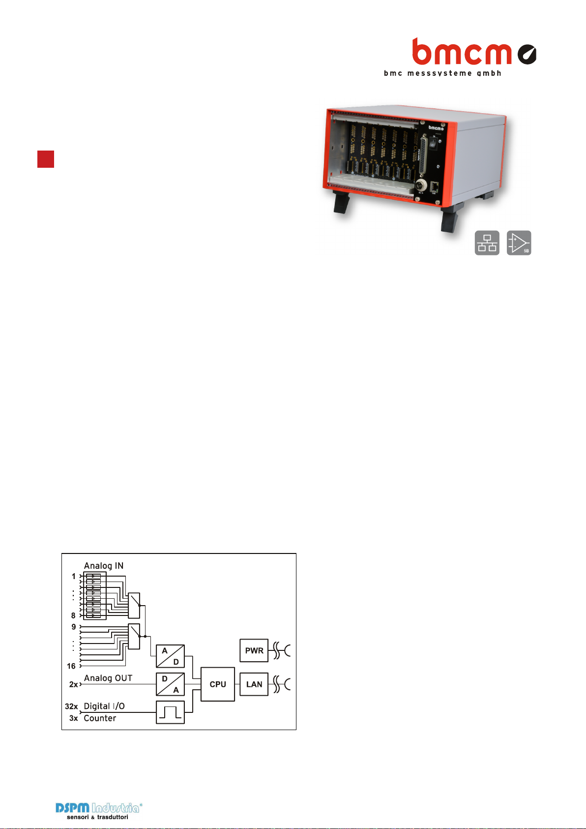
16 Analog IN. 2 Analog OUT.
Signals are connected at 8 amplifier inputs with 16
bit resolution and 250kHz total sampling rate. Ad-
ditional 8 analog inputs and 2 analog outputs are
available directly and without amplification at a D-
Sub 37 female.
32 Digital I/O. 3 Counters.
Digital states are recorded or set at 16 digital in-
puts and outputs each. The direction of the two
16-bit ports is set via software. Pulses, frequency,
position, and pulse time can be measured with
three 32-bit counters.
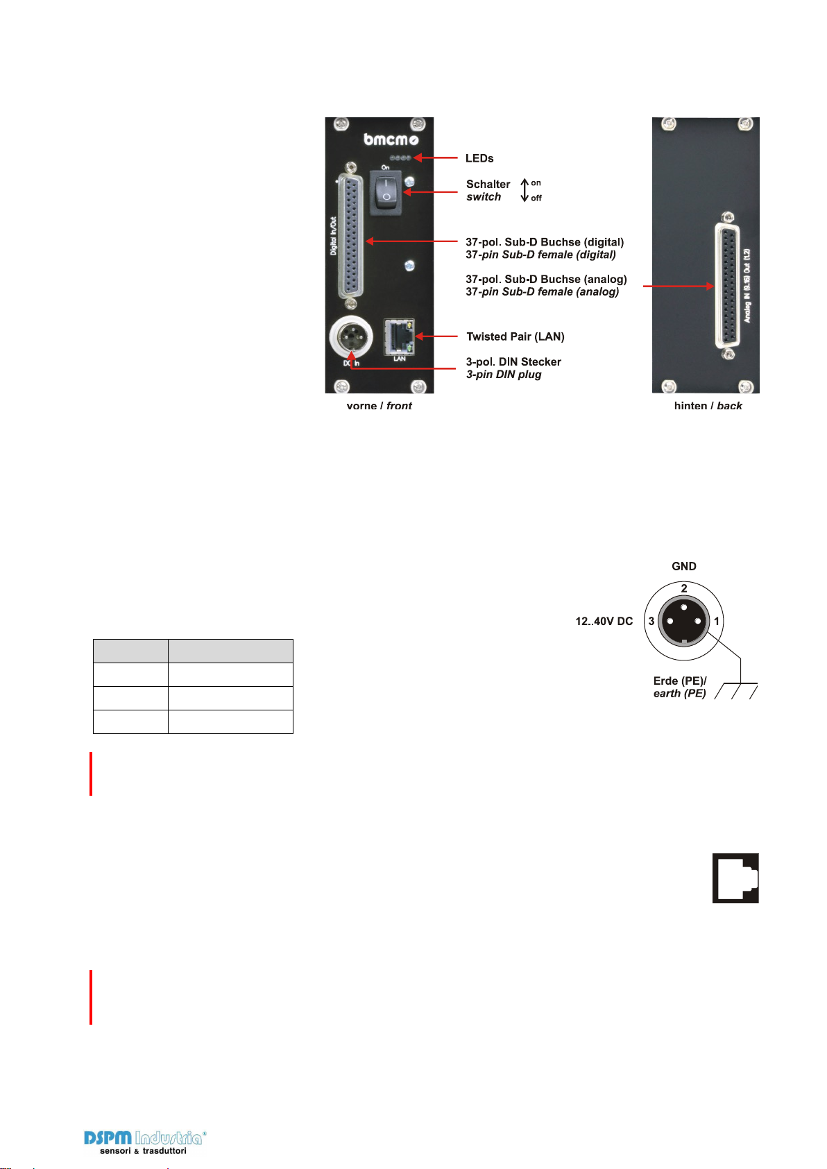
Networked. Distributed. Remote.
Synchronized, if you Like.
The LAN technology of the AMS42-LAN16fx allows
for measurement applications across great dis-
tances. Data are transmitted via network from arbi-
trarily many measuring points to a server PC. Sig-
nals of several devices can be synchronized with
each other. The TCP/IP protocol stands for reliable
data transmission – even via the internet.
Open for Everyone.
The amplifier measurement system is supported by
Windows®XP/7/8/10 as well as Mac OS X, Free
BSD, and Linux. The complete software for installa-
tion and programming of the AMS42-LAN16fx is
included. The device is supported by the DAQ and
analysis software NextView®.
Functional diagram
Via Paolo Uccello 4 - 20148 Milano

AMS42-LAN16fx
Seite 2
1 Start-up procedure
Before starting the device check the safe connection between the housing and earth.
All available software and documentation for the AMS42-LAN16fx are located on
www.bmcm.de/ams42-lan16fx-en in the tab
Downloads.
1. Step: Connect up
Set up a connection of a PC or measurement data server via network. The power
supply is enabled through the network (PoE), too. Alternatively the AMS42-LAN16fx
can be operated with an external power supply (s. Chap.
Fehler! Verweisquelle
konnte nicht gefunden werden.
). The device assigns itself a suitable link local IP ad-
dress when connected.
2. Step: Installation LAN-Admin
In order to check and change the network settings, firmware version and connection
quality of the AMS42-LAN16fx, the LAN-admin needs to be installed (s. Kap. 1.1). It
can be downloaded on www.bmcm.de/ams42-lan16fx-en in the tab
Downloads
in
the category
LAN-Admin – Configuration Software
.
3a Step: Measuring with NextView
To be able to use your measurement system with NextView, you just need to down-
load and install the latest version of NextView on www.nextview.de/download. In
case you did not buy NextView, request a free of charge trial version when first start-
ing NextView. Find more information about NextView and its installation on
www.nextview.de or in the manual on www.bmcm.de/man-nextview.
3b. Step: Measuring with API
In case you want to use the measurement device without NextView, you need to
download and install the free of charge programming interface LIBAD4. You can find
this on www.bmcm.de/ams42-lan16fx-en in the tab
Downloads
in the category
LI-
BAD – Programming Interface (API)
, too. Find more information on www.bmcm.de/li-
bad-en or directly in the manual www.bmcm.de/man-libad.
Via Paolo Uccello 4 - 20148 Milano

AMS42-LAN16fx
Seite 3
1.1 Configuration with LAN administration utility
The AMS42-LAN16fx is displayed by the software under the name "LAN-Base". The usage of the configuration software
is described in detail in the user’s manual UM-LAN-ADMIN.
1.1.1 Operation
In the left window of the program screen, all DAQ
systems with a working network connection to the
PC are listed displaying their serial number. The
AMS42-LAN16fx is displayed as "LAN-Base".
In the condition as supplied to the customer, the
device automatically self-assigns an IP address.
Select a network DAQ system to show the pa-
rameters of this device in the TABs on the right.
Settings can be modified by clicking the "Options"
button.
We strongly recommend using the automatically assigned configuration. Manual changes should only be done by a
network administrator.
1.1.2 Notes about TCP/IP
Each participant of the network has his own IP address consisting of four groups of numbers. To
guarantee that a data package arrives at the correct address, this IP address must have been given
out only once.
Each IP address contains the network number identifying the net your PC belongs to. Please make
sure the PC and the AMS42-LAN16fx are in the same net, i.e. they have the same network number,
to be able to communicate with each other.
1.1.3 Example Configuration for the Manual Input of the Network Settings
If there is only the PC and the DAQ system in your network (network
number 192.168.32.0), you can use the following configuration. The
IP address currently set in the PC is shown in the title bar of the
AMS42-LAN16fx Administration Utility:
Configuration
Value
IP-Address PC
192.168.32.1
IP-Address LAN-AD16fx
192.168.32.2
Network mask
255.255.255.0
1.2 Synchronisation
In NextView®, AMS42-LAN16fx devices can do measurement time-
synchronously in relation to real-time. The frequency of the sample clock is adjusted by means of a
configured NTP server.
Settings for time-synchronous measurements are done in the AMS42-LAN16fx Administration Utility
as well as in NextView®and are described in the user manual UM-LAN-ADMIN.
Via Paolo Uccello 4 - 20148 Milano

AMS42-LAN16fx
Seite 4
2 Installation
2.1 Assembly
a) Equip the AMS42-LAN16fx with the plug-in cassettes (see chapter 6.2) carrying the required
5B modules.
b) Carefully push the cassette along the guide bars of the relevant slot until the 7-way pin
connector of the cassette and the pins of the 5B module are plugged into the corresponding
connectors on the AMS backplane.
c) If using the option AMS-EXT8 for the AMS42-LAN16fx (see chapter 6.4), the additional cas-
settes 9..16 are mounted at the back of the device.
d) For a tight installation, fix the front panel at both ends with screws to the housing. Bridge un-
needed slots by a blank panel (AMS-K-BLANK) to protect the device against outside in-
fluences.
2.2 Software Installation and Start-up Procedure
a) Connect an external power unit to the 3-pin DIN coupling for 12-40V power supply (use a
supply cable with a cross sectional area >1mm2) and turn on the AMS42-LAN16fx by pressing
the switch to "1" (ON) (see chapter 3.1).
b) Connect the AMS device to the network (LAN) which is intended to communicate with a PC or
data acquisition server (see chapter 3.4).
c) If necessary, further software components to be used with the device can be installed now, as
described in chapter 1.
d) Eight analog input signals can be connected at the specific connector of the respective AMS
cassette panel. The other analog channels as well as digital lines are available directly and wit-
hout amplification at 37-pin D-Sub female connectors (see chapter 3.5 and 3.6).
•To change the cassettes, the power of the AMS device must be turned off!
•If the AMS system is operated standalone, additional grounding to enhance shielding is recommended but not man-
datory.
Via Paolo Uccello 4 - 20148 Milano

AMS42-LAN16fx
Seite 5
3 Connections and Assignments
All available connectors and
operating elements of the
AMS42-LAN16fx are acces-
sible on the right-hand side of
the device front and back.
3.1 Switch
The AMS42-LAN16fx is tur-
ned on (press "1") and off
(press "0") with the switch at
the front side.
3.2 LEDs
The four LEDs indicate the supply of the LAN measuring system and the integrated DAQ module
(supplied by the PC with 5V), or signalize when commands are sent to the PC.
3.3 Power Supply
The AMS device is supplied with power (12..40V) via the 3-pin DIN
plug. A power supply unit ZU-PW40W (24V, 1.67A DC) is optionally
available.
Pin
Assignment
1
n. c.
2
ground (GND)
3
12-40V DC
Connect the shield of the power supply with earth (PE).
3.4 Network
The PC/data acquisition server and the AMS42-LAN16fx communicate via LAN realized
with a Twisted Pair connection (RJ45, 100Mbit). Due to automatic MDI/MDIX, using a
crossover cable is not necessary. A Twisted Pair cable is available as accessory (ZUKA-
TP).
If the two LEDs in the LAN connector are flashing, data are transmitted.
Firewall software installed on the PC might interfere with the operation of the AMS42-LAN16fx. In this case, please
contact your network administrator.
Via Paolo Uccello 4 - 20148 Milano

AMS42-LAN16fx
Seite 6
3.5 Analog Channels
3.5.1 Measuring Amplifier Inputs
Eight analog signals can be connected to the amplifier inputs available at the respective connectors of
the cassette panels. Their assignment is illustrated in the data sheet of the AMS-K cassettes (see
chapter 6.2).
Additional 8 amplifiers inputs can be added with the option AMS-EXT8 (see chapter 6.4) at the back
of the device.
Depending on the application, the shield of the analog input cables can be applied to ground or 0V.
Be sure to connect at one end of the cable only. Run the signal ground separately if possible. Lay in-
put cable separately if possible.
Measurements can be effected on various potentials. The potential deviations, however, should not exceed 60V DC (ac-
cording to VDE Association of German Electrical Engineers).
3.5.2 Analog Outputs and Other Analog Inputs
The 37-pin D-Sub female connector at the back of the device
is designed for the direct and non-amplified connection of the
remaining analog inputs 9..16 and the analog outputs 1+2.
The input range (±10V, ±5V, ±2V, ±1V) is set via software (e.g.
in
NextView®
), the output range is ±10V, the resolution is 16
bit respectively.
The max. potentials to ground must not exceed
±
12V. Any channel overload may influence measurements of other chan-
nels and may lead to wrong values.
Pin
Assignment
Pin
Assignment
1..8
n. c.
15
AIn 15
9
AIn 9
16
AIn 16
10
AIn 10
17
n. c.
11
AIn 11
18
AOut 1
12
AIn 12
19
AOut 2
13
AIn 13
20..27
n. c.
14
AIn 14
28..37
AGND
Via Paolo Uccello 4 - 20148 Milano

AMS42-LAN16fx
Seite 7
3.6 Digital Channels and Counters
The AMS42-LAN16fx features two digital ports with 16 inputs or outputs each. The lines are bidirecti-
onal and set in groups of eight. Additionally integrated are three counters (quadrature decoders) for
pulse, frequency, position, or pulse time measurement.
With the option AMS-DIG8 (see chapter 6.4), 8 inputs and outputs each can be used as galvanically
isolated optocoupler inputs and relay outputs available at the back of the device.
3.6.1 Digital Assignment
All lines are led to the 37-pin D-Sub female connector at the device front. The pin assignment is as
follows:
D-Sub 37
(Digital In/Out)
Assignment
(Port/Bit)
D-Sub 37
(Digital In/Out)
Assignment
(Port/Bit)
11
A/1
1
B/1
30
A/2
20
B/2
12
A/3
2
B/3
31
A/4
21
B/4
13
A/5
3
B/5
32
A/6
22
B/6
14
A/7
4
B/7
33
A/8
23
B/8
15
A/9
5
B/9
34
A/10
24
B/10
16
A/11
6
B/11
35
A/12
25
B/12
17
A/13
7
B/13
36
A/14
26
B/14
18
A/15
8
B/15
37
A/16
27
B/16
10, 19, 29
DGND
9, 28
5V, max. 10mA
•The digital inputs and outputs are protected by serial resistors. Input voltages beyond the permitted voltage range of
0V..5V can damage the device.
•By default, port A is set to input, port B to output.
•Digital inputs are always read synchronously in time together with the analog inputs.
•Make sure the digital outputs of the device do not drive against the outputs of your signals.
3.6.2 5V Auxiliary Voltage
The AMS42-LAN16fx provides an auxiliary voltage (e.g. for sensor supply) at pin 9, 28 of the D-Sub37
female. The 5V DC output (max. 10mA) is protected by a fuse (multifuse). In case of overload, it is suf-
ficient to interrupt the power supply (turn off PC or disconnect the consumer load). After app. 1 min.,
the multifuse will be regenerated.
Via Paolo Uccello 4 - 20148 Milano

AMS42-LAN16fx
Seite 8
3.6.3 Counters with Pulse Time Measurement
The AMS42-LAN16fx features three 32-bit counters allowing the connection of incremental encoders.
The counter inputs (A, B, and Reset) can be assigned to any digital lines of the two digital ports (confi-
gure by software).
The AMS42-LAN16fx counts the number of incoming pulses (max. 16MHz) sampled at the connec-
tion of signal A. If the maximum counting range is reached, the counter will be reset to the minimum
value of the counting range. If the external counter reset is connected, the counter can be reset at any
time.
In comparison to a counter, the quadrature decoder used to connect an incremental encoder consi-
ders the counting direction by decoding a second phase-shifted signal.
To activate the counting function, the respective digital lines of the AMS42-LAN16fx must be assigned
to the counter via software.
Function
Description
max. Pulse Frequ.
Connection
Dig. Pins Used
Counting Range
Counter
Count á
16MHz
Signal A
1
0..232-1
Up/Down-counter
Count áâ
16MHz
Signal A, Signal B
2
-231 .. 231-1
Inkremental
encoder
Count áâ
16MHz
Signal A, Signal B
2
-231 .. 231-1
Pulse time
measurement
measure time
betw. 2 edges
temporal
resolution
16,67ns
16MHz
Signal A
1
0 - 71,58s
Please refer to the relevant documentation of your product for further information about connecting your incremental
encoder.
Via Paolo Uccello 4 - 20148 Milano

AMS42-LAN16fx
Seite 9
4 AMS Backplane
The AMS-backplane provides 8 slots for 5B modules and the AMS-K plug-in cassettes (see chapter
6.2) carrying the 5B modules. If the AMS42-LAN16fx is used with the optional add-on AMS-EXT8 (see
chapter 6.4), eight slots each are available at the front and at the back of the device.
4.1 Ground-to-Ground Resistance
Ideally, the output ground is not electrically connected with the power supply ground. If, however, a
connection to ground is necessary (e.g. to use the output switch in the 5B module), the 2-pin jumper
(see fig. above) must be closed.
In the case of electrically connected systems (e.g. PC), this jumper represents a high-resistance bridge (1k
W
) and may
generate a hum loop!
4.2 Module Pin Assignment
The pin assignment on the right shows the top view of the module
backplane (see chapter 4).
The pin assignment corresponds to the 5B modules of Analog De-
vices®, BURR BROWN®etc. However, an additional 0EX pin has
been introduced, which is particularly suitable for ungrounded shiel-
ding. This is a specific assignment of BMC Messsysteme GmbH.
This pin is not connected in modules of other manufacturers.
4.3 Fuse
The fusing of the AMS backplane (see chapter 4) is effected on the backplane with one reversible
semi-conductor fuse. In case of overload it turns off. To make the fuse work effectively again, first re-
move the cause for overload before disconnecting the power supply of the AMS42-LAN16fx.
4.4 Connection for AMS Cassettes
The cassettes are connected to the AMS backplane (see chapter 4) via 7-way pin
connectors leading the input signals connected at the cassette panel to the backplane.
The assignment of the 7-way female connector on the board is illustrated in the figure
on the right-hand side.
Via Paolo Uccello 4 - 20148 Milano

AMS42-LAN16fx
Seite 10
5 Synchronization
In NextView®, AMS42-LAN16fx devices can do measurement time-synchronously in relation to real-
time. The frequency of the sample clock is adjusted by means of a configured NTP server. Settings
for time-synchronous measurements are done in the AMS42-LAN16f Administration Utility (see chap-
ter 1.1) as well as in NextView and are described in the user manual UM-LAN-ADMIN.
6 Supplementary Products for the AMS42-LAN16fx
6.1 5B Modules (MA Line)
The 5B measuring amplifiers from bmcm allow for the professional sig-
nal adjustment to a data acquisition system.
The amplifier output is ±5V or 0..5V. Most of the modules are electri-
cally isolating and provide sensor supply.
The following 5B modules from bmcm are available:
Product
Description
MA-UNI
universal amplifier with galvanic isolation for U, I, R, thermocouple, strain gauge, LVDT
MA-UI
multi-range amplifier with galvanic isolation for U, I
MA-U
voltage measuring amplifier with galvanic isolation, 50kHz bandwidth
MA-P09/12/15
power supply modules ±9V/ ±12V/±15V
6.2 Plug-in Cassettes (AMS-K Line)
The amplifier system can individually be equipped with 8 plug-in cas-
settes (or 16 with option AMS-EXT8, see chapter 0).
Each cassette is equipped with the relevant 5B module and suitable
input connector.
The suitable input connector on the front panel guarantees for the re-
levant connection to be available when exchanging the cassette.
The following cassettes are available:
6.3 AMS-HANDLE2
For mobile use, the AMS42-LAN16fx can be equipped with two stable me-
tal handles at the housing frame (AMS-HANDLE2).
6.4 AMS-EXT8, AMS-DIG8
With the add-on option AMS-EXT8, the analog inputs 9..16 are
available as amplifier inputs, and eight opto-isolated digital inputs and
eight relay outputs with the option AMS-DIG8.
Product
Description
AMS-K-BIN5
cassette with panel and 5-pin Binder female connector (712 series)
AMS-K-BLANK
blank panel
AMS-K-BNC
cassette with front panel and BNC female connector
AMS-K-CO5
cassette with front panel and 5-pin terminal connector
AMS-K-THK
cassette with front panel and thermocouple socket (type K)
Via Paolo Uccello 4 - 20148 Milano

AMS42-LAN16fx
Seite 11
These channels are accessible at the back of the amplifier measurement system and not at the 37-pin
D-Sub females of the device anymore (see chapter 3.5.2 and 3.6.1).
7Important Notes for Using the AMS42-LAN16fx
•The device is only suitable for extra-low voltages - please observe the relevant regulations! Only
use the device with housing closed. ESD voltages at open lines may cause malfunction.
•Only use an electrical isolated power supply unit (with CE).
•For cleaning only use non-solvent detergents. The product is designed to be maintenance-free.
•For calibration purposes, the device must be returned to BMC Messsysteme GmbH.
•For reasons relating to CE use shielded cables. Connect the shield to ground at one end only.
Close open inputs if possible. ESD voltages on lines may cause malfunction during operation.
•When mounting the cassettes, a connection between power supply ground and chassis of the
device is made via the module screw.
•The Gain is adjusted to even values. Therefore only 64000 (with 16 bit) values of the full range of
the converter are used. As a result, the measuring ranges are effectively slightly larger (e.g. ±5.12V)
than the indicated measuring ranges, providing for the advantage that overranges can be recog-
nized.
•The device must not be used for safety-relevant tasks. With the use of the product, the customer
becomes manufacturer by law and is therefore fully responsible for the proper installation and use
of the product. In the case of improper use and/or unauthorized interference, our warranty ceases
and any warranty claim is excluded.
Do not dispose of the product in the domestic waste or at any waste collection places. It has to be
either duly disposed according to the WEEE directive or can be returned to bmcm at your own
expense.
Via Paolo Uccello 4 - 20148 Milano

AMS42-LAN16fx
Seite 12
8 Technical Data (typical at 20°C, after 5min., +24V supply)
•Analog Channels
Inputs (Measuring range):
8 amplifier inputs (±5V), 8 single-ended, non-amplified inputs (±10V, ±5V, ±2V, ±1V)
Measuring range // Noise:
±10V // ±5 LSB
±5V // ±7 LSB
±2V // ±8 LSB
±1V // ±8 LSB
Sampling rate // Resolution:
max. 250kHz total sampling rate* // 16 bit
Abs. accuracy // Memory depth:
±2.5mV // only depending on the size of the hard disk of the server PC
Surge protection:
±35V (when turned on), ±20V (when turned off), max. ±20mA in total of all input channels!
Input resistance // Input capacity:
1MW(with PC turned off: 1kW) // 5pF
Zero shift // Gain drop:
±50ppm/C // ±50ppm/C
Frequency accuracy // Frequency drift:
max. ±100ppm // max. ±50ppm/C
Outputs // Output range // Output cur-
rent:
2 voltage outputs (16 bit) // ±10V // max. 1mA
Galv. isolation (to PC // to each other):
all analog channels electrically isolated to the PC // amplifier inputs: depends on the 5B modules used
* The total sampling rate is the sum of the sampling rates of the individual used channels (e.g. if 5 channels are scanned with 1kHz, the total sampling
rate adds up to 5kHz).
The values for accuracy always relate to the respective measuring range. Errors might add at worst.
•Digital Channels
Channels // Level:
16 Digital IN, 16 Digital OUT // CMOS/TTL compatible (low: 0V..0.7V; high: 3V..5V)
Counter:
19-bit counter, up/down counter or incremental encoder; connect at digital pins
Resistance Ri // Output current:
Digital IN: 10kW, Digital OUT: 1kW// 0.5mA
•General Data
Power supply:
+12..40V DC, ±5%, min 3W, max. 20W (depends on number of 5B modules used) at 3-pin DIN plug
Analog connections:
amplifier inputs: different connectors (Phoenix, Binder, BNC, Thermo) on the front panels
of the cassettes; other analog channels at a 37-pin D-Sub female at the device back
Digital connections:
all channels at a 37-pin D-Sub female at the device front
LAN connection:
Twisted Pair RJ45 connector, 100Mbit
CE standards:
EN61000-6-1,EN61000-6-3,EN61010-1;for decl. of conformity (PDF)
ElektroG // ear registration:
RoHS and WEEE compliant // WEEE Reg.-No. DE75472248
Max. permissible potentials // Protection:
60V DC acc. to VDE
, max. 1kV ESD on open lines // IP20
Temperature ranges // Relative humidity:
operating temp. -25..50C, storage temp. -25..70C // 0-90% (not condensing)
Dimensions (W x H x D):
23,5cm x 13,2cm x 25,6cm
Delivery:
device
Available accessories:
plug-in cassettes with front panels and different connectors of the AMS-K series,
8-channel extension AMS-EXT8 for add. 8 amplifier inputs, extension AMS-DIG8 for 8 optocoupler inputs and
8 relay outputs, D-Sub plug ZU37ST, 3-pin DIN socket ZU3DIN, gender changer ZU37SS, connecting cables
ZUKA37SB/SS (D-Sub), ZUKA-TP (Twisted Pair), desktop power supply
ZU-PW40W (24V, 1.67A DC), carrying handle AMS-HANDLE2
Warranty:
2 years from date of purchase at bmcm, claims for damages resulting from improper use excluded
•Software
Software free of charge download:
LIBAD4 SDK for C/C++ programming on Windows® XP/7/8/10, Mac OS X, FreeBSD, Linux; trial version of
measuring software NextView®for hardware test & operation; config. software LAN-Admin
NextView®(optional):
professional software (versions: Professional, Lite) for the acquisition and analysis of measurement data on
Windows®8/10
Manufacturer: BMC Messsysteme GmbH. Subject to change due to technical improvements. Errors and printing errors excepted. Rev. 4.3
02/05/2020
Via Paolo Uccello 4 - 20148 Milano
Table of contents
Other bmcm Measuring Instrument manuals
Popular Measuring Instrument manuals by other brands

Black Box
Black Box FOLTIB manual

Accu-Flo Meter Service Ltd.
Accu-Flo Meter Service Ltd. TM Series owner's manual

FRONIUS
FRONIUS Datamanager 2.0 operating instructions

HIK VISION
HIK VISION DS-MP1803 user manual

MICRO-POWER
MICRO-POWER Acess BMU Series Instructions for use

vanEssen
vanEssen TD-Diver DI8 Series product manual