BMS DLC50 User manual

DLC50 DOWNLINK CONTROL PANEL
Installation/Operation Manual
Doc. No. 6051439500 Rev. A
The document reference is online, please check the correspondence between the online documentation and the printed version.

Broadcast Microwave Services, Inc. ▪12367 Crosthwaite Circle, Dock 10 ▪Poway, CA 92064 ▪USA
Tel: +1 (858) 391-3050 ▪Toll-free (US): 800-669-9667 ▪Fax: +1 (858) 391-3049 ▪support@bms-inc.com ▪www.bms-inc.com
Broadcast Microwave Services Europe GmbH ▪Schwalbacher Str. 12 ▪65321 Heidenrod Germany
Tel: +49-6124-72 39-00 ▪Fax: +49-6124-72 39-29
©2010 Broadcast Microwave Services. All rights reserved.
This document and the information contained in it is the property of Broadcast Microwaves Services, Inc. and may be the subject
of patents pending and granted. It must not be used for commercial purposes nor copied, disclosed, reproduced, stored in a
retrieval system or transmitted in any form or by any means (electronic, mechanical, photocopying, recording or otherwise),
whether in whole or in part, without BMS prior written agreement.
The document reference is online, please check the correspondence between the online documentation and the printed version.

DLC50 Control Panel Installation and Operation Manual | Doc. No. 6051439500 Rev. A
Broadcast Microwave Services I
Document Revision History
Initial release July 2010 Rev. -
Added instructions on loading channel plan via the USB drive; clarified
instruction on location of USB files August 2010 Rev. A
Conventions Used in This Manual
NOTE: Notes provide supplementary information. They are highlighted for emphasis, as in this
example, and are placed immediately after the relevant text.
CAUTION: Cautions give information which, if strictly followed, will prevent damage to equipment
or other goods. They are boxed for emphasis, as in this example, and are placed immediately
preceding the point at which the reader requires them.
WARNING: Warnings give information which, if strictly observed, will prevent personal injury or
death, or damage to personal property or the environment. They are boxed and shaded for
emphasis, as in this example, and are placed immediately preceding the point at which the reader
requires them.
ATTENTION!
DO NOT use right-angle connectors or adapters on the RF Power Out cable assemblies. Right-
angle connectors may have significant RF power loss at the operating frequencies of this system.
FOR ALL BMS TRANSMITTERS – Operation of a BMS transmitter product generally requires a
license. It is the responsibility of the user to obtain all required operating licenses.
ONLY FOR PRODUCTS AWAITING FCC CERTIFICATION – This device has not been authorized as
required by the rules of the US Federal Communications Commission. This device is not, and may
not be, offered for sale or lease, or sold or leased, in the US until authorization is obtained.
Acceptance Test Procedure (ATP) test data results by product serial number are typically shipped
with all units and indicate the equipment to be operating within advertised specifications. Contact
BMS to request this data.
Read and Follow Instructions! All safety and operating instructions should be read before this
product is operated. All operating and use instructions should be followed. This manual should be
retained for future reference.
EMC Compliance – This equipment is certified to the EMC requirements detailed in the technical
specifications. To maintain this certification, only use the cables supplied or if in doubt contact
BMS Customer Service.
RF Exposure Information – For body worn operation, the device has been tested and meets FCC
RF exposure guidelines when used with an accessory that contains no metal and that positions
device a minimum of 7.9” (20 cm) from the body. Use of other accessories may not ensure
compliance with FCC RF exposure guidelines.
Compliance – This device complies with several standards. Please refer to the chapter,
Specifications, in this manual for a complete list of standards.
The document reference is online, please check the correspondence between the online documentation and the printed version.

DLC50 Control Panel Installation and Operation Manual | Doc. No. 6051439500 Rev. A
Broadcast Microwave Services II
Registered and General Trademarks
Best endeavours have been made to acknowledge registered trademarks and trademarks used
throughout this Reference Guide. Any notified omissions will be rectified in the next issue of this
Reference Guide. Some trademarks may be registered in some countries, but not in others.
Registered trademarks and trademarks used are acknowledged below and marked with their
respective symbols. They are not referenced within the text of this Reference Guide.
•Ethernet® is a registered trademark of Xerox Corporation.
•XILINX® is a registered trademark of Xilinx Inc.
•Pozidriv™ is a trademark of European Industrial Services.
•Windows NT®, Windows XP, Windows 7 are registered trademarks of Microsoft Corporation.
•NDS™ is a trademark of NDS Limited.
About This Manual
This product manual provides instructions and information on the installation and operation of the
indicated BMS product.
The manual should be stored in a safe place and remain readily available during the operational
lifetime of the unit. It is not intended for this manual to be revised by issuing and replacing individual
pages. Any revision will be done by a complete reissue. Additional copies of this manual can be
ordered from BMS. The equipment should only be passed on to a third party together with the relevant
documentation. For further information please visit our website at www.bms-inc.com.
The document reference is online, please check the correspondence between the online documentation and the printed version.

DLC50 Control Panel Installation and Operation Manual | Doc. No. 6051439500 Rev. A
Broadcast Microwave Services III
Contents
1INTRODUCTION ..............................................................................................................................................1
1.1 Transmitter Serial Port (COM2)................................................................................................................4
1.2 Receiver Serial Port (COM3)....................................................................................................................4
1.3 Remote Serial Port (COM0) .....................................................................................................................4
2INSTALLATION................................................................................................................................................5
2.1 Installing the DLC50 (replacing an HCP50-II)...........................................................................................5
2.2 Installing the DLC50 (new installation) .....................................................................................................5
2.3 Connectors and Pin-outs..........................................................................................................................9
2.3.1 Power Cable Connector............................................................................................................................................9
2.3.2 DB25-5 Connector.....................................................................................................................................................9
2.3.3 TAA-101 Cable Connector Pin-out..........................................................................................................................10
2.4 DC Power and DC Power Control Connections .....................................................................................10
2.5 Transmitter Connections ........................................................................................................................10
2.6 RF Power Amplifier Connections............................................................................................................11
2.7 Receiver Connections ............................................................................................................................11
2.8 Remote Connections..............................................................................................................................11
2.9 Actuator Connections.............................................................................................................................12
2.10 Relay Connections .................................................................................................................................12
2.11 External Dimmer Connections................................................................................................................13
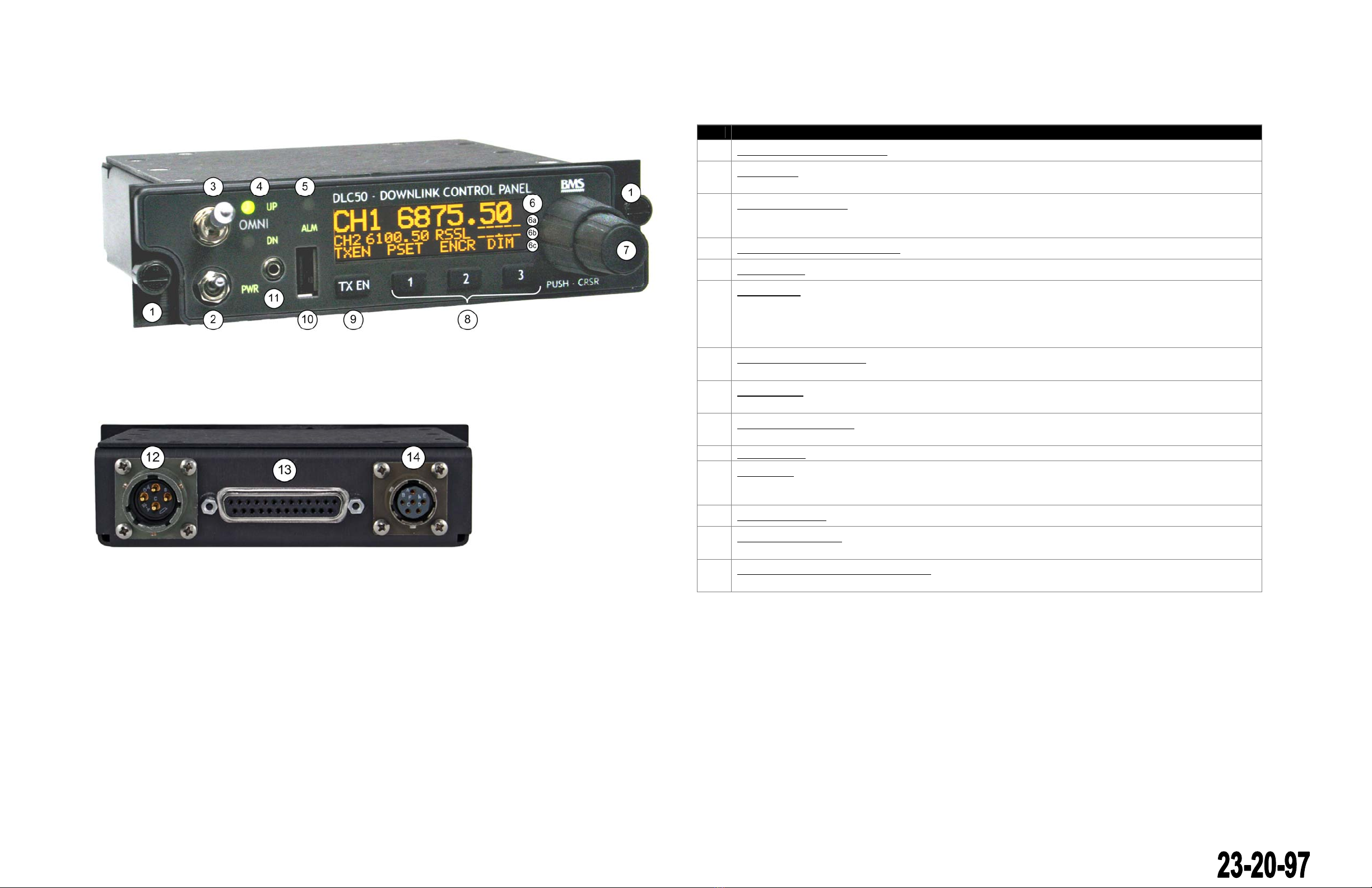
3DISPLAYS, CONTROLS AND MENU NAVIGATION ....................................................................................14
3.1 Display and LEDs...................................................................................................................................14
3.2 Keypad...................................................................................................................................................15
3.3 Rotary encoder.......................................................................................................................................15
3.4 Menu Navigation ....................................................................................................................................16
4SETUP AND CONFIGURATION....................................................................................................................17
4.1 Language Setup.....................................................................................................................................17
4.2 RX Serial Setup......................................................................................................................................17
4.3 TX Serial Setup......................................................................................................................................17
4.4 Remote Serial Setup ..............................................................................................................................17
4.5 USB Flash Functions..............................................................................................................................18
4.5.1 Example: Loading a TX Channel Plan from a USB Thumb Drive...........................................................................19
4.6 External Relay Setup..............................................................................................................................19
4.7 Presets Setup.........................................................................................................................................20
4.8 Simple UI Setup .....................................................................................................................................20
4.9 Soft-Key Setup.......................................................................................................................................21
4.10 Key-timer Setup......................................................................................................................................21
4.11 System Functions...................................................................................................................................21
5OPERATION...................................................................................................................................................22
5.1 Selecting a TX or RX Channel................................................................................................................22
5.2 Selecting a TX or RX Frequency............................................................................................................22
5.3 Recalling a TX or RX Preset...................................................................................................................22
5.4 Recalling, Saving and Erasing a DLC50 Preset.....................................................................................22
5.5 Setting Encryption or Decryption............................................................................................................23
5.6 Setting RF Power Level..........................................................................................................................23
5.7 Changing the RX meter Type.................................................................................................................23
5.8 Dimming the Panel and Display .............................................................................................................23
6SPECIFICATIONS..........................................................................................................................................25
7PREVENTIVE MAINTENANCE......................................................................................................................27
8TROUBLESHOOTING ...................................................................................................................................28
9REPAIR SERVICE/WARRANTY INFORMATION..........................................................................................29
9.1 Customer Service Contact Information...................................................................................................30
10 GLOSSARY....................................................................................................................................................31
11 INDEX.............................................................................................................................................................33
The document reference is online, please check the correspondence between the online documentation and the printed version.

DLC50 Control Panel Installation and Operation Manual | Doc. No. 6051439500 Rev. A
Broadcast Microwave Services IV
12 APPENDIX......................................................................................................................................................34
List of Figures
Figure 1. DLC50 downlink control panel....................................................................................................................1
Figure 2. Generic DLC50 Microwave System............................................................................................................2
Figure 3. DLC50 Control Panel Components, front view ...........................................................................................3
Figure 4. DLC50 Control Panel components, rear view.............................................................................................3
Figure 5. Panel mounting dimensions recommended for the DLC50 (per MS25212C) .............................................5
Figure 6. DLC50 TO HCP50 harness (CCII/HCII) adapter (BMS# 7314395012).......................................................6
Figure 7. DLC50 to HCP50 harness (CTxx40ARINC) adapter (BMS# 7314395011) ................................................6
Figure 8. Basic connection diagram...........................................................................................................................7
Figure 9. Typical installation ......................................................................................................................................7
Figure 10. DLC50 chassis dimensions.......................................................................................................................8
Figure 11. DLC50 power connector...........................................................................................................................9
Figure 12. DB25-5 connector.....................................................................................................................................9
Figure 13. DLC50 to TAA-101 antenna actuator connector.....................................................................................10
Figure 14. Remote Primary to Secondary “null-modem” connection .......................................................................11
Figure 15. Front panel 2.5mm serial cable...............................................................................................................12
Figure 16. Normal Display .......................................................................................................................................14
Figure 17. Display showing TXEN status (transmitter on)........................................................................................14
Figure 18. Diplexer subband switching configuration example................................................................................20
Figure 19. Multiple subband filter array configuration example................................................................................20
Figure 20. BMS product label ..................................................................................................................................29
List of Tables
Table 1. DLC50 Models.............................................................................................................................................2
Table 2. DLC50 front and rear switches and ports descriptions.................................................................................3
Table 3. Power connector pin-out (PT02E-12-4P).....................................................................................................9
Table 4. DB25-S connector pin-out............................................................................................................................9
Table 5. TAA-101 control connector pin-out (PT02E-10-98S) .................................................................................10
The document reference is online, please check the correspondence between the online documentation and the printed version.

DLC50 Control Panel Installation and Operation Manual | Doc. No. 6051439500 Rev. A
Broadcast Microwave Services 1
1 INTRODUCTION
The DLC50 (Figure 1) is a control panel for airborne microwave systems in rotary or fixed-wing aircraft.
It is user configurable for a large range of equipment and capabilities and is software upgradable. While
the DLC50 is intended to functionally replace the HCP50-II, its capabilities extend far beyond those of
the HCP50-II.
Figure 1. DLC50 downlink control panel
The DLC50 can control a transmitter, a receiver, an antenna actuator, RF Power Amplifier, and several
external relays. See Figure 2. Control of transmitter and receiver are accomplished via dedicated or
shared serial ports (user selectable).
Remote control of DLC50 is possible by connecting another DLC50 via the remote control port. The
remote DLC50 and the primary DLC50 will have equal priority control of all functions except the
antenna actuator which remains dedicated to the primary DLC50. Alternately, the primary DLC50 may
be slaved to an external flight computer for remote control, or a laptop may be used for direct access to
the transmitter and/or receiver for transmitter/receiver maintenance.
Updates of the DLC50 firmware may be made via the front panel serial port, while updates to channel
plans, presets, preferences, etc. may be made via the front panel USB host port using a USB thumb
drive. Configurations, preferences, and channel plans may also be saved to a USB thumb drive
connected to the USB host port. A generic system diagram is shown below.
The document reference is online, please check the correspondence between the online documentation and the printed version.

DLC50 Control Panel Installation and Operation Manual | Doc. No. 6051439500 Rev. A
Broadcast Microwave Services 2
Figure 2. Generic DLC50 Microwave System
Use of a BMS Power Voltage Relay (PVR) to distribute power to the microwave equipment enables the
power switch on the DLC50 to control power to all attached devices. The PVR also provides a separate
switched power connection for an external Power Amplifier (PA).
The DLC50 is available in the models shown in Table 1. Any of these models may be used as a drop-in
replacement for HCP50-II controllers when used with adapter cable 7314395012.
Table 1. DLC50 Models
BMS P/N Model
Number Description
8714395000 DLC50-A
Downlink Control Panel with Antenna actuator switch. Drop-in replacement
for the HCP-50-II using accessory adaptor cable (sold separately).
8714395001 DLC50-AN
Downlink Control Panel with Antenna actuator switch and NVIS-B
compatibility. Drop-in replacement for the HCP-50-II using accessory
adaptor cable (sold separately).
8714395002 DLC50
Downlink Control Panel. Drop-in replacement for the HCP-50-II using
accessory adaptor cable (sold separately).
8714395003 DLC50-N
Downlink Control Panel with NVIS-B compatibility. Drop-in replacement for
the HCP-50-II using accessory adaptor cable (sold separately).
The DLC50 switches and ports are defined in Table 2.
The document reference is online, please check the correspondence between the online documentation and the printed version.

DLC50 Control Panel Installation and Operation Manual | Doc. No. 6051439500 Rev. A
Broadcast Microwave Services 3
Figure 3. DLC50 Control Panel Components, front view
Figure 4. DLC50 Control Panel components, rear view
Table 2. DLC50 front and rear switches and ports descriptions
Item Description
1 Panel Mounting Fasteners (Dzus) (x2)
2 Power Switch: Turns on the DLC50 control box and enables the external main system power relay, which in turn
supplies power to all of the RF equipment (transmitters and receivers).
3 Antenna Actuator Switch: Primary control of antenna actuator; when switched to the “up” position, the TAA-101
retracts the antenna. When switched to the “down” position, the TAA101 deploys the antenna. The switch contains a
“locked” position and must be pulled to switch.
4 Antenna Actuator Position Indicators: Green LED=Up, Amber1LED=Down
5 Alarm Indicator: Amber1 LED (dimmable) indicates fault condition.
6
OLED Display: Transmitter operating frequency and/or channel is displayed on the top line (6a) in double-size text.
The middle line (6b) displays receiver frequency and status. During menu navigation it displays the active menu
item. Other status may use the middle line while not navigating the menus. The bottom line (6c) labels the user-
defined soft-keys. During menu navigation, the bottom lines become navigation keys.The OLED display is yellow 2.
The display is dimmable.
7 Dual Rotary Encoder Control: A dual concentric rotary encoder with integrated push-button switch provides an
intuitive means of navigating menus and making selections.
8 Preset Buttons: Three momentary pushbutton switches that are user-definable soft-keys. The user selected function
is displayed on the bottom line of the text display (6c) above the key.
9 Transmitter Enable Button: A momentary pushbutton switch that toggles the RF enable command on and off. RF
status is displayed on the text display.
10 USB Drive Port: Accepts USB thumb drive for updating firmware, channel plans, configuration, and presets.
11 Remote Port: Front panel access to the remote port (RS-232) allows a PC to be connected for configuration of
attached transmitter or receiver, and other maintenance functions. This port is also available on the I/O Interface
connector of the rear panel. Permanent installation connections should use the rear-panel connection for this port..
12 Power In Connector: Power cable connection; see section 2.2 for details, pinouts.
13 I/O Interface Connector: Provides connections to various features such as dimming, Serial ports, and relay control;
see section 2.2 for details, pinouts.
14 TAA-101 Actuator Control Cable Connector: Connects control cable to TAA-101 antenna actuator; see section 2.2
for details, pinouts.
Note 1 - NVIS models use only class-B green LEDs
Note 2 - NVIS models use a blue display and filter
The document reference is online, please check the correspondence between the online documentation and the printed version.

The document reference is online, please check the correspondence between the online documentation and the printed version.

DLC50 Control Panel Installation and Operation Manual | Doc. No. 6051439500 Rev. A
Broadcast Microwave Services 4
1.1 Transmitter Serial Port (COM2)
The transmitter serial port COM2 is used to control the attached transmitter and monitor its status. The
serial port is setup in the configuration menu for the specific model of transmitter. The DLC50 will then
configure the serial port for the correct control format and data rate for the specified transmitter.
1.2 Receiver Serial Port (COM3)
Generally, the receiver will use serial port COM3. The receiver port is used to control the attached
receiver and monitor its status.The serial port is setup in the configuration menu for the specific model
of receiver. The DLC50 will then configure the serial port for the correct control format and data rate for
the specified receiver.
1.3 Remote Serial Port (COM0)
The Remote Serial Port (COM0) is a multifunction serial port that is accessible on both the rear panel
and the front panel. The specific function is user selectable via the menu system. The remote port is
disabled by default, but the following types of functions are supported: Remote Primary, Remote
Secondary, Remote Client Serial, Pass-thru (TX port), Pass-thru (RX port), and Programming. Each of
these modes is discussed below. Although the Remote Serial port is available on both the front panel
and the I/O connector on the rear panel, more permanent connections (such as remote client, remote
primary or remote secondary) should use the I/O connector on the rear panel. The front panel
connection is intended to be convenient and compact for occasional short-term connections (such as
TX pass-thru or RX pass-thru) during maintenance only.
The remote primary and remote secondary modes allow a second DLC50 (the secondary) to connect
to a DLC50 (the primary) that is installed in an aircraft. This allows the secondary DLC50 to act as a
secondary point of control for the microwave equipment. The secondary DLC50 mimics the primary
DLC50 providing identical displays and control of any attached transmitter and receiver. TAA-101
actuator control is reserved for the primary DLC only. On power-up, the secondary DLC50 will display
an initial “splash” screen, then a second “splash” screen will display “Remote Secondary Mode” “Press
any key to cancel”. A 10 second countdown will display. If a key is pressed during the 10 seconds, the
remote port will be changed to disabled and the DLC50 will enter “normal” mode. If no key is pressed
within the countdown, the DLC50 will enter Remote Secondary Mode and begin communications with
the primary DLC50. To cancel remote secondary mode, select none in the config:remote port menu.
“Remote Client Serial” mode uses the DLC50 variant of the WDTSII remote control protocol to control
specific functions on the DLC50 and any connected transmitter or receiver through a single serial port.
Commands are directed to either the transmitter, receiver, or DLC50 by use of selective addressing.
Commands directed at the transmitter should use the address A5h. Commands directed to the receiver
should use A6h as the address. And commands directed specifically to the DLC should be addressed
to A4h. See separate DLC50 Remote Client Serial Protocol document.
“Pass-thru TX port” mode echoes data to and from the TX serial port. This allows an easy method for
direct connection from a PC to an attached transmitter without removing the DLC50 to access the rear
panel connections. The DLC50 TX port must first be properly configured for the correct transmitter
attached to the TX port. Baud rate and port settings are copied from the TX port settings. The second
line of the display will show “Pass-Thru TX port”. While the DLC50 remote port is in pass-thru mode, all
other communications to the receiver and transmitter ports will be inhibited.
Pass-Thru RX port mode echoes data to and from the RX serial port (see Pass-thru TX port above.)
Baud rate and port settings are copied from the RX port settings. The middle line will display “Pass-
Thru RX port” on the second line of the display. While the DLC50 remote port is in pass-thru mode, all
other communications to the receiver and transmitter ports will be inhibited.
A programming mode is provided that uses the BMS update tool. The display shows a static warning
that the program is being updated.
The document reference is online, please check the correspondence between the online documentation and the printed version.

DLC50 Control Panel Installation and Operation Manual | Doc. No. 6051439500 Rev. A
Broadcast Microwave Services 5
2 INSTALLATION
Mechanical installation of the DLC50 in the aircraft requires 1.5” of vertical space in a standard
MS25213 aircraft equipment panel. Dzus ¼-turn fasteners lock the DLC50 into the stardard rails.
Installation location should allow for easy operator viewing and operation.
Figure 5. Panel mounting dimensions recommended for the DLC50 (per MS25212C)
2.1 Installing the DLC50 (replacing an HCP50-II)
Installing the DLC50 as a replacement for an HCP50-II in an existing installation is very simple. Power
and Actuator cables are the same and can connect directly to the power and actuator connectors on
the rear panel of the DLC50. The I/O connector has been expanded to 25 pins and requires an adapter
to connect to the wiring harness in existing HCP50-II installations.
1. Connect the appropriate adapter cable, listed below, from the 10-pin connector of the existing wire
harness to the 25 pin I/O connector on the DLC50. BMS provides the following cables for these
connections:
a. 7314395011 – DLC50 TO HCP50 ARINC (used when DLC50 replaces an HCP50 with a
CTxx40ARINC transmitter)
b. 7314395012 – DLC50 TO HCP50, CCII/HCII (used when DLC50 replaces an HCP50 with
a CCII/HCII transmitter)
2. Connect the power and actuator cables to the appropriate rear-panel connectors.
3. Position the DLC50 into its mounting slot in the control panel and turn fasteners ¼ turn to lock in
place. Consult Figure 5 for nominal panel size and dimensions.
4. Secure wire harness and adapter.
2.2 Installing the DLC50 (new installation)
A new installation of the DLC50 will vary depending on the types of microwave hardware to be
controlled in the system and how much of the system wire harness has been already prepared by
BMS. (Contact BMS for assistance with wire harness design and prefabrication.) If the cable harness
has been prepared by BMS, then most connections will already be made in the harness. Additional
The document reference is online, please check the correspondence between the online documentation and the printed version.

DLC50 Control Panel Installation and Operation Manual | Doc. No. 6051439500 Rev. A
Broadcast Microwave Services 6
functions which can be added at this time are external cockpit panel dimmer voltage (0-28V), remote
serial connection (such as a secondary DLC50), and any external relay/switch controls that are desired
Figure 6. DLC50 TO HCP50 harness (CCII/HCII) adapter (BMS# 7314395012)
Figure 7. DLC50 to HCP50 harness (CTxx40ARINC) adapter (BMS# 7314395011)
to be added to the open collector outputs OC1-OC4. See following sections for detailed electrical
connections. Once all additional connections are added to the wire harness, installation in the
instrument panel is as follows:
1. Connect the 25 pin I/O connector of the wire harness to the DLC50.
To DLC50
To Existing Cable
To DLC50
To Existing Cable
The document reference is online, please check the correspondence between the online documentation and the printed version.

DLC50 Control Panel Installation and Operation Manual | Doc. No. 6051439500 Rev. A
Broadcast Microwave Services 7
2. Connect the 4-pin power and 6-pin actuator cables of the wire harness to the appropriate rear-
panel connectors.
3. Position the DLC50 into its mounting slot in the control panel and turn fasteners ¼ turn to lock in
place. Consult Figure 5 for nominal panel size and dimensions.
4. Secure wire harness.
Figure 8. Basic connection diagram
Figure 9. Typical installation
The document reference is online, please check the correspondence between the online documentation and the printed version.

DLC50 Control Panel Installation and Operation Manual | Doc. No. 6051439500 Rev. A
Broadcast Microwave Services 8
Figure 10. DLC50 chassis dimensions
The document reference is online, please check the correspondence between the online documentation and the printed version.

DLC50 Control Panel Installation and Operation Manual | Doc. No. 6051439500 Rev. A
Broadcast Microwave Services 9
2.3 Connectors and Pin-outs
2.3.1 Power Cable Connector
Figure 11. DLC50 power connector
Table 3. Power connector pin-out (PT02E-12-4P)
PIN SIGNAL
PIN A 24-32 VDC IN
PIN B PA STBY/OPER
PIN C DC RTN (GND)
PIN D SYST PWR ON/OFF
2.3.2 DB25-5 Connector
Figure 12. DB25-5 connector
Table 4. DB25-S connector pin-out
PIN SIGNAL
1 RS232 TXD COM3 (Receiver Command)
2 RS232 RXD COM3 (Receiver Status)
3 Data GND
4 RS232 TXD COM2 (Transmitter Command)
5 RS232 RXD COM2 (Transmitter Status)
6 Data GND
7 RS232 TXD COM0 (Remote Output)
8 RS232 RXD COM0 (Remote Input)
9 Data GND
10 TBD
11 TBD
12 TBD
13 TBD
14 0-28V External Dimmer Control Input
15 5VDC Switched Output (28 mA max)
16 28VDC Switched Output (28 mA max)
17 OC1 (open collector output 1)
18 OC2 (open collector output 2)
19 OC3 (open collector output 3)
20 OC4 (open collector output 4)
21 GND
22 GND
23 GND
24 GND
25 GND
The document reference is online, please check the correspondence between the online documentation and the printed version.

DLC50 Control Panel Installation and Operation Manual | Doc. No. 6051439500 Rev. A
Broadcast Microwave Services 10
2.3.3 TAA-101 Cable Connector Pin-out
Figure 13. DLC50 to TAA-101 antenna actuator connector
Table 5. TAA-101 control connector pin-out (PT02E-10-98S)
PIN SIGNAL
PIN A UP INDICATOR
PIN B NC
PIN C ACTUATOR (+UP)
PIN D ACTUATOR (+DN)
PIN E DN INDICATOR
PIN F* PA STBY/OPER
*Used only in specific configurations
2.4 DC Power and DC Power Control Connections
DC power to the DLC50 must be applied to pin A of the four-pin power connector. DC return (GND) is
connected to pin C of the four-pin power connector. DC input power to the DLC50 should be powered
from the same circuit breaker as the rest of the microwave system components, including any external
relays. The power switch on the DLC50 can control DC power to all components of the microwave
system when a Power Voltage Relay (PVR) is used as a power distribution hub for the microwave
system components. The PVR will provide continuous power to the DLC50. The DLC50, when
switched on, will signal (using the “system power on/off” signal on pin D of the 4-pin power connector)
the PVR to provide DC power to the connected equipment. BMS manufactures cable P/N 7314189010
to provide the power and power control connections between the DLC50 and the PVR. Contact BMS
Customer Service for more information.
2.5 Transmitter Connections
Transmitter connections to the DLC50 are generally limited to RS232 serial port COM2. Transmitter
commands from the DLC50 to the transmitter are output on pin 4 of the 25 pin I/O connector. Status
back from the transmitter will come back to the DLC50 on pin 5 of the 25 pin I/O connector. Data
ground for the COM2 serial port is on pin 6 of the 25 pin I/O connector. CCII and HCII transmitters have
the ability to daisy-chain RS232 signals. The CCII/HCII serial connections are labeled PC Status, and
PC Command. CTxx40ARINC-HD transmitters use DATA_TX as status, and DATA_RX as command.
In addition, the CTxx40ARINC-HD transmitter requires a switched 5V and switched 28V signal to be
provided by the DLC50 controller. Switched 28V is available on pin 16, and switched 5V is available on
pin 15 of the 25 pin I/O connector. Signal return (GND) for the switched voltage signals is available on
pin 21. Do not attempt to power any devices from the switched 28V or switched 5V outputs from the
DLC50. These are signal level only. The transmitter type must be set up in the configuration menu. See
Configuration section.
The document reference is online, please check the correspondence between the online documentation and the printed version.

DLC50 Control Panel Installation and Operation Manual | Doc. No. 6051439500 Rev. A
Broadcast Microwave Services 11
2.6 RF Power Amplifier Connections
An external RF power amplifier requires only a PA standby/operate signal connection to the DLC50.
The PA standby/operate signal is available on pin B of the four-pin power connector. When a PVR
(power voltage relay) is used in the system, this PA standby/operate signal will be routed through the
PVR for cabling convenience. No special configuration is required for the PA.
2.7 Receiver Connections
Receiver connections to the DLC50 are generally limited to RS232 serial port COM3. Receiver
commands from the DLC50 to the receiver are output on pin 1 of the 25 pin I/O connector. Status back
from the receiver will come back to the DLC50 on pin 2 of the 25 pin I/O connector. Data ground for the
COM3 serial port is on pin 3 of the 25 pin I/O connector. The receiver type and serial port must be set
up in the receiver configuration menu. Typically the receiver port configuration will be set for COM3.
In some cases, the receiver may be daisychained to a transmitter. In this case, the receiver’s
PC_command and PC_status lines will connect to the DS_Command and DS_Status lines of the
transmitter. The receiver serial configuration must be configured for COM2 in this case and the receiver
will have no direct connection to the DLC50. See Configuration section.
2.8 Remote Connections
The remote serial port is a multifunction serial port. Connection to the COM0 port is available through
both the front panel 2.5mm connector, and the rear panel 25-pin I/O connector. Only one device may
connect to the COM0 serial port, so if a rear panel connection is made, the front panel connector will
not be available for use. The rear panel connection should be used for any permanent or semi-
permanent installations. The Remote Port (COM0) must be properly configured for the desired
functionality prior to use. See Setup and Configuration section.
External Computer Control
If an external computer is used in the system to control the DLC50 and attached microwave equipment,
the connections should be made to the rear panel connections. The commands to the DLC50 will
connect to pin 8 of the 25 pin I/O connector. The status will come out of the DLC50 on pin 7 of the 25-
pin I/O connector. Data ground is on pin 9 of the 25 pin I/O connector. The Remote port must be
configured as remote client in the configuration menu. The external computer will communicate with the
DLC50 using BMS DLC50 Remote Client protocol. (Contact BMS for more information.)
Remote Control (Primary DLC50 to Secondary DLC50)
A second DLC50 (acting as a secondary remote) may be connected to COM0 of the primary DLC50.
Both the primary DLC50 and secondary DLC50 will use the Remote/Auxilary serial port COM0. The
TXD and RXD data lines must be crossed (as in a null-modem) for proper connection. The remote
serial port must be configured as “primary” on the primary DLC50 and “secondary” on the secondary
DLC50. The secondary DLC50 functions as a remote terminal to the primary DLC50. No other signal
connections should be made to the secondary DLC50. DC power must be supplied via the four-pin
power connector as described in section 2.4.
Figure 14. Remote Primary to Secondary “null-modem” connection
The document reference is online, please check the correspondence between the online documentation and the printed version.

DLC50 Control Panel Installation and Operation Manual | Doc. No. 6051439500 Rev. A
Broadcast Microwave Services 12
Laptop Connection
A laptop may use the Remote/Aux serial port (COM0) as a direct connection to a connected transmitter
or receiver for maintenance functions so long as the Remote/Aux serial port (COM0) is not connected
to any other devices on the rear I/O connector. The remote serial port must be configured as “TX pass-
thru” or “RX pass-thru” to connect to the COM2 or COM3 ports respectively. The COM0 port baud rate
will be set up to match the selected transmitter or receiver port baud rate. BMS manufactures a serial
cable (Figure 15; BMS P/N 7314395013) to allow connection of a laptop serial port to the DLC50 front-
panel serial connector for pass-thru modes for transmitter and receiver maintenance.
Figure 15. Front panel 2.5mm serial cable
2.9 Actuator Connections
The six-pin actuator connector is a pin-for-pin connection to the TAA-101 antenna actuator. The
actuator control and status LED indicators are active even when the DLC50 front panel power switch is
off. BMS cable P/N 7314189070 provides the connection between the DLC50 and TAA-101 actuator.
2.10 Relay Connections
Relay configuration is very flexible and customizable. The DLC50 provides four open collector
transistors for controlling relays and external switches. Each relay driver (OC1, OC2, OC3, OC4) can
be configured for manual control or automatic control based on frequency of the transmitter. An upper
and lower frequency limit can be set in the configuration for each “automatic” relay. By careful planning
of limits, multiple channel filters, sub-band filters, diplexers, and multiplexing switch arrays can be
configured. Any relay in the transmission path (whether manual or automatic) can also be configured
for hot-switch protection. If a relay is hot-switch protected, the transmitter will be forced off before
switching, then the transmitter will be returned to its previous state after switching. See relay
configuration section, or contact BMS Customer Service for more information.
An external relay can be powered by 28V or less, but the relay must be powered by the same circuit
breaker that powers the DLC50 or the PVR. Relay drivers in the DLC50 provide a switched ground to
turn on the relay. Each relay driver can sink up to 500 mA. Only relays with built-in transient
suppression diodes should be used, or transient suppression diodes can be added directly to the
terminals of the external relay.
SLEEVE
The document reference is online, please check the correspondence between the online documentation and the printed version.

DLC50 Control Panel Installation and Operation Manual | Doc. No. 6051439500 Rev. A
Broadcast Microwave Services 13
2.11 External Dimmer Connections
A cockpit instrument dimming control voltage (0-28V) may be connected to the DLC50's "External
Dimmer Control Input" to provide common dimming with other instruments in the cockpit panel. This
external 0-28V signal may be connected to pin 14 of the 25-pin I/O connector. When connected to a
common external dimming signal, manual dimming of the DLC50 from the dimming menu will allow trim
adjustment of the DLC50 panel brightness to match other instruments at night time or night vision
settings. If no external dimming control is desired, this pin may be left open (no connection). The
DLC50 allows full manual dimming control from the front panel when not connected to an external
dimmer control voltage.
The document reference is online, please check the correspondence between the online documentation and the printed version.
This manual suits for next models
7
Table of contents
Popular Control Panel manuals by other brands

CAME
CAME ZC3 installation manual

MOOSE
MOOSE Z1100 Installation, programming & operation guide

YASKAWA
YASKAWA CACR-SR BE Series Operation manual

Johnson Controls
Johnson Controls Frick QUANTUM LX manual

Fisher & Paykel
Fisher & Paykel ActiveSmart E372B operating instructions

Potter
Potter PFC-4410RC Operation, installation, and maintenance manual