BMT SRS:200:FA-V3 User manual
INSTRUCTION MANUAL
SRS:200:FA-V3
Automatic Round Can Seamer
BUBBER MACHINE TOOLS
SRS:200:FA-V3 Automatic Seamer. Delta. Rev 1.10
Page 1 of 60

Introduction
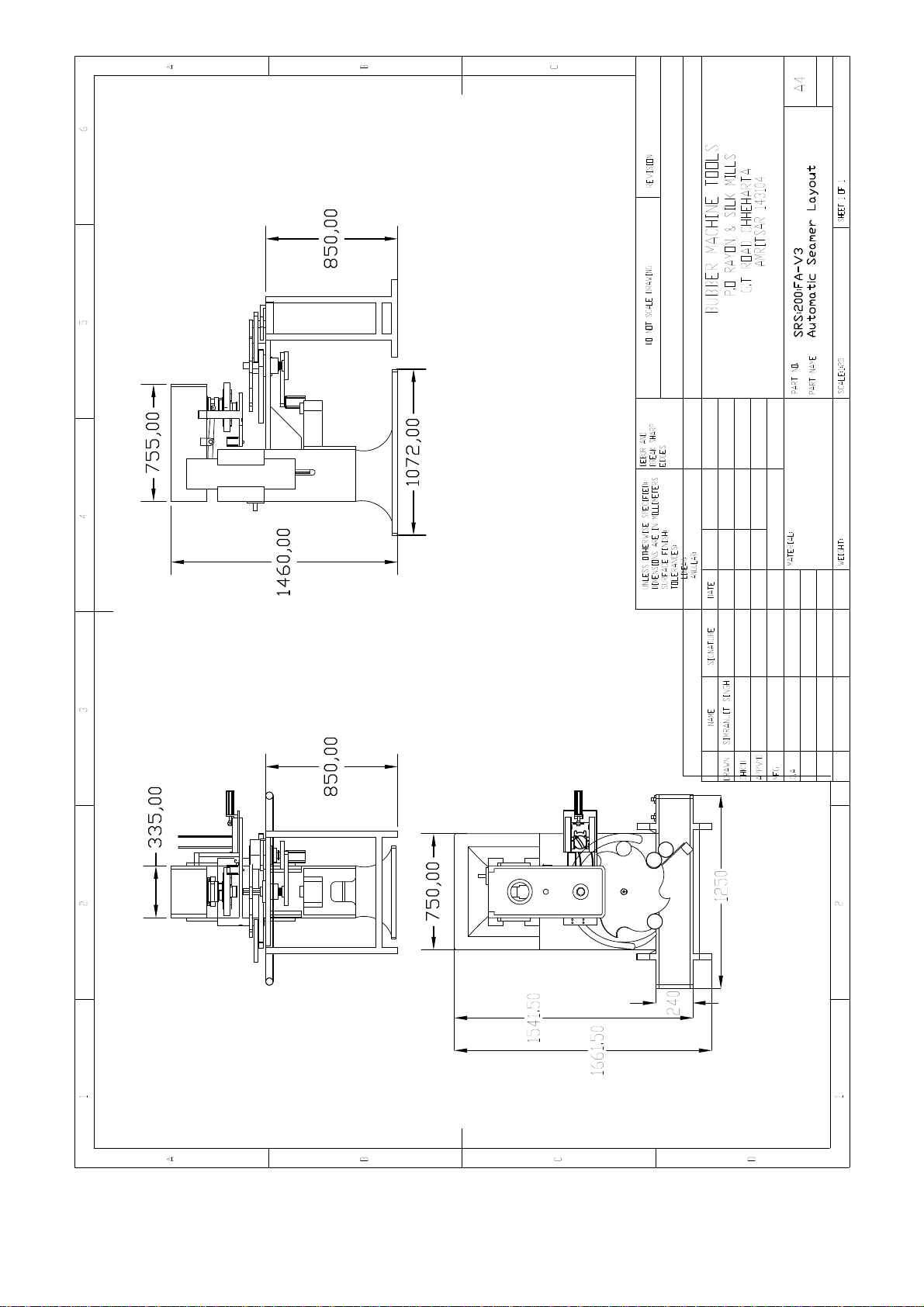
The SRS:200:FA-V3® Seamer is a single head fully automatic round can seaming machine
with lid feeder designed for continuous operation.
The machine incorporates a Conveyor, Servo Driven Indexer with a Lid Feeder in a
compact efficient package.
All logic controls and safety functions are carried out by a Programmable Logic Controller
(PLC).
Unpacking
1. The machine is packed & shipped standing up-right.
2. Remove all metal bracing rods on the crate.
3. Open the top cover of the crate first.
4. Remove the sides.
5. The box containing spares, tooling, tool kit, etc are fastened to the base of the
crate. Remove all these items prior to lifting the machine.
6. The base of the machine is bolted to the bottom of the crate. Unbolt and then lift the
machine up.
Installation
1. The Machine must be installed securely on a level surface. Holes have been
provided on the machine base to facilitate the use of dampers or other stands, if
required.
2. It should be installed in a well-ventilated area, as depending on climatic conditions
there can be heat build up in the Motor and Control Panel.
3. Ensure that there is no possibility of water or other liquids entering the Motor or
Control panel unit, solenoid vales and other electricals as this will cause the
machine to malfunction / components and pose a risk of electrical shock or short
circuit.
4. Care should be taken when handling the Proximity Sensors, as they are very
sensitive and should not be dropped, subjected to heavy vibration or wet.
5. Electrical connections must be made by as shown in the electrical diagram
attached.
6. Check the V-Belt tension. To do this, loosen the allen bolts locking the motor plate
pins on either side. Using the tool provided turn the worm wheel located behind the
motor plate to move it closer/further. One the correct tension is achieved; tighten
the allen bolts to lock the motor plate in place.
7. Properly grease and lubricate parts as shown in the lubrication plan.
8. The pneumatic system requires between 3-4 Bar of air pressure. Use the FRL to
regulate this. The Air lubricator should be filled with pneumatic grade oil, as
required.
SRS:200:FA-V3 Automatic Seamer. Delta. Rev 1.10
Page 2 of 60

9. Conveyor:
Position the conveyor as required. To facilitate easy transfer of Cans to and from
the machine, slightly slant the conveyor such that the Input side is very slightly
higher than output side.
Adjust the guides according to the size of the Can.
Connect the Motor and ensure that the direction of the Conveyor is in line with the
direction of the machine operation. Normally, Right to Left when facing the
machine.
Electrical Connections
1. All mains electrical connections are made directly to the control panel. Refer to the
attached electrical diagrams / panel layout to make the connections.
2. The machine requires 3 Phase and a Neutral connection. The input connectors are
located inside the control panel. The 3 phase and neutral are connected to the first
four terminal blocks from left to right, respectively.
3. In locations where the 3 phase voltage is higher than 440V, a Transformer will be
supplied with the machine (as ordered) and in this case only 3 phase connection
has to be made. The Neutral is internally generated by the transformer
4. The controls all work on 24VDC which is derived from the single phase connection
through a power supply unit located in the panel
5. Connect all connectors (3 in total) from the Control Panel to the appropriate
connectors on the machine. Another single, separate cable from the Panel is to be
connected to the Servo Motor lead.
6. IMPORTANT – The Seaming head must rotate in the direction shown by the ‘Arrow’
label on the machine. After making connections, check the direction by pressing the
Motor Inch button. To reverse the direction invert any two phases at the Control
Panel 3 Phase input or the Motor Terminals. Do the same with the conveyor to
ensure it moves in the right direction.
7. Earth (Ground) points have been provided on both the motor and the panel. The
machine should also be ground separately at any suitable point.
Touchscreen Controls and Display
All machine operations and logic settings are carried out through the Touchscreen
controller on the machine. In normal operation, the Display is Green and indicates
the current status. When there is an Alarm, the Display will glow Orange and
indicate the Alarm Status.
Refer to the Attached Sheet showing the different Screens and description of
Controls / Operations.
SRS:200:FA-V3 Automatic Seamer. Delta. Rev 1.10
Page 3 of 60

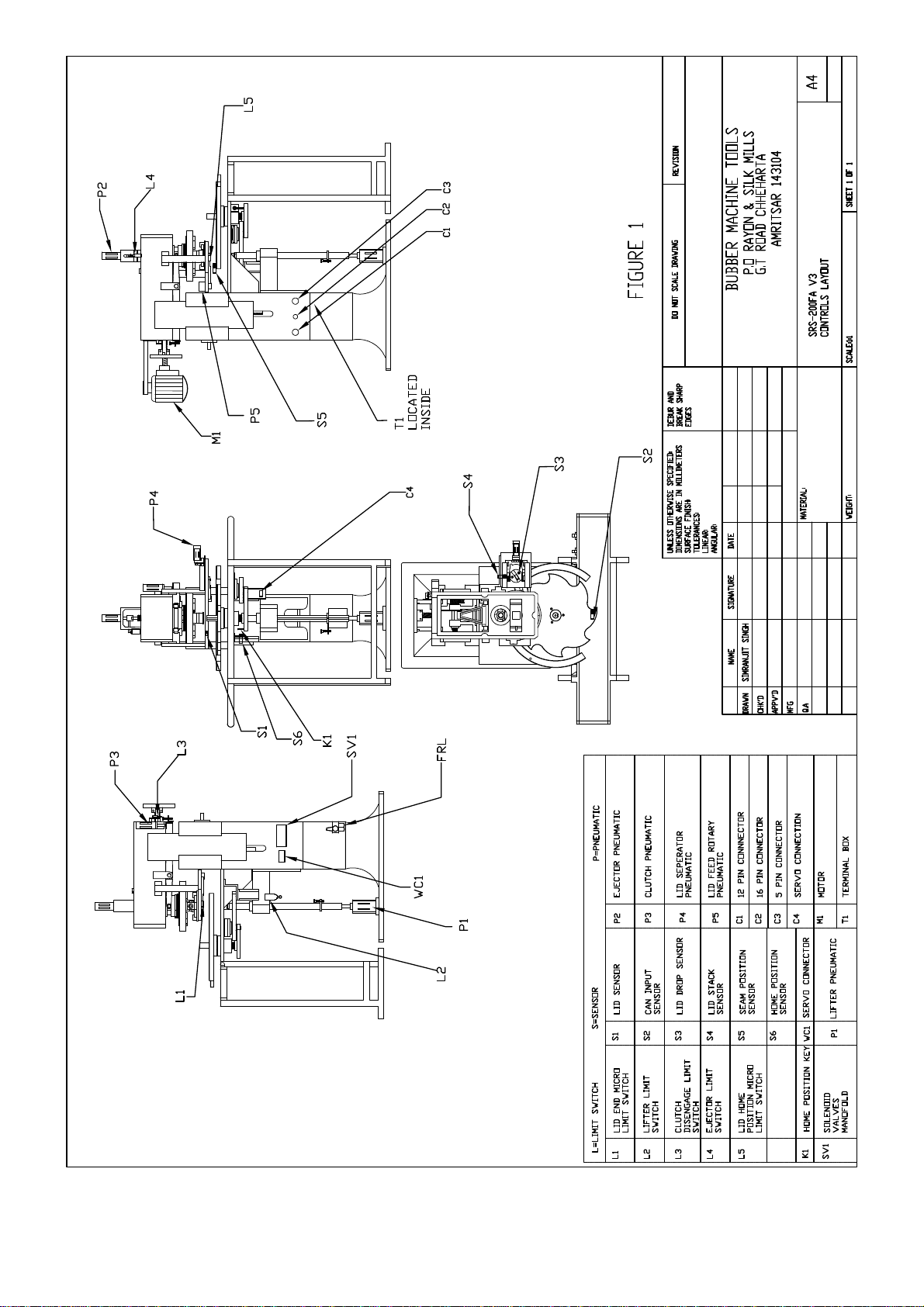
!Machine Home Positioning
One first turning the Power ON, the Touchscreen will prompt for the machine home
positioning. This is vital to ensure that the Indexing wheel is at its Home position with
reference to the Seaming Chuck. This ensures that the Indexing Wheel brings the Can to
the right position so that the Can, Lid and Seaming chuck are perfectly aligned.
On pressing the Home position Icon, the indexer will rotate and stop at its given/set Home
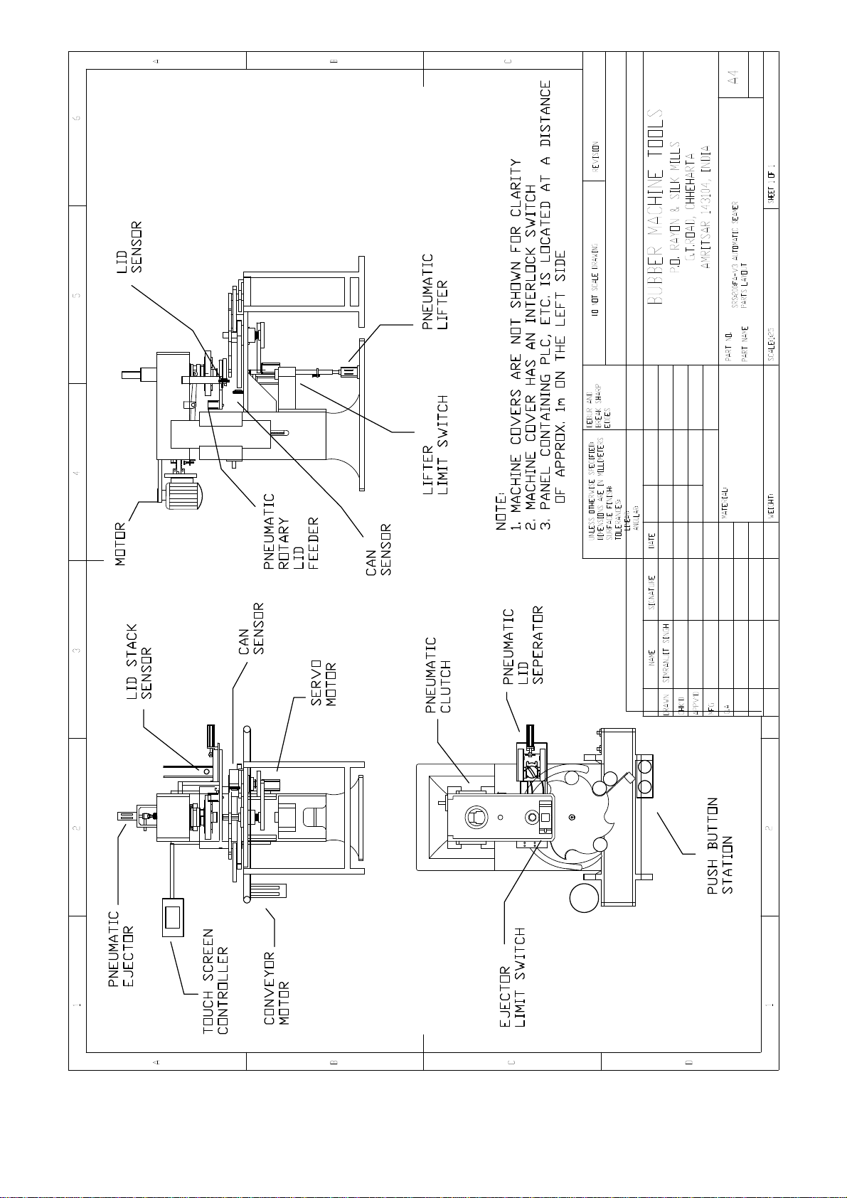
Position. This positioning is done with the help of a Proximity Sensor and Key as shown in
Figure 1 (S6 / K1). Refer to instructions below to RESET the Home position in case it is
disturbed.
NOTE: RUNNING THE MACHINE WITHOUT PROPER HOME POSITITIONING CAN
RESULT IN SEVERE DAMAGE AND/OR IMPROPER SEAMING.
HOME POSITIONING SHOULD ALWAYS BE CARRIED OUT AFTER A JAM, POWER
OUTAGE OR IF THE INDEXER IS MANUALLY MOVED WHILE IN REST POSITION
ENSURE THAT THERE ARE NO CANS IN THE INDEXING WHEEL DURING HOME
POSITIONING OR IT WILL CAUSE AN ACCIDENT.
RESETTING HOME POSITION
When the Home Icon is pressed, the Indexer rotates slowly to find the Home position. This
is achieved by means of a Key and Proximity sensor located below the table. When the
Sensor switches ON, the Home position is set. The Home position has been factory Set
and does not need to be altered or changed unless it is moved.
In the event that the home position is disturbed (Can is not aligning with the Lid and
Chuck), follow the procedure below to reset the same:
a) Switch OFF the machine so that the Indexing Wheel can be freely rotated by hand.
b) Place a Can on the table and manually move it forward to the Seaming station
c) Raise the Seaming Head up by about 4”
d) Reverse the air connections on the Can Lifting pneumatic cylinder to lift the Can up.
e) Slowly lower the Seaming head till the Can, Lid and Chuck are properly aligned.
The Can should be fully seated in the Lid while the Lid should be seated in the Can.
You may need to rotate the indexing wheel manually while bringing the head down
to ensure proper alignment.
f) Where the Can is properly aligned with the Seaming Chuck is the correct Home
Position.
SRS:200:FA-V3 Automatic Seamer. Delta. Rev 1.10
Page 4 of 60

g) Adjust the Sensor and Key so that the point where the sensor comes ON is where
the Indexer stops at its correct Home Position.
h) Mark the Home position Station on the Indexing Wheel (if not already marked)
i) Change the Pneumatic Cylinder connections back to normal to bring it down and
Remove the Can by manually turning the indexing wheel.
j) Now rotate the Indexing wheel and introduce a Can in the Home Position station on
the Indexing Wheel (as marked above). Position the indexer such that the Can is
before the seaming station.
k) Power ON the machine and press the Home Position Icon. The Indexer should
slowly move forward and stop at its Home Position with the Can directly below the
seam station.
l) Raise the Can up using the Controller and check for alignment. If OK, the machine
is ready to operate.
If not, OK repeat the process above and fine tune till the proper setting is achieved.
This may take a few times to get the absolute right position.
SRS:200:FA-V3 Automatic Seamer. Delta. Rev 1.10
Page 5 of 60

Sequence of Operation
1) The Can is brought to the input position on the Indexing Table.
2) A sensor detects the Can and:
a. Indexes the Can One station forward
b. The Lid sensor checks for the presence of a Lid. If a Lid is not present, One
is dropped and Fed to the seam station.
3) When the next Can is brought to the indexer Input station, it is further indexed one
position and the above condition regarding the Lid is checked.
4) Each time a new Can is brought to the indexing station, the indexer moves forward
one position at a time. Initially it is rapidly moved forward until a Can is brought
under the Seam station.
At the Seam Station
1) Once a Can is detected at the Seam Station (Can Sensor), it is lifted by means of
the pneumatic cylinder (Figure 1, P1) to the Chuck. At the top position a Limit
Switch (Figure 1, L2) is depressed indicating the Can is lifted. The Clutch is
engaged by means of the Pneumatic Cylinder (Figure 1, P3) and the Seam
operation begins. (refer to the section on Roller setting to understand the
operation).
Note: After engaging the clutch, the pneumatic cylinder retracts. It does not need to
hold the Clutch in the engaged position. The clutch disengages mechanically after
the Seam cycle is completed
2) After Seaming is completed, the clutch disengages. The Limit Switch (Figure 1, L3)
at the rear is pressed to denote completion of the Seam Cycle.
3) The Can is brought down and as soon as the Lifter Limit Switch (L2) is released,
the Ejector (Figure 1, P2) is brought Down to ensure the Can is released from the
Seaming Chuck.
4) A previously separated and dropped Lid is Fed to the Seam position by the Lid
Feed rotary pneumatic cylinder (Figure 1, P5)
5) Provided there is a Can at the Input Station of the Indexing wheel, the Seamed Can
is indexed one station forward.
6) If the Can gets Jammed to the Seaming chuck and the Ejector is unable to press
the limit switch (Figure 1, L4), an Alarm is given and the machine is turned OFF.
The Indexer will not move forward in this condition.
SRS:200:FA-V3 Automatic Seamer. Delta. Rev 1.10
Page 6 of 60

Settings
Seaming Chuck:
The Seaming chuck has a threaded holder and simply needs to be screwed on. Please
note that it is an opposite thread and is tightened in the same direction of rotation as
the seaming head. The Seaming Chuck is made specifically for a Can Size and Lid
Type. The tolerances of the Lid must be within 0.05mm to the original size against
which the chuck is supplied.
Seaming Roller Settings:
The machine has 4 Rollers. 2 x 1st operation rollers and 2 x 2nd operation rollers. 1st
operation rollers (thinner grooves) are mounted on arms no. 1 & 3 (opposite each
other) whereas 2nd operation rollers (larger grooves) are mounted on arms no. 2 & 4
(opposite each other). A double Cam controls the movement of the Rollers. The top
part of the Cam for the 1st operation and bottom for the 2nd operation.
During Seaming, the drive to the Cam is given by engaging the Clutch. The 1st
operation rollers are brought in gradually for about 4.5 rotations and then rapidly
retracted. These form the Hook in the Seam.
The 2nd operation rollers are then brought in for about 1 rotation to press the Hook into
forming the Final Seam after which the clutch disengages.
The quality of the seam depends mainly on the Seaming rollers and their setting.
Please carry out the settings as described below. Also refer to the Video guide provided
for setting the Rollers.
1. Pressure Setting:
To adjust the pressure of the rollers, the seaming arm/lever (SA-49) must be moved
inwards or outwards. To do so, loosen the bolts on the Cam Follower Lever (SAV-40) of
the corresponding lever. Then move the Seaming arms inwards/outwards to achieve
the desired setting. Once the setting is done these should be locked in place and the
bolts tightened completely.
The pressure is set at the maximum inward travel of the rollers. The maximum travel is
the highest point on the Seaming Cam corresponding to that lever.
First move the levers out. Now engage the clutch and manually rotate / inch the head
for ~4.5 rotations. This is the position where the bearings mounted on the Cam
Follower Levers (1st operation) are at the top most position and the seaming pressure
is maximum.
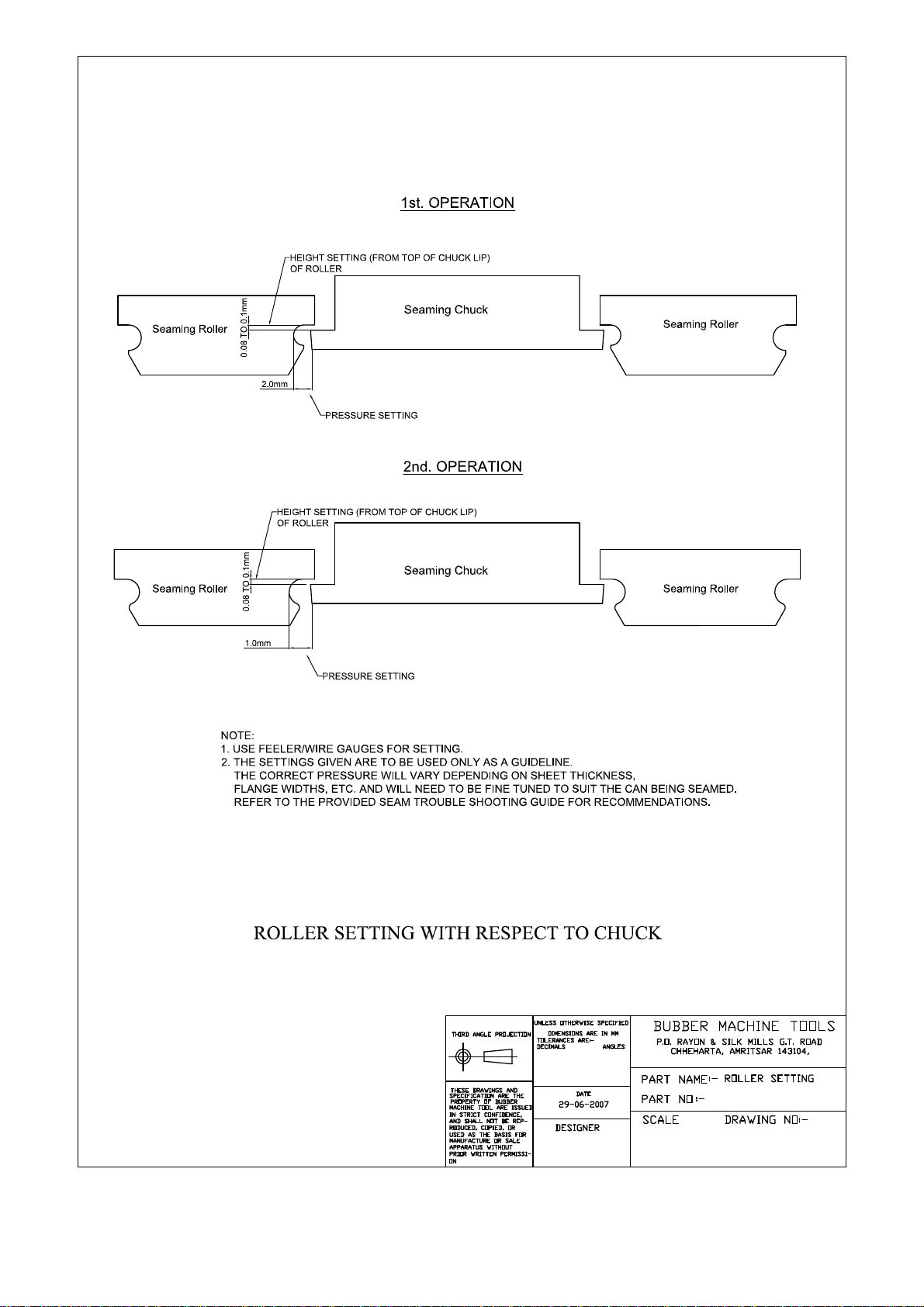
At this point adjust the 1st operation rollers by moving them inwards till the gap
between the lip of the seaming chuck and roller groove is as per the attached drawing.
Fully tighten the bolts on the corresponding Cam Follower Levers.
SRS:200:FA-V3 Automatic Seamer. Delta. Rev 1.10
Page 7 of 60

After setting the 1st operation rollers rotate the head for a further 1 rotation. This is the
position where the bearings mounted on the Cam Follower Levers (2nd operation) are
at the topmost position.
At this point adjust the 2nd operation rollers by moving them inwards till the gap
between the lip of the seaming chuck and roller groove is 1mm.
Use a feeler gauge for making the adjustments.
Note: The actual required roller pressure depends on the flange widths, sheet material
thickness, etc. and hence needs to be set differently for each type of can for which the
operator must use their best judgment. Refer to the attached Seam trouble shooting
guide for assistance.
2. Roller Height Setting:
To adjust the roller height, the entire roller assembly must be raised or lowered. To do
so, loosen the bolt located on top of the roller pin (above the seaming lever). Rotate the
roller with a spanner to the desired height and then tighten the bolt. The correct height
is when the lip of the roller is just free of the lip of the chuck (Typically between 0.08
and 0.1mm). Tighten the bolt above the roller once set.
This setting can be done at the same time when adjusting the roller pressure.
Can Height Setting
The machine can accommodate various Can heights within permissible limits.
To change the height the entire Seaming head assembly has to be moved upwards or
lowered as required. This is done by loosening the bolts on the adjustment slides (SAV-
167) and turning the Height Adjustment Wheel (SAV-79) to raise / lower the head
assembly. Refer Figure 7.
When changing from a larger to smaller height Can, place the Can on the base plate
and lower the head till the chuck sits tightly on the Can.
When changing from a smaller to larger height Can, first raise the head and then lower
it onto the larger height Can.
The correct height setting can be noted from the position of the Pin in the main lifting
shaft (refer Figure 7). With a Can in place, lift the shaft using the Touchscreen. The
right height setting is when the Pin in the shaft is at the centre position.
Once the desired height level has been achieved, tighten all the bolts on the slide ways.
Do not operate the machine with the bolts in a loose position as this can cause the
slides to slip and may result in damage to the machine.
No adjustments to the Can movement arms are required for Can height changes. The
Seaming Chuck and Rollers also need not be adjusted.
SRS:200:FA-V3 Automatic Seamer. Delta. Rev 1.10
Page 8 of 60

Lid Feed System
The lid feeder uses a pneumatic separator with a pneumatic feeder. Each time a Can is
sensed on the machine, a lid is dropped by the separator and then fed by the arm to
the Seam position under the seaming chuck. It is then picked up by the Can when it
moves upward to be seamed.
Sensors are provided at the Lid drop position and at the Seam Position. A Lid will be
dropped and fed to the Seam position whenever a Can is first sensed at the Indexer
input station. The
The blades used on the separator are made according to the Lid height and no
adjustments are required, unless there is a change in dimensions.
Note that the Lid Separator / Feeder are highly sensitive to dimensional variations. All
dimensions are to be maintained within 0.10mm of the original. Any deviation may
cause the Lid Feeder to Jam and malfunction.
A sensor is provided at the Lid Stack to ensure sufficient lids are always in the stack. In
the event that the number of lids goes below the minimum required, the machine will be
put OFF and an Alarm will be given on the Display.
The Lid Separator and Feed Pneumatic Cylinders are provided with speed control
valves. Adjust the speed so that both operations are carried out smoothly
without any jerks.
Refer Figure 5
SRS:200:FA-V3 Automatic Seamer. Delta. Rev 1.10
Page 9 of 60

Machine Operation
1) After powering up the Control Panel using the MCB, wait 10 seconds for the PLC &
Servo to initialize before pressing any other Button or running the machine.
2) Press the Icon for HOME Positioning and ensure that the same is properly done.
3) Before running the machine, make sure that all moving areas are clear of any tools and
foreign materials. If any settings have been made double check them.
4) Ensure that the Lid Stack has sufficient Lids, at least a few inches above the lid stack
sensor.
5) The Emergency Switch is not pressed. When pressed, the Display will be Orange with
an Alarm indicating this status.
6) To start the machine, press and hold the RUN Icon. To Stop, press the STOP Icon on
the Touchscreen Controller.
7) Run the machine briefly for a few seconds to ensure that it is running smoothly.
8) In the event of a problem immediately switch the machine OFF using either the
Emergency Switch or the Icon on the Touchscreen. Do not restart the machine till the
problem has been identified and corrected.
SRS:200:FA-V3 Automatic Seamer. Delta. Rev 1.10
Page 10 of 60

Size Changeover
Follow the instructions below to change from One Size to the other:
Height Change Only:
If there is only a change in the height of the Cans, no parts are required to be changed.
Simply adjust the height of the Can as outlined above.
Diameter Change:
To change from One diameter to another, the Indexing Wheel, Lid Feed System, Guides
and Seaming Chuck need to be replaced (refer to Figure 8). Follow the procedure below.
a) Raise the height of the Head to provide sufficient clearance.
b) Remove the Indexing Wheel.
c) Remove the Guides.
d) Remove the Sensors on the Lid station.
e) Remove the Lid Station.
f) Remove the Seaming Chuck and Ejector.
g) Loosen the Cam Follower Levers (SAV-40) and move the Roller levers outwards.
Then:
a) Put in the new Seaming Chuck and Ejector
b) Set the Seaming Roller pressure and height
c) Affix the Lid Seaming Station and Sensors
d) Affix the Guides
e) Affix the Indexing Wheel
f) Adjust the Conveyor guides and guide at the Can Input station.
g) Adjust the Can input Sensor
h) Adjust the Sensor at the Seaming Station
i) Set the Seaming Head height
j) Fine tune the Roller Pressure if necessary
SRS:200:FA-V3 Automatic Seamer. Delta. Rev 1.10
Page 11 of 60

Electrical Components
Refer to attached Electrical Layouts and I/O diagram.
1) PLC
This is a Programmable Logic Controller programmed according to the machine
requirement. A copy of the ladder diagram is part of this manual.
2) Sensor
This is a 24VDC Proximity Sensor that sends a pulse to the PLC. It has a maximum
sensing distance of 15mm but for practical purposes should be positioned at a
distance of 8-10mm. It can be moved back and forth simply by loosening the nuts
provided on the unit. The sensor is a highly sensitive electrical component and care
should be taken that it is not subjected to impact or any liquid dropped on it. It may
be clad in a clear plastic sheet if necessary.
3) Emergency Switch
An emergency switch has been provided at the Can feed end of the conveyor. In the
case of an accident the operator may press the Emergency Switch. This will shut off
all electrical supply to the motors and the machine will turn “OFF”. Once pressed the
switch gets locked in the “OFF” position and must be turned to unlock it and pop-up
to the “ON” position.
4) Servo Motor
The Servo Motor gives the drive to the Rotary Indexer. It has a very high precision
encoder which ensures that the positioning is 100% accurate. In the event of a
machine Jam or overload, the Servo motor will trip and an indication will be given on
the Display (Orange). To reset, turn the Power OFF, wait a few minutes and then
Power ON again.
5) Control Panel:
The control panel incorporates the following:
a) Rotary Power Switch
b) Power ON Indicator.
c) MCB: Miniature Circuit Breakers for all components
d) A 100-250VAC to 24VDC stabilized Power Supply is provided for a regulated DC
supply.
e) Servo Motor Amplifier and Power Supply
f) Motor Contactors
g) PLC
Please refer to attached Electrical Drawing no. 2 for layout.
SRS:200:FA-V3 Automatic Seamer. Delta. Rev 1.10
Page 12 of 60

Safety Features
1. Emergency Switch:
When pressed during machine operation, the machine will be brought to a halt in
0.5 seconds and all functions will stop. No function will work till the Emergency
Switch is released. The Green light on the panel will blink slowly when pressed. The
emergency switch also acts as a reset button in the event that the machine is
stopped by any other error. It must be pushed and released to restart the machine.
2. Can Ejector:
A pneumatic can ejector is provided to ensure that the Can does not get stuck onto
the chuck after seaming. It gets its input signal from the sensor located on the main
table towards the front of the machine. Once descended the Ejector is retracted
when it presses the limit switch located next to it. If the limit switch is not pressed
within 1 second, the machine is brought to a stop.
To reset, first press the emergency switch and determine the cause of the jam and
clear the machine. Remove any lid that may be present under the chuck. Release
the emergency switch and restart the machine.
3. No Can - No Lid System:
A Lid is dropped by the Lid separator only when a Can is sensed to be brought to
the seam station.
4. Lid Stack Sensor
This sensor checks for the presence of lids in the lid stack. When the level of lids
goes below the sensor level, the Yellow indicator blinks for about 5 seconds after
which the machine is shut OFF. Replenish the Lid stack and reset by pressing and
releasing the Emergency switch.
5. Lid Sensor:
A Lid sensor is provided in the lid feeder just below the chuck, in the position where
the Lid is finally placed prior to be picked up by the can for seaming.
When the Can is lifted to be seamed at the seam station, the Lid sensor will check
for a presence of a Lid. If no lid is present, the machine will be stopped within 0.5
seconds. The Display will indicate the error..
6. Electrical Overload:
The Servo has a built in protection system. In the event of an overload or jam in the
Servo, the machine will be switched off and the Display will indicate the error.
The Control Panel has MCB’s for all components. These will trip on overload of any
component. Please check and isolate the fault in the event of a trip before
restarting.
SRS:200:FA-V3 Automatic Seamer. Delta. Rev 1.10
Page 13 of 60

Care & Maintenance
1. Always Disconnect the main power supply before attempting to change any Wiring
or make any Connections including the Control Panel to the Machine.
2. Ensure that no water or other liquids are allowed to enter the Motor, Starter, Control
Panel or other electricals.
3. Proper Lubrication must be provided to all points indicated on the Lubrication Plan.
4. Painted parts may be cleaned with Mild Detergent. Do not use thinner or other
Industrial Cleaners as these may spoil the finish.
5. Perfect Seaming Can be achieved by proper maintenance of the machine, most
importantly the Seaming Rollers and Seaming Chuck.
6. Check and tighten all bolts, etc. every month.
7. The FRL unit must be drained of any water and oil level in the lubricator must be
checked daily.
SRS:200:FA-V3 Automatic Seamer. Delta. Rev 1.10
Page 14 of 60

Checklists
2) Can Height Setting
a) Lower or Raise Seaming Head.
b) Tighten all bolts on Height Adjustments guides.
3) Roller Setting
a) Roller Pressure and Height with respect to the Chuck is set and adjusted as
needed.
4) Final Check prior to Running
a) Check Motor Rotation (remove V-Belt and re-attach when direction verified).
b) Check direction of Rotation of Conveyor.
c) Clear the machine of all Cans.
d) All parts lubricated. Sufficient Oil is present in the Oil reservoir.
e) Guides Adjusted.
f) Sensors Adjusted.
g) Sufficient Lids are present in the Lid Stack of the Lid Feeder.
h) All safety covers closed and safety interlocks activated.
i) Speed of Pneumatic valves is adjusted for smooth running.
j) Emergency switch in “OFF” position.
k) Sufficient Lids placed in the Stacker.
l) Manually inspect machine for any tools or foreign objects in the Can & Lid path.
m) Check the FRL gauge for sufficient air pressure. The optimum pressure should be
between 3-4 Bar and maintained at the set level.
SRS:200:FA-V3 Automatic Seamer. Delta. Rev 1.10
Page 15 of 60
SRS:200:FA-V3 Automatic Seamer. Delta. Rev 1.10
Page 16 of 60
SRS:200:FA-V3 Automatic Seamer. Delta. Rev 1.10
Page 17 of 60
SRS:200:FA-V3 Automatic Seamer. Delta. Rev 1.10
Page 18 of 60
SRS:200:FA-V3 Automatic Seamer. Delta. Rev 1.10
Page 19 of 60

SRS:200:FA-V3 Automatic Seamer. Delta. Rev 1.10
Page 20 of 60
Table of contents


