Somat SPC50 User manual

SO1000 11/20
Operation Manual
SPC50/SPC75 Close Coupled Pulping Systems
165 Independence Ct. Lancaster, Pa 17601 (Ph:800-237-6628) (service@somatcompany.com)

2
To better serve your needs in the future, please record your
equipment’s information below.
Model Number:
Serial number:
Service Company:
Service Phone Number:
Rep/ Dealer:
Rep/Dealer Phone number:
Somat Service Dept: 800-237-6628 x176
Somat Parts: Visit SomatCompany.com for an authorized parts distributor
To expedite service or parts, please have the above information
available before you call. The serial number of your equipment is
located inside of the main electrical control panel of your Somat
equipment.

3
SOMAT COMPANY MANUFACTURES WARRANTY
SOMAT COMPANY warrants each new product manufactured by it to be free from defects in material and
workmanship under normal use and service for a period of one (1) year from the date of initial startup or 18
months from date of shipment, whichever occurs first. "Normal use and service", with respect to Pulpers,
Food Grinders, Dehydrators, Hydra-Extractors, Waste Handling and Processing Systems, shall mean the
handling only of waste items of the types approved by SOMAT®therefore and within the LIMITATIONS
THEREIN set forth, its obligation under this warranty being limited to repairing or replacing any part or
parts thereof, free of charge INCLUSIVE of labor to remove and replace, f.o.b. factory from which shipped.
This warranty shall not apply to any product or part which shall have been repaired or altered by any
person not employed or retained by SOMAT®, so as in the judgment of SOMAT®to affect its operation and
reliability, nor which has been installed, operated, or maintained contrary to SOMAT®OPERATION or
PREVENTIVE MAINTENANCE INSTRUCTION MANUALS or to other written instructions or drawings
approved by SOMAT®, nor which has been subject to misuse, negligence, or accident. This warranty shall
not apply should the SOMAT®System be initially started up without a duly authorized SOMAT®
representative present.
Except as herein expressly stated, no warranty, expressed, implied or by law, (including but not limited to any
implied warranty of merchantability or fitness for a particular purpose), is made by SOMAT; and in any event
SOMAT’S liability, whether in contract, tort, strict liability, or under any warranty, or otherwise, shall not exceed
the purchase price received by it and shall in no event include any consequential, incidental, punitive or other
special damages. No change in this warranty and limitation of liability and substitute therefore (whether
incorporated in a purchase order or otherwise) shall be effective unless specifically set forth in a written
instrument signed by an officer of SOMAT®.
STANDARD EQUIPMENT WARRANTY EXCEPTIONS
Warranty work is for defective parts or workmanship on Somat original equipment and does not
cover wear items, cleaning, or problems resulting from improper use by the end user. Any cutting blade,
rotating blade, impact bar, sizing ring, or any other cutting mechanism part damaged due to improper
waste materials or any cutting mechanism part that has been worn due to misuse may not be covered
under Somat warranty. Any motor, solenoid valve, electrical panel, junction box, or any electrical device in
Somat equipment that has been damaged by water, improper installation, electrical short from surges or
storm related strikes may not be covered under Somat warranty. Extractor screws and screens will not be
warranted for wear. Defective or workmanship related extractor parts must be submitted to Somat for
verification before credit will be issued. Line clogs that are resultant of improper feeding, clogs due to
improper line installation, leaks in areas that Somat did not fabricate (i.e. table connection), leaks due to
improper pipe bracing, tampering with system settings, jams due to non-waste stream items or jams due
to dull/missing cutting mechanism parts, alterations to equipment without prior Somat approval or any
other action that could cause harm to the equipment’s performance may not be covered by Somat
warranty.

4
Table of Contents:
SPC-75S, SPC-75UDT, SPC-50S SPC-50UDT
Introduction……………………………………………………………………………...
Safety Precautions and Warnings…………………………… 5-7
General Description & Definitions……………………………. 8-11
Installation……………………………………………………….……………………… 12
Unpacking……………………………………………………………………... 13-15
Mechanical Installation……………………………………………… 16-18
High Tank Models
UDT Models
Mounting of Grabber Magnets
Plumbing Installation………………………………………………… 19-20
Fresh Water
Hydra-Extractor Overflow and Pulper Drain
Return Piping for Units with a Tray Feed Only
Return Piping for Units with a Trough
Electrical Installation…………………………………………………… 21-22
Panel & Optional Remote PBS Mounting
Supplying Som-A-Trol with Power
Remote Push Button Station
Start-up……………………………………………………...………………………….... 23
Warranty Registration Form…………………………………...… 25
Operation………………………………………………………………………………… 26
Typical Operating Procedure……………………………..…… 27
Shutdown Procedures………………………………………………. 28
Light Codes…………………………………………………………………… 29
Special Operating Procedures………………………………… 30
Cleaning Your System...………………………….……………………………. 31
Cleaning Instructions…………………………………………………. 32
Cleaning the Pulper……………………………………………………. 32
Cleaning the Hydra-Extractor
Cleaning Compounds………………………………………………… 33
Maintenance………………………………………………………………………………………... 34
Periodic Maintenance and Inspection…………………… 35-36
Component Removal and Replacement…………….… 37-42
Troubleshooting…………………………………………………………………….. 43-46
Display Module Instructions…...…………………….……………………. 47-51
5
Safety Precautions and Warnings
READ THE MANUAL
COMPLETELY BEFORE ATTEMPTING TO OPERATE THE UNIT.
HIGH VOLTAGE!
DO NOT PERFORM ANY REPAIRS TO MOTORS OR CONTROL
SYSTEMS WITHOUT TURNING OFF THE MAIN POWER.
ALWAYS
TURN THE MAIN POWER OFF
AND LET ALL MOTORS COME TO A
STANDSTILL BEFORE DOING ANY MAINTENANCE ADJUSTMENTS OR CLEANING OF
THE UNIT.
BEFORE STARTING, BE SURE
ALL PERSONNEL ARE CLEAR
OF MOVING PARTS.
KNOW LOCATION AND FUNCTIONS OF ALL
START/STOP BUTTONS
AND SAFETY
SWITCHES.
DURING PERIODIC MAINTENANCE,
CHECK ALL SAFETY SWITCHES
TO BE SURE
THEY ARE OPERATING PROPERLY.
DO NOT REMOVE
OR ALTER GUARDS.
DO NOT REMOVE
SAFETY LABELS. IF LABELS ARE MISSING OR DESTROYED,
CONTACT FACTORY FOR REPLACEMENT.
DO NOT OBSTRUCT
ELECTRICAL PANELS OR PUSH BUTTONS.
GOOD HOUSEKEEPING
IS THE MOST IMPORTANT SAFETY PROCEDURE.
6
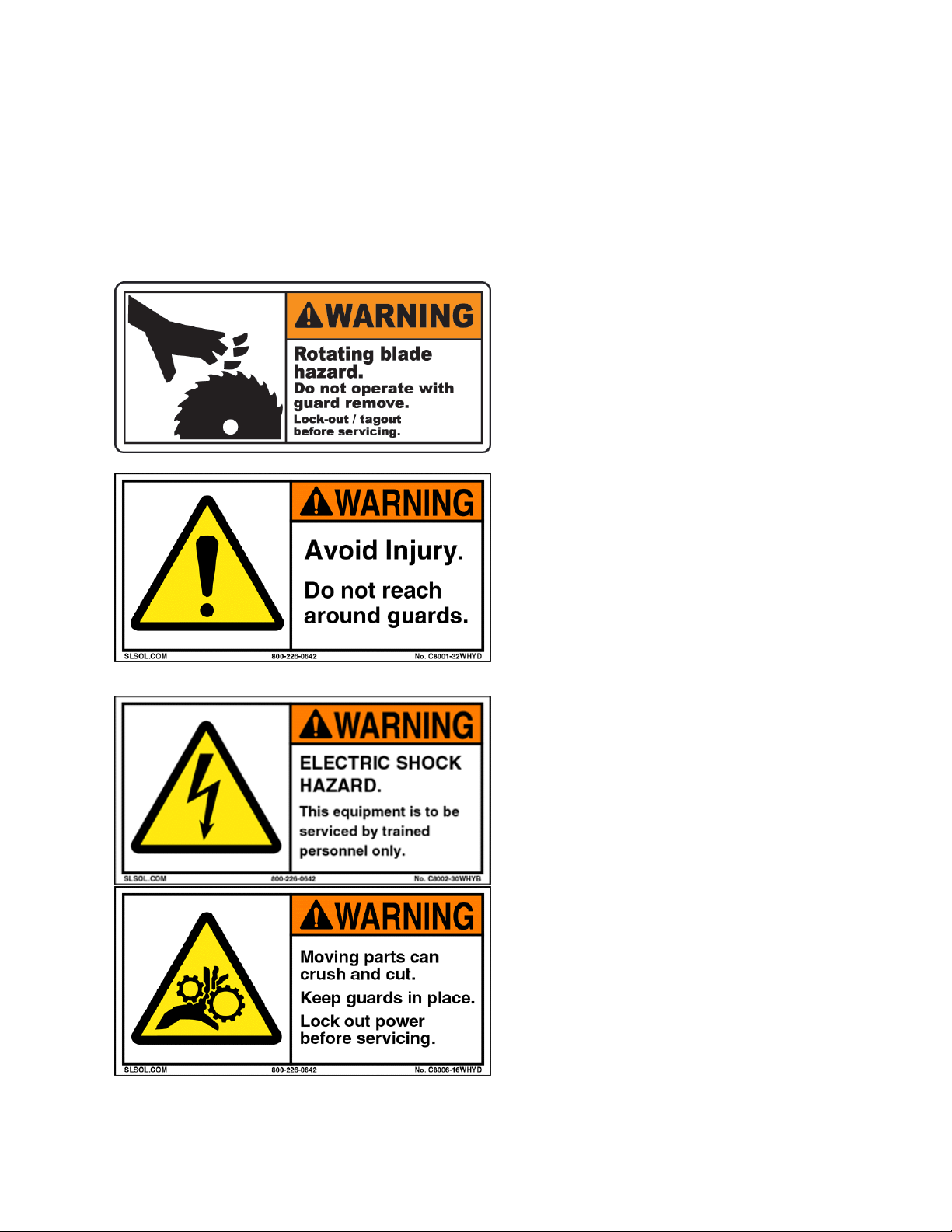
Safety Precautions and Warnings
This equipment has locations which are hazardous and cause severe injury or death if
warnings are not followed. Always turn off power before reaching into any unit!
Maintenance to be performed by trained and authorized personnel.
This equipment has moving parts operating
at high speeds! Death or serious injury can
occur if warnings are not followed.
This equipment has moveable lids
protecting you from moving parts. Do not
alter safety devices or guards. Do not reach
into any part of the unit with the power
turned on.
This equipment uses High Voltage! Only
trained and authorized personnel should
perform maintenance on the electrical
components of this machine.
This equipment has moving parts that can
crush and cut. Do not alter safety devices or
guards. Do not reach into any part of the
unit with the power turned on.

7
Caution: Damage will occur to this equipment if unsafe objects are fed into the
machine(s). Keep these items out of the machine(s) to avoid component failure and
unwanted downtime. When in doubt, keep it out of the machine(s)!
Glass, Bottles, Jars
Cans Silverware
Metal of any kind!
Pans China Wood
Towels / Rags Scrub-Pads
Always turn the power off before servicing the pulper!

8
GENERAL DESCRIPTION
The SOMAT® system prepares solid waste materials for disposal by transforming the
materials, with water, into a pulp. This transformation takes place in a unit called a Pulper
which is designed to pulp all forms of paper, plastic, cardboard and food waste. The waste
material is fed manually or automatically to the Pulper. The continual down flow of water
and the rotation of the Pulper impeller create a strong vortex action which pulls the waste
down against the cutting blades of the impeller. The resultant slurry is then forced through
a perforated stainless-steel Sizing Ring surrounding the impeller.
9
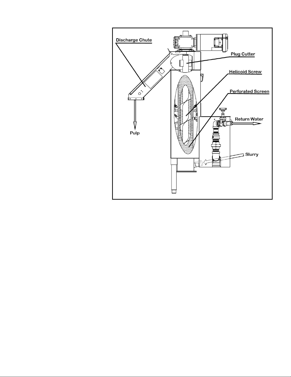
The SOMAT® System is
designed to pump the
mixture of macerated solids
and water, called slurry, to
the Hydra-Extractor® where
the slurry is reduced to a
semi-dry pulp. Within the
Hydra-Extractor®, the slurry
is carried by a helicoid
screw within a perforated
tubular screen. The water
passes through the screen
and is pumped back to the
pulping unit. The solids
continue up the helicoid
screw to a compression
chamber or plug area where
additional water is removed
by extrusion. The solids in
this area are called the plug.
This plug is broken up at the
Hydra-Extractor® discharge
opening by a cutter and the
pulp then falls out of the discharge chute.
This system can reduce the volume of average non-compacted waste by approximately 80
percent.
The system is powered by electric motors with the associated controls housed in Som-A-Trol
(electric control panels). Since, in the course of operation, some water is absorbed by the pulp,
fresh make-up water is supplied to the Pulper automatically through a solenoid valve.
In addition to the basic system as discussed to this point, numerous additional items of
equipment may or may not be required to comprise a specific system.
TYPICAL HYDRA-EXTRACTOR®

10
DEFINITIONS – GENERAL
Pulper - device that contains an impeller and sizing ring to grind solid waste. The
resultant mixture of waste particles and water is called slurry.
1. Hydra-Extractor® - Inclined screw-type press for removing transport water from pulp.
2. Slurry - A water solution containing a low percentage of suspended solids.
3. Pulp - Semi-dry solid from which transport water has been extracted.
4. Som-A-Trol® - Electrical control panel, including motor starters and sequencing
controls for automatic operation of the SOMAT® system.
5. Slurry Pump - Specially designed pump used to transport slurry from a SOMAT®
Pulper to Hydra-Extractor®.
6. Return Pump - Specially designed pump used to return water from Hydra-Extractor®
to SOMAT® Pulpers.
7. Water Level Control - a PLC controlled function utilizing time-based programming.
8. Chemical Additive Pump - A proportioning type Additive pump that adds de-foaming,
deodorizer, and/or buffering solutions to the process water.

11
DEFINITIONS –COMPONENTS
SOMATPULPER:
1. Tank - Pulping or grinding chamber of the SOMATPulper.
2. Impeller - Rotating metal plate with Tungsten Carbide Blades which de-fiber and
pulp the waste and along with the Security Ring provides a shearing action for
non-fibrous waste.
3. Security Ring - Perforated stainless-steel ring surrounding the impeller through
all slurry must pass after waste is pulped. Dimensions of security ring holes
controls particle size of materials leaving the Pulper.
4. Junk Box - Chamber in bottom of tank that segregates non-pulpable materials
from tank.
HYDRA-EXTRACTOR:
1. Screw - Vertical helix which lifts and compresses solids from the slurry and
permits water to drain off by gravity.
2. Screen - Mesh screen that surrounds the screw, through which water drains off.
3. Plug - Mass of pulp extending beyond last helix of the screw. The force required
to extrude the plug squeezes additional water from pulp.
4. Brush - Nylon brush attached to edge of screw helix which serves to clean the
screen.
5. Plug Cutter –Assists in breaking apart waste to discharge down the chute
GENERAL:
1. Throttling Valve - Full ported gate valve used to control water flow.
2. Timer - Electrical device used to automatically shut down the SOMATSystem at
a pre-determined time.
3. Fresh Water Solenoid - Electric valve used to control freshwater make-up to the
SOMATSystem.
4. Motor Operated Valve - (MOV) Electric valve used to drain water from tank and
lines for daily maintenance.
5. PLC- Computer controller designed to handle pulper and extractor operation.

12
Installation

13
UNPACKING
The crate containing your SOMAT® Pulper will contain the following items:
1. Pulper
2. Tray, if so equipped
3. Som-A-Trol® Panel
Misc. parts box containing:
ALL UNITS:
Anti-Vibration Pads
Installation Drawings
2
1
3

14
UDT UNITS ONLY:
1. Stainless Steel Lid
2. Stainless Steel Adapter (Unless shipped directly to table manufacturer).
3. UDT Gasket (on unit)
TRAY ONLY:
1. Return Water Assembly
TROUGH ONLY:
1. Trough Gasket & Hardware
2. Trough Nozzles & Throttling Gate Valves
(See Installation Drawing for quantity)
1
1
2
3
1
2
15
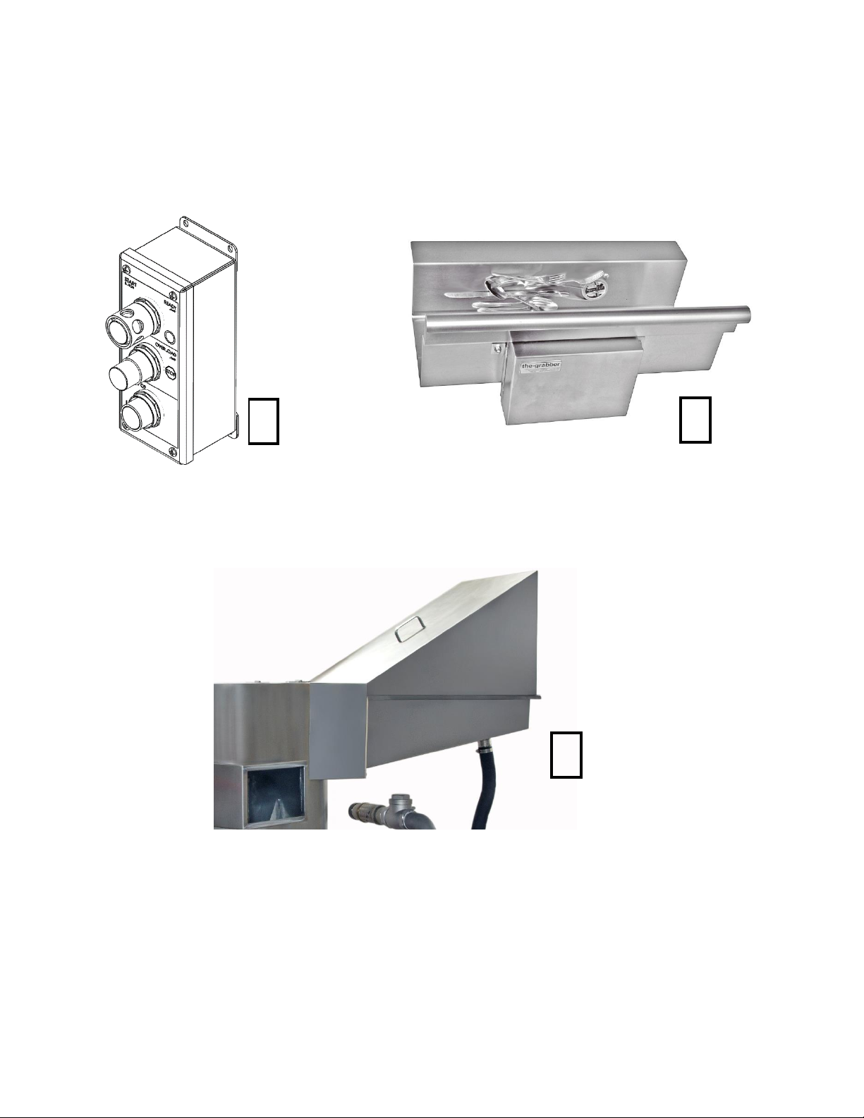
OPTIONAL EQUIPMENT:
1. Remote Push Button Station
2. Trough Magnet & Hardware
3. Tray Feed Hood
1
2
3
16
MECHANICAL INSTALLATION
HIGH TANK MODELS:
1. Put the pulper/extractor into position as shown on the Installation Drawings.
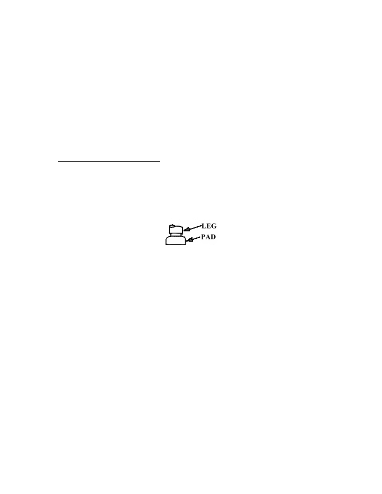
2. Place the Anti-Vibration Pads under each leg of the Pulper and Hydra-Extractor®. *
3. TRAY FEED UNITS ONLY - Install the tray to the Pulper (if it was not already installed
at the factory) using the provided gasket material and hardware.
4. TROUGH FEED UNITS ONLY - Install the provided trough gasket between the Pulpers
inlet and the trough outlet and secure with the provided hardware.
*
17
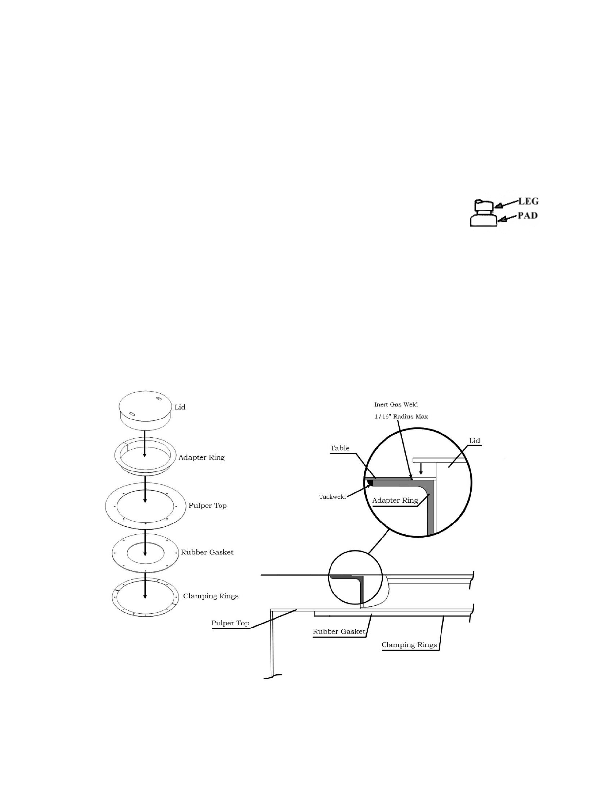
UDT MODELS:
1. Cut a hole in the top of the table as shown on the drawing (If not done by table
manufacturer).
2. Center the provided UDT Adapter beneath the opening and weld it into place as shown.
Please follow print detail for welding instructions (if not done by table manufacturer).
3. Put the Pulper into position.
4. Place the anti-vibration pads under each leg of the Pulper and Hydra-
Extractor®.
5. Adjust the Pulper and Hydra-Extractor® legs so that the unit sits level and the rubber UDT
gasket provides a watertight seal with 2” clearance between Pulper top and the
underside of the table.
6. Install the provided trough gasket between the Pulpers inlet and the trough outlet and
secure with the provided hardware. Holes will need to be drilled in the field
7. Trim UDT Rubber Gasket to fit tightly around the pulper lid.
18
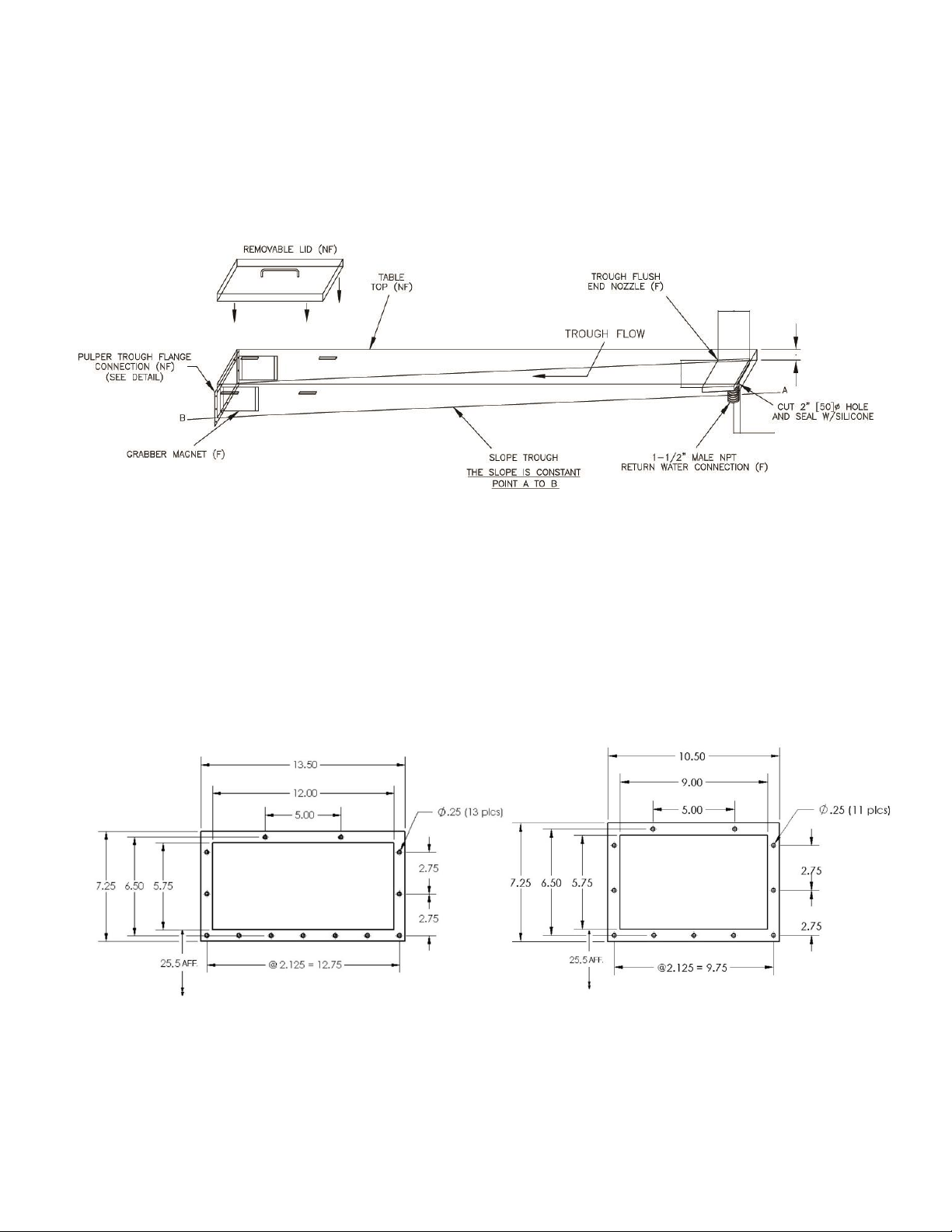
MOUNTING OF THE GRABBER MAGNETS:
Preferred: Locate per detail below and weld into place.
Optional: Drill four 7/32” diameter holes into the trough as shown below. Seal the
heads of the provided screws with silicone and attach the magnet.
RECOMMENDED POSITION OF THE GRABBER MAGNETS
MOUNTING DETAIL OF TROUGH
12” TROUGH DETAIL 9” TROUGH DETAIL
Holes in Pulper Trough Connection to be Drilled in the Field not done by the FACTORY

19
PLUMBING INSTALLATION
1. All freshwater lines and drain lines not supplied by Somat®.
2. Pipe sizes to be in accordance with Somat recommendations.
3. Trough return water piping to be Type L Copper piping
(PVC Piping NOT Acceptable)
4. All fittings must be pressure rated drainage type.
5. Keep drains accessible to unit. Do not install drains under Somat equipment.
6. No external strain to be exerted on Somat equipment.
7. Protect all Somat equipment and piping from freezing and condensation.
8. All piping to be in accordance with state and local plumbing codes.
9. F” = furnished by Somat / “NF” = not furnished by Somat.
FRESH WATER:
*NOTE: Check local codes regarding the proper backflow prevention devices to be
installed.
1. Bring a 1/2" cold water line for the Pulper, to the pre-piped freshwater assembly.
(See enclosed diagram and Installation Drawings)
2. Bring a 1/2" hot water line to the pre-piped freshwater assembly on the
Hydra-Extractor (see enclosed diagram and Installation Drawing).

20
HYDRA-EXTRACTOR®OVERFLOW AND PULPER DRAIN:
1. Install 1-1/2" pipe from the Hydra-Extractor®overflow to floor drain (do not reduce).
2. Install 2" pipe from the Pulper drain to floor drain (do not reduce).
RETURN PIPING FOR UNITS WITH A TRAY FEED ONLY:
1. Install one side of the provided tubing over to the return water elbow on the feed tray
and the other side onto the pump return water assembly (if not already factory
installed)
2. Install the provided hose clamps at each connection.
RETURN PIPING FOR UNITS WITH A TROUGH:
Pipe from the return pump to the supplied trough end flush nozzle and silver saver
connections as well as to the optional trough nozzles as shown in the trough detail on
the Installation Drawing using the provided throttling gate valves.
This manual suits for next models
5
Table of contents
Other Somat Industrial Equipment manuals


