BN Thermic MD3 Series User manual

Thank you for purchasing a BN Thermic product. Manufactured to a high standard, this product will, if used according to these instructions and
properly maintained, give you years of trouble free performance.
1. SAFETY INSTRUCTIONS
1.1 ELECTRICAL SAFETY
❑
WARNING!
It is the responsibility of the owner and the operator to read, understand and comply with the following:
You must check all electrical products, before use, to ensure that they are safe. You must inspect power cables, plugs, sockets and any
other connectors for wear or damage. You must ensure that the risk of electric shock is minimised by the installation of appropriate
safety devices. A Residual Current Circuit Breaker (RCCB) should be incorporated in the main distribution board. If in any doubt consult a
qualified electrician. You must also read and understand the following instructions concerning electrical safety.
1.1.1 The Health & Safety at Work Act 1974 makes owners of electrical appliances responsible for the safe condition of those appliances and the
safety of the appliance operators. If in any doubt about electrical safety, contact a qualified electrician.
1.1.2 Ensure that the insulation of all the cables on the appliance is safe before connecting it to the power supply.
1.1.3 Ensure that the cables are always protected against short circuit and overload.
1.1.4 Installation should always be carried out by a qualified electrician in accordance with current electrical regulation, protected by a suitably rated
isolator and fuse or mcb.
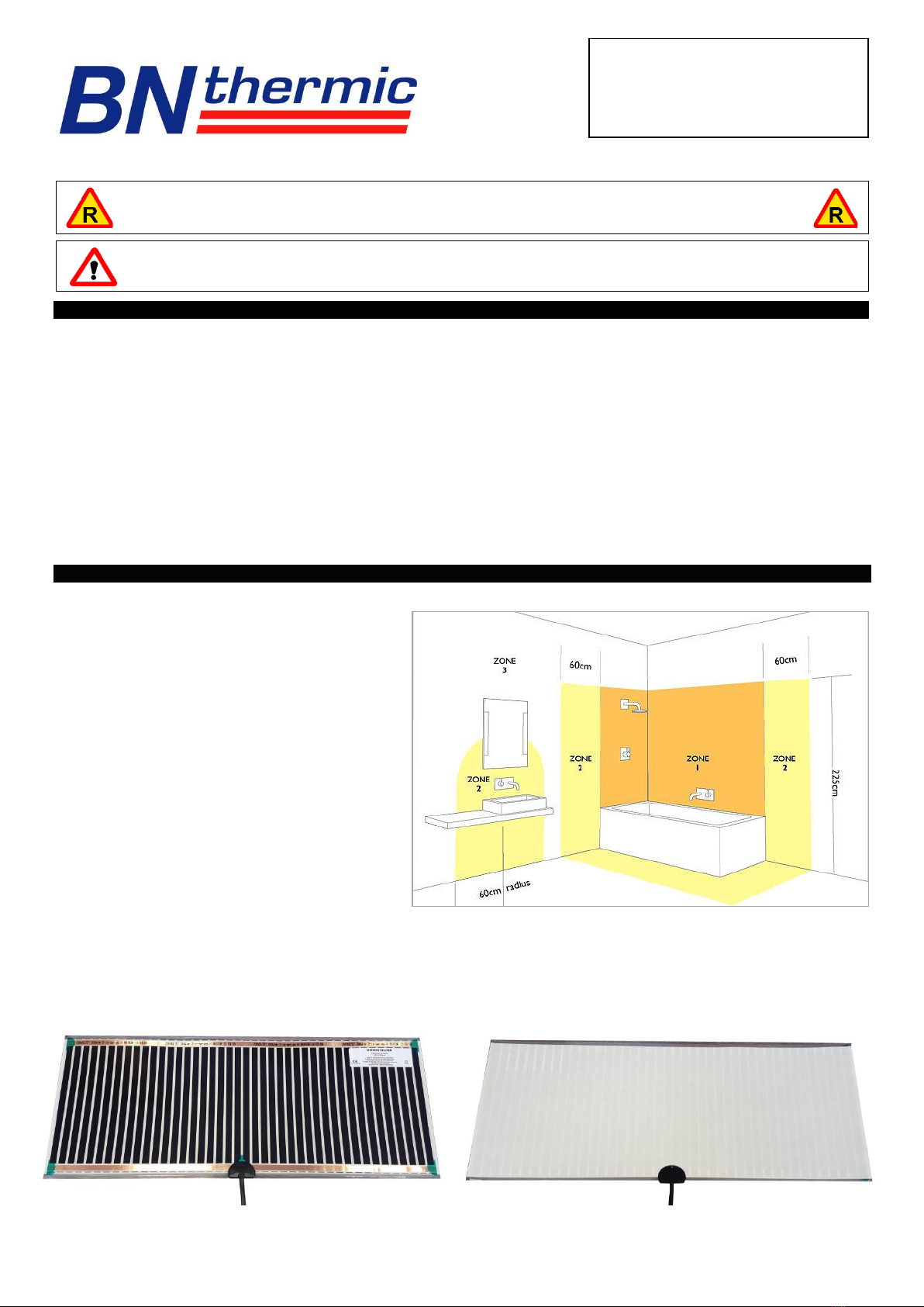
1.1.5 This Mirror must not be installed in a Zone1 area of any room (see Zone drawing below).
2. INSTALLATION
THESE INSTRUCTIONS SHOULD BE FOLLOWED TOGETHER WITH MIRROR MANUFACTURER’S INSTALLATION INSTRUCTIONS
This demister is designed to be used safely in Zone 2 or 3 of a
wet room (see drawing to the right).
2.1.1 The demister is best connected to a switched lighting
circuit, so that it is activated whenthe light is turned on.
2.1.2 The demister can also be wired to a separate On / Off
switch but this switch must be suitable for the area in
which it is to be used and placed in a position that it
cannot be touched by a person standing or sitting in
the bath / shower.
2.1.2 Stationary appliances without a means of all pole
disconnection from the supply must have a disconnect
device incorporated into the fixed wiring circuit.
2.1.3 The wiring regulations also require a double pole RCD
to be installed for all fixed current using appliances in
zones 2 & 3 in a bathroom.
2.1.4 The wires in the mains cable are double insulated and
coloured in accordance with the following code:-
BROWN:- LIVE BLUE:- NEUTRAL
2.1.5 Wiring must be covered and inaccessible in compliance with relevant safety standards.
2.1.6 All metal frames surrounding the mirror must be earthed and comply with current wiring regulations.
2.1.7 If the mirror has been supplied with a metal foil anti-shatter film then this film must be connected to earth due to a possibility of a small
capacitance effect.
2.1.8 The demister is supplied with 1.0m of double insulated cable and cannot be replaced, when a longer cable is required, a suitable junction box
and the correct cable must be used.
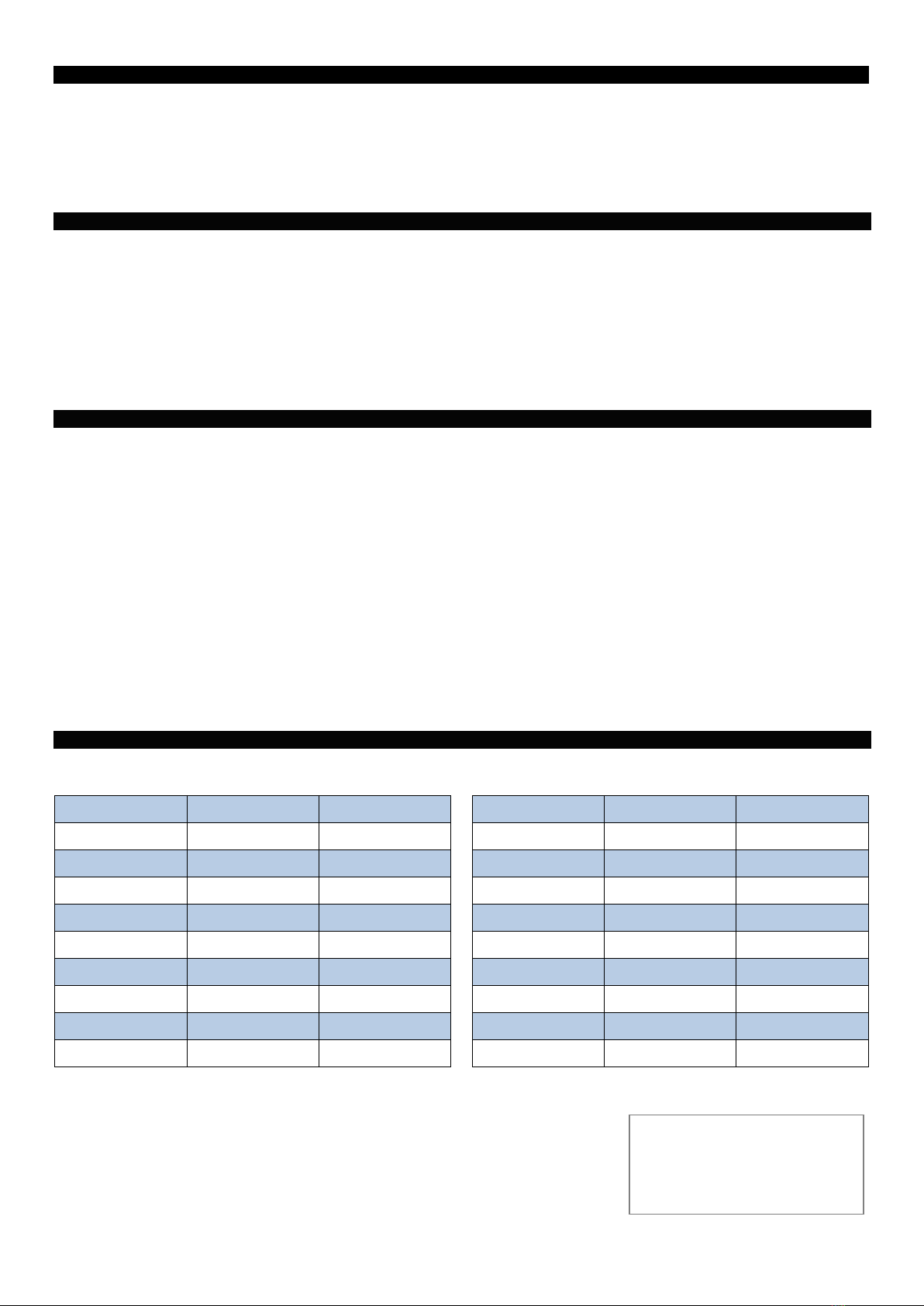
Back View Self Adhesive Side
To be placed facing wall To be placed on the back of the mirror
INSTRUCTIONS FOR:-
MIRROR DEMISTERS
MD3/5/7 Series
REGISTER: PLEASE REGISTER THIS PRODUCT ONLINE TO ACTIVATE YOUR GUARANTEE AT
www.bnthermic.co.uk
IMPORTANT: PLEASEREAD THESE INSTRUCTIONS, NOTETHE SAFE OPERATIONALREQUIREMENTS, WARNINGS, AND CAUTIONS.
USE THIS PRODUCT CORRECTLY, AND WITH CARE FOR THE PURPOSE FOR WHICH IT IS INTENDED. FAILURE TO DO SO MAY
CAUSE DAMAGE AND/OR PERSONAL INJURY AND WILL INVALIDATE THE WARRANTY.

3. MULITPLE DEMISTER PADS
Several pads may be fitted to a mirror to cover the whole area
3.1.1 Never cut any pad always use pads that are slightly smaller than the mirror.
3.1.2 If several pads are fitted to a single mirror they should be wired in parallel.
3.1.3 Pads must not overlap as this could cause hotspots and possible damage to the mirror.
3.1.4 Care must be taken to ensure that the power supply is sufficient to take the total load of all the pads.
4. IMPORTANT POINTS TO NOTE WHEN INSTALLING
TO AVOID DAMAGE TO THE MIRROR, AND IN COMMON WITH NORMAL PRACTICE, THE FOLLOWING POINTS MUST BE ADHERED TO:
4.1.1 Ensure wall is firm, flat, level and dry.
4.1.2 If the mirror has any holes or cut-outs the pad must not be located near the hole or cut-outs as the mirror could crack.
4.1.3 Mirror must be flat across its entire surface at all times to prevent it cracking.
4.1.4 Screws must not be over-tightened and must be adjusted evenly to ensure mirror is flat.
4.1.5 Never rest anything across the mirror surface which will prevent the heat dissipating fully.
4.1.6 We don’t recommend mounting behind irregular shaped mirrors.
5. ATTACHING TO MIRROR
The Mirror Demister should be mounted directly onto the mirror back.
5.1.1 Cut out a recess in the wall to accommodate the terminal moulding so the mirror will sit flush to the wall.
5.1.2 Mark the back of mirror to indicate where the heater is to be fitted.
5.1.3 Peel the protective release paper from the back of the heater.
5.1.4 Position one edge of the Mirror Demister onto the back of the mirror whilst holding the opposite edge away from the mirror.
5.1.5 Apply pressure evenly over the mirror heater surface as you gradually lower it onto the mirror.
5.1.6 Continue until it is completely flat on the mirror back with no air bubbles.
5.1.7 Fix mirror assembly to wall ensuring wall recess lines up with the terminal moulding.
5.1.8 If the heated mirror assembly is to be bonded to the wall, the adhesive must be solvent and acrylic free and should be applied over the
complete area including the demister pad to ensure that the mirror is securely held.
The Mirror Demister must not be cut or pierced as this will damage the insulation and render it unsafe.
Once installed the mirror demister must not be accessible.
Please be aware that as the ambient room temperature rises, so will the surface temperature of the mirror.
6. SPECIFICATION
Voltage:- 230V Nominal power rating:–200W/m² Double Insulated IP44 Rated
Model
Wattage
Dimensions
Model
Wattage
Dimensions
MD3-29
16W
300 x 290mm
MD5-97
92W
500 x 970mm
MD3-49
27W
300 x 490mm
MD5-125
119W
500 x 1250mm
MD3-73
40W
300 x 730mm
MD5-149
142W
500 x 1490mm
MD3-97
54W
300 x 970mm
MD7-29
38W
700 x 290mm
MD3-125
69W
300 x 1250mm
MD7-49
65W
700 x 490mm
MD3-149
83W
300 x 1490mm
MD7-73
98W
700 x 730mm
MD5-29
27W
500 x 290mm
MD7-97
131W
700 x 970mm
MD5-49
46W
500 x 490mm
MD7-125
169W
700 x 1250mm
MD5-73
69W
500 x 730mm
MD7-149
201W
700 x 1490mm
NOTE: It is our policy to continually improve products and as such we reserve the right to alter data, specifications and component parts without prior
notice.
IMPORTANT: No liability is accepted for incorrect use or installation of this product.
WARRANTY: Your BN Thermic product is guaranteed for one year from date of purchase. We will
repair or replace at our discretion any part found to be defective. We cannot assume any consequential
liability. This guarantee in no way prejudices your rights under common law and is offered as an addition
to consumer liability rights.
REGISTER:
Activate your warranty by registering online at www.bnthermic.co.uk and retain this
installation data for future reference.
MD3INSv01
BN Thermic Ltd,
34 Stephenson Way,
Crawley, RH10 1TN
Tel: +44 (0) 1293 547361
Email: sales@bnthermic.co.uk
Web: www.bnthermic.co.uk
This manual suits for next models
20