QUICK SETUP
Switching your marker on and off
The on/off button is located on a membrane pad on the rear of the frame. Push
the button with the power symbol ( ), when done correctly, your OLED will
display the MacDev logo and the marker will be set with the beam sensor sys-
tem on and ready to re. Turn your marker off by holding the power button down
until the OLED system goes blank.
Firing your marker
If a paintball is loaded in your marker, and the power is switched on, you may
re the marker by pulling the trigger. If a paintball is not loaded, then you need
to either load one, or read the section below on disabling the beam sensor.
Understanding the beam sensor
Your Cyborg is equipped with a visible light sensor to determine if a paintball is
correctly loaded. This system is used to prevent accidental ball breakage due to
misloaded paintballs. The OLED indicator on the side of your grip will show you
the status of the beam sensor:
Disabling the beam sensor
To disable the sensor (for dry ring), hold the scroll button on the membrane
pad ( )until the beam sensor disabled icon appears on the OLED display. You
can re-enable the beam sensor the same way.
Ball loaded Sensor disabled
No ball loaded Sensor fault
Power button
(for power on/off)
Scroll button
(for eyes on/off and pro-
gramming)
OLED Display
Membrane Pad
Battery meter
Sensor status
Cycle mode
Cycle speed (max)
Lock status
Game timer/
ROF meter
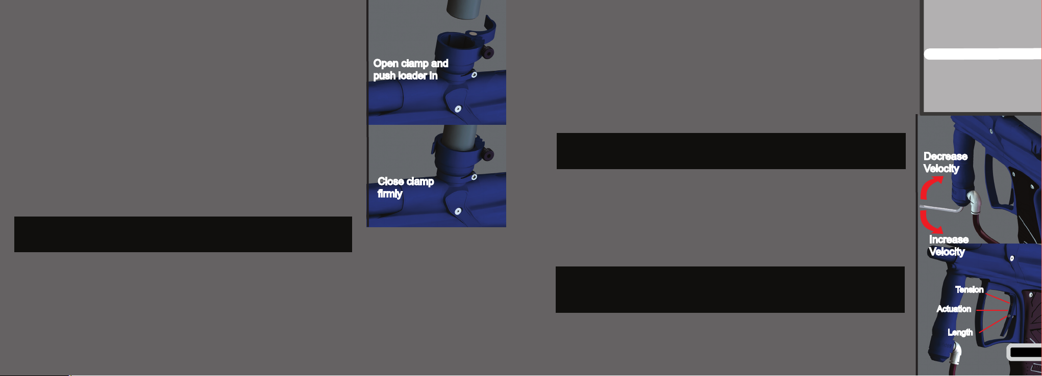
Installing a preset air system
Your Cyborg comes equipped with a high quality venting ASA (Air System Adap-
tor) that is designed for use with commercially available air/nitrogen systems.
The venting ASA included with your Cyborg uses a screw cap to turn the air
from your preset system on or off. Before installing your preset air system, you
must unscrew the ASA cap by approximately 3 turns (do not unscrew it further,
as the cap can come off completely).
Once this is done, carefully screw your air system into the ASA until it stops.
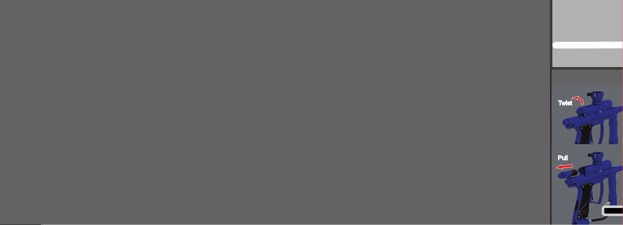
Turning the air on and off
To pressurise your marker, screw the ASA cap down until it stops. This will
depress the pin on the end of your air system and pressurise the marker
(provided you have sufcient air in your air system).
To depressurise your Cyborg, unscrew the ASA cap until you hear the air
being vented from the cap. Your air system is now turned off and safe to
remove.
WHEN SCREWING YOUR AIR SYSTEM INTO THE ASA, THE
THREADS SHOULD BE LOOSE. IF AT ANY POINT THEY BECOME
TIGHT, DO NOT FORCE THE THREADS, THIS MAY CAUSE DAMAGE
TO YOUR AIR SYSTEM OR YOUR MARKER!
NOTE: WHEN YOU UNSCREW THE ASA CAP, YOUR MARKER MAY
STORE ONE SHOT. POINT THE MARKER IN A SAFE DIRECTION AND
FIRE OFF THAT SHOT BEFORE ENTERING A SAFE AREA. 8
Contents
Know your Cyborg
Quick Setup
Using your Cyborg
Advanced Setup
Maintenance
Parts List
Troubleshooting
Turn air on
Turn air off