Bobrick MetroSeries 1550 User manual

Form No. 1550-69 r4/20/18 © 2018 Bobrick Washroom Equipment, Inc. Printed in U.S.A.
INSTALLATION INSTRUCTIONS
HIGH PRESSURE LAMINATE (HPL) TOILET PARTITIONS
1550 MetroSeriesTM and 1530 AccentSeriesTM
FLOOR
ANCHORED
OVERHEAD
BRACED
CEILING
HUNG
IMPORTANT:
Storage and Handling Information on last page.
For faster, easier installation, please review these
instructions thoroughly prior to installation.

Form No. 1550-69 r4/20/18 © 2018 Bobrick Washroom Equipment, Inc. Printed in U.S.A.
Page 2
PRE-INSTALLATION
A. Structural support in walls and floors is not furnished
by Bobrick. Confirm that adequate backing is present
in wall, ceiling and floors prior to installation.
B. This installation booklet must be used with the Bobrick
layout sheets.
C. You may verify hardware receipt by cross-referencing
the last page of the layout sheets against the box
contents.
INSTALLATION STEPS
1. Lay Out All Anchor Locations............................ Page 3
2. Install All Anchors ............................................. Page 4
3. Bracket and Screw Guide.................................. Page 5
4. Install Wall Brackets and Wall Posts.................. Page 6
5. Position Panels.................................................. Page 7
6. Install Stile-To-Panel Brackets........................... Page 7
7. Install Stiles and Set Door Openings ................ Page 8
8. Install Headrail (if applicable) ............................ Page 9
9. Install Hinges .................................................. Page 10
10. Install Door Hardware ..................................... Page 11
11. Install Shoes ................................................... Page 12
12. Finish And Cleanup......................................... Page 12
A. 1530 and 1550.64 option
uses stainless steel
hardware.
B. Organize components with
appropriate hardware.
C When calculating distances
to centerlines, all panels,
stiles, and doors are 1"
(25mm) thick.
D. Look for panel-to-stile
offsets indicated on the
layout sheets.
PREPARATION
RECOMMENDED TOOLS:
CAUTION: Be sure to use proper safety gear.
1. Chalk Line
2. Plumb-bob
3. Masking Tape (for laying out holes on
floors/walls/ceilings to be drilled)
4. Tape Measure and Pencils
5. Center Punch
6. Electric and/or
Battery-Powered Drill
7. Drill Bits
#19 (.166") M4.2
3/16" (4.7mm)
5/16" (8mm)
3/8" (9.5mm) for Concrete/Masonry
7/16" (11mm)
8. Screwdrivers/Screwdriver Bits
slotted and phillips, #1, #2 and #3
9. Pin-Head Torx Screw Driver – (to
install door hardware) – Supplied
by Bobrick
10. Shims
11. Adjustable Supports
1-1/2" to 12" (40–105mm)
12. Level
13. Wrench – 9/16" (14mm) open
end (2 reqd. for adjusting hex
nuts on anchors)
14. Hack Saw
15. Hammer
16 Safety Glasses

Form No. 1550-69 r4/20/18 © 2018 Bobrick Washroom Equipment, Inc. Printed in U.S.A. Page 3
Stile
Centerline
X
Y
1/2''
(13mm)
Panel Centerlines
C
LC
L
C
L
C
L
Stile
Centerline Panel
Centerline
XY
C
L
C
L
Panel
Centerline
X
Y
C
LStile
Centerline
C
L
X
Y
Panel
Centerline
C
LStile
Centerline
Y
X
X
Hex Nut
Lock Washer
Flat Washers
Hex Nut
A. Refer to Bobrick layout sheets for component locations on your specific application.
B. From back wall, measure and mark the location of the stile centerline. Stile centerline = 1/2" (13mm) + panel length + gaps
specified on layout sheets.
C. From side wall and center of stile location, measure dimensions for floor or ceiling anchors according to layout sheet. Refer
to the drilling tables below for center-to-center distances between anchors. For example: Overhead-Braced stiles centerline
of floor anchor from edge of stile is 1" (25mm); dimension on 3" (8cm) stile is 1-1/2" (38mm).
LAYOUT EXAMPLES
Fig. 1e: Detail of Overhead-
Braced Stile
NOTE: 16", 18", 20", 24" (41, 51, 46, 61cm) stiles have 2 leveling bars. Use the 2 outside slots
for the 2 anchors.
LAY OUT ALL ANCHOR LOCATIONSSTEP 1
Fig. 1f: Detail of Floor-Anchored or Ceiling-Hung Stile
X Dim. = Stile Edge to Centerline of Mounting Hole. Y Dim. = Centerline-to-Centerline of Mounting Hole.
Fig. 1a: Floor-Anchored or Ceiling-Hung
Front-Entry Corner Layout.
Fig. 1b: Overhead-Braced
Alcove Closed Layout.
Fig. 1d: Floor-Anchored or Ceiling-Hung
Alcove Closed Layout. Outswing Door.
Fig. 1c: Floor-Anchored or Ceiling-Hung
Alcove Closed Layout. Inswing Door.
NOTE: The center stile is perpendicular to panel.
NOTE: The stiles are in-line with panel. NOTE: The center stile is perpendicular to panel.
LEGEND: Obtain Dimension from Bobrick Layout Sheet.
Floor Anchored Stile
Drilling Table
Overhead-Braced Series — Standard & .64 Option Floor-Anchored Series & Ceiling-Hung Stiles Ceiling-Hung Series & .63 Option
Stile Size
(width)
No. of
Holes
X
Dim.
Y
Dim.
Stile Size
(width)
No. of
Holes
X
Dim.
Y
Dim.
Stile Size
(width)
No. of
Holes
X
Dim.
Y
Dim.
3" (76mm) 1 1-1/2" (38mm) - 3" (76mm) 1 1-1/2" (38mm) - 3" (76mm) 1 1-1/2" (38mm) -
4" (102mm) 2 1" (25mm) 2" (50mm) 4" (102mm) 1 2" (50mm) - 4" (102mm) 2 5/8" (16mm) 2-3/4" (70mm)
5" (125mm) 2 1" (25mm) 3" (75mm) 5" (125mm) 2 1-1/8" (30mm) 2-3/4" (70mm) 5" (125mm) 2 5/8" (16mm) 3-3/4" (95mm)
6" (152mm) 2 1" (25mm) 4" (102mm) 6" (152mm) 2 5/8" (16mm) 4-3/4" (121mm) 6" (152mm) 2 5/8" (16mm) 4-3/4" (121mm)
7" (178mm) 2 1" (25mm) 5" (127mm) 7" (178mm) 2 5/8" (16mm) 5-3/4" (146mm) 7" (178mm) 2 5/8" (16mm) 5-3/4" (146mm)
8" (200mm) 2 1" (25mm) 6" (152mm) 8" (200mm) 2 5/8" (16mm) 6-3/4" (172mm) 8" (200mm) 2 5/8" (16mm) 6-3/4" (172mm)
10" (254mm) 2 1" (25mm) 8" (200mm) 10" (254mm) 2 5/8" (16mm)) 8-3/4" (222mm) 10" (254mm) 2 5/8" (16mm) 8-3/4" (222mm)
12" (305mm) 2 1" (25mm) 10" (254mm) 12" (305mm) 2 5/8" (16mm) 10-3/4" (273mm) 12" (305mm) 2 5/8" (16mm) 10-3/4" (273mm)
16" (406mm) 2 1" (25mm) 14" (355mm) 16" (406mm) 2 5/8" (16mm) 14-3/4" (375mm) 16" (406mm) 2 5/8" (16mm) 14-3/4" (375mm)
18" (457mm) 2 1" (25mm) 16" (406mm) 18" (457mm) 2 5/8" (16mm) 16-3/4" (426mm) 18" (457mm) 2 5/8" (16mm) 16-3/4" (426mm)
20" (508mm) 2 1" (25mm) 18" (455mm) 20" (508mm) 2 5/8" (16mm) 18-3/4" (475mm) 20" (508mm) 2 5/8" (16mm) 18-3/4" (475mm)
24" (610mm) 2 1" (25mm) 22" (560mm) 24" (610mm) 2 5/8" (16mm) 22-3/4" (578mm) 24" (610mm) 2 5/8" (16mm) 22-3/4" (578mm)
Ceiling-Hung Stile

Form No. 1550-69 r4/20/18 © 2018 Bobrick Washroom Equipment, Inc. Printed in U.S.A.
Page 4
Finished
Ceiling
Hex Nut
Split Lock Washer
Bevel Washer
Hex Nut
Structural
Beam
Spacer
Flat Shoe Retainer
Hex Nuts
Flat Washers
Split Lock Washer
Leveling Bar
Threaded Rod
Hex Nut
1'' Ref.
(25mm)
or as
Required
Floor
L-Bracket
#14 x 1-3/4"
(6.4 x 45mm)
St. Stl.
Sheet-Metal
Screw
#14-16
Plastic Anchor
Shoe
Retainer
Flat Washer
Hex Nut
Hex Nut
Flat Shoe Retainer
Wedge Anchor
2-1/8'' to 2-1/4''
(54 to 60mm)
1-5/8'' to 1-3/4''
(41 to 44mm)
Flat Washer
Leveling Bar
Install when
stile is placed
on anchor bolts.
Flat Washer
Hex Nut
Lock Washer
1'' Ref.
(25mm)
or as
Required
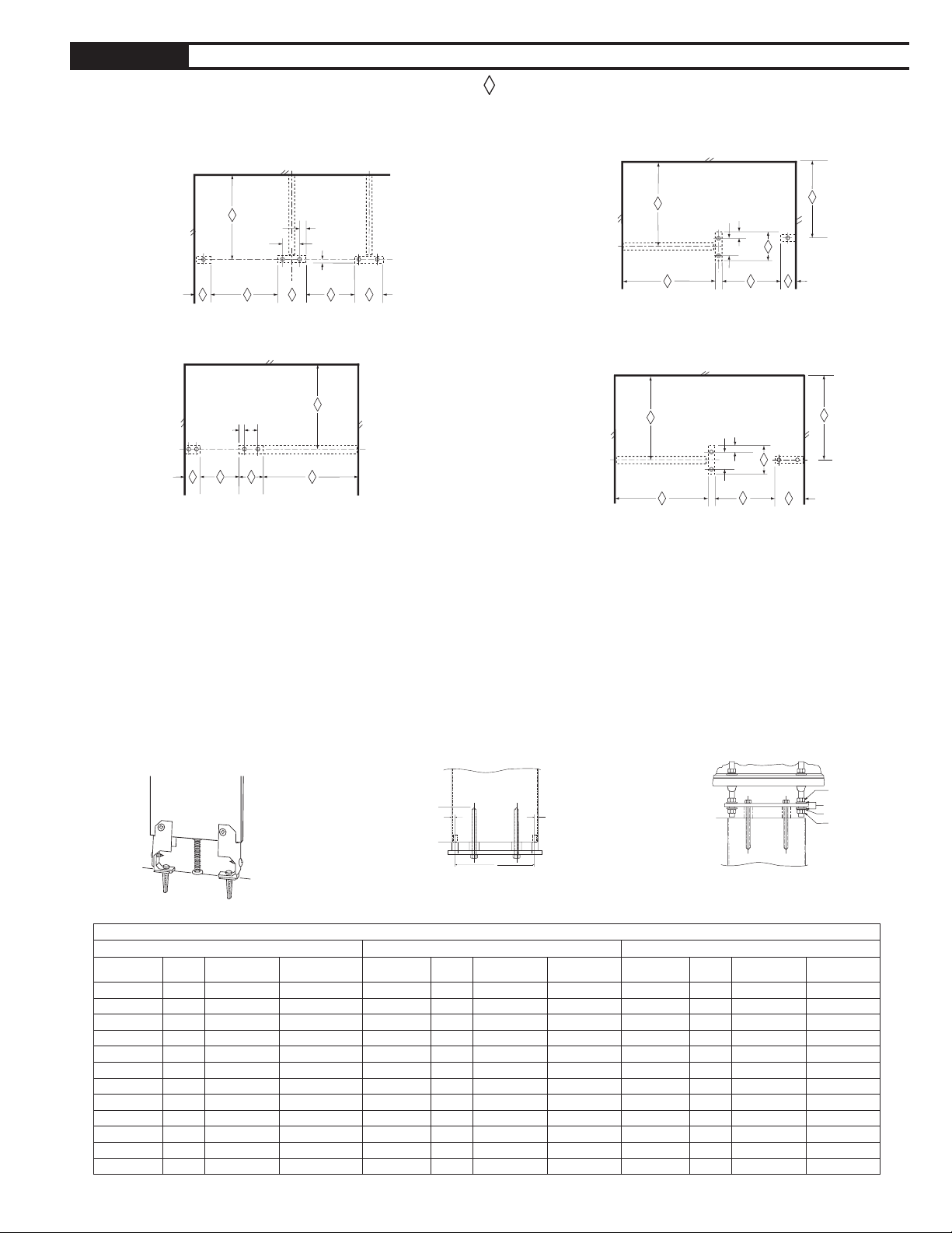
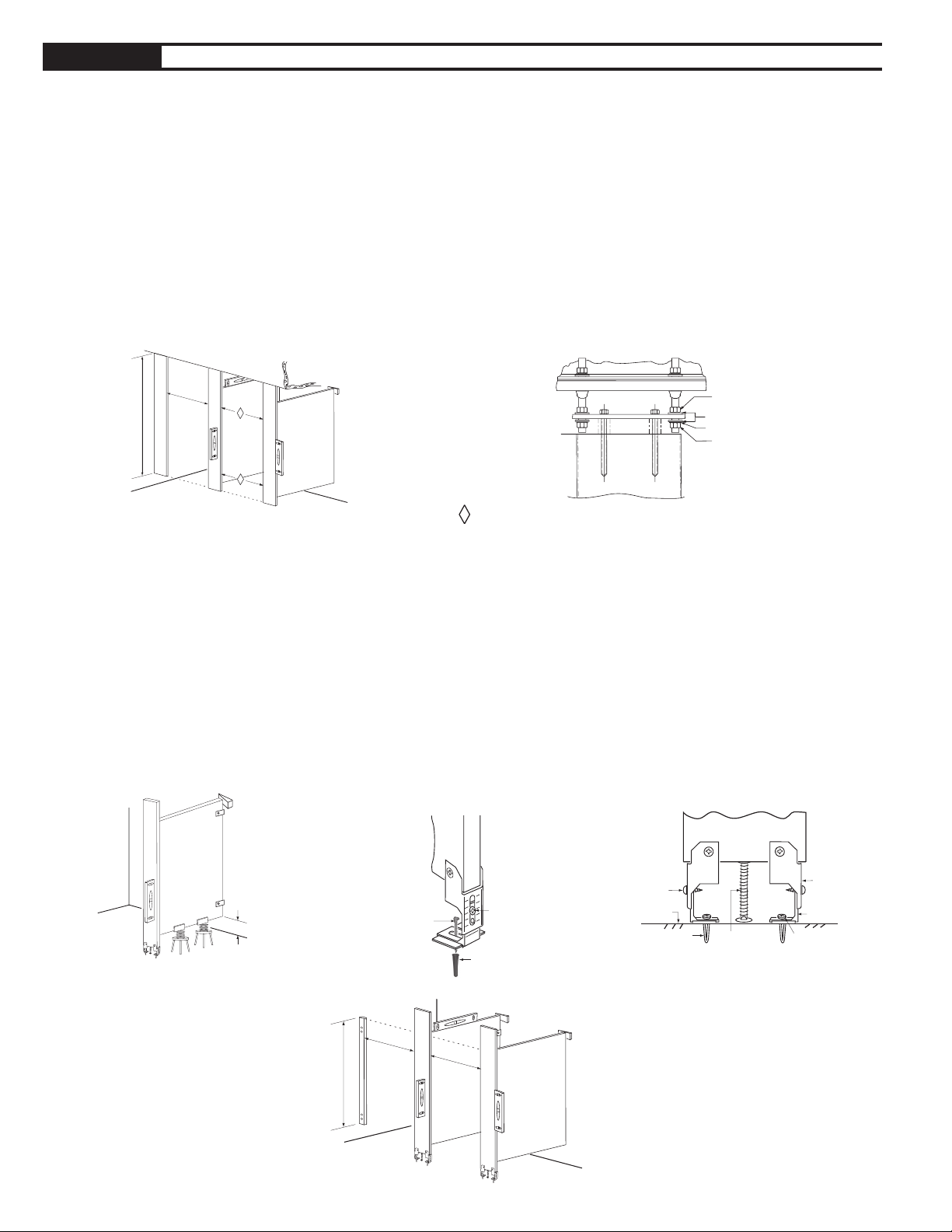
FLOOR ANCHORS. Standard
A. Drill 3/8" (9.5mm) diameter hole to 2" (50mm) minimum
depth. Remove all loose material from holes.
B. Insert expansion shield (threaded side down) with
threaded rod into mounting hole. Extra flat washers are
supplied. Place as many flat washers as necessary onto
rod to ensure shoe retainer is placed above finished floor
surface. Install and tighten a hex nut above washer(s) and
shoe retainer, tightening and expanding anchor to secure
to floor. Make sure when tightening bolt that shoe retainer
is positioned properly to accept shoe (see Fig. 2b for
proper shoe retainer position).
C. Add a second hex nut, then a flat washer.
D. Set aside the third hex nut, flat washer, and the lock
washer. Install when stile is placed on anchor bolts.
E. Repeat process for each floor anchor.
NOTE: Wood-floor anchors are available upon request.
CEILING ANCHORS.
NOTE: Ceiling anchors are to be installed before finished
ceiling is applied. All structural framing is to be furnished by
others. For Bobrick recommendations, refer to Bobrick Form
No. TB-32.
A. Drill 7/16" (11mm) diameter hole through structural
beam. Insert threaded rod through hole in beam. Rod
is furnished standard 6" (150mm) length. Longer rods
should be purchased locally if required.
B. Drop a bevel washer and lock washer over rod. Screw on
one hex nut.
C. Install second hex nut against bottom of beam and
tighten.
D. Install spacer, shoe retainer, flat washer, and a third
hex nut. Make sure shoe retainer is in proper position
to accept shoe (see Fig. 2c for proper shoe retainer
position).
E. Install remaining flat washers (2), lock washer (1), and
hex nuts (2), as shown in Fig. 2c.
F. Repeat process for each ceiling anchor.
Fig. 2b: Detail of Floor Anchor.
Fig. 2c: Detail of Ceiling Anchor.
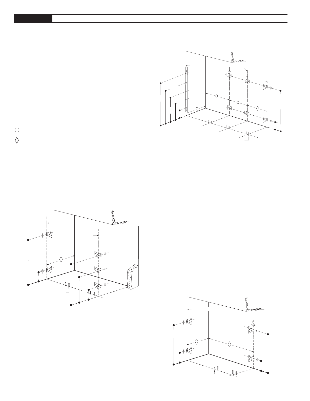
INSTALL ALL ANCHORSSTEP 2
OVERHEAD BRACED FLOOR ANCHORS
A. Based on stile size locate centerline of floor L-brackets
from Drilling Table. (See page 3).
B. Drill 5/16" (8mm) diameter hole to 1-3/4" (45mm)
minimum depth. Remove all loose material from holes.
C. Install plastic anchors into holes.
D. Place one shoe retainer bracket at each hole location.
E. Place floor L-bracket on top of and inside each shoe
retainer.
F. Install #14 x 1-3/4" (M6.4 x 45mm) floor screws to retain
bottom floor L-brackets and shoe retainers. Do NOT
tighten screws. Screws should be loose enough to adjust
the floor L-brackets.
G Using the stile as a measurement tool, adjust the floor
L-brackets to fit inside the stile brackets. Mark locations.
H. Remove stile and tighten floor screws securely.
NOTE: Wood-floor anchors are available upon request. To
install drill 3/16" pilot hole in the floor and install using #14 x
1-3/4" (M6.3 x 45mm) screws.
Fig. 2a: Detail of Overhead-Braced
Floor Anchor.

Form No. 1550-69 r4/20/18 © 2018 Bobrick Washroom Equipment, Inc. Printed in U.S.A. Page 5
F-bracket
Qty. (2)
Y-bracket
Qty. (3)
U-bracket
Qty. (3)
L-bracket
Qty. (3)
Y-bracket
Qty. (2)
Y-bracket
Qty. (3)
L-bracket
Qty. (3)
Y-bracket
Qty. (2)
Y-bracket
Qty. (3)
1000974
Y-bracket
Qty. (3)
L-bracket
Qty. (3)
Y-bracket
Qty. (3)
F-bracket
Qty. (2)
L-bracket
Qty. (3)
Y-bracket
Qty. (2)
Y-bracket
Qty. (3)
L-bracket
Qty. (3)
#1000356
Internal Panel to Stile
#1000974
External Panel or Stile
to Wall or Panel
BRACKETS AND SCREW GUIDE
#1000353
Internal Panel to Wall
F-bracket U-bracket Y-bracket
#1000351
External Panel to Stile
L-bracket
Overhead-Braced Alcove Open Layout
and Adjoining Front-Entry Stall.Overhead-Braced Alcove Closed Layout.
Front-Entry Corner Layout.
NOTE: Adequate wall backing is required. High-quality drill bit is suggested for drilling into steel-core stiles.
EXAMPLE BRACKET APPLICATIONS.
#1002495
#12 x 2" (M5.5 x 50mm)
Wall Screws
#1002500
#12 x 3/4" (M5.5 x 19mm)
Panel/Stile Screws
• #19 (.166) x 3/4" (4.2 x 19mm)
• For attachment of brackets to panels.
• Do not through-drill.
• 3/16" x 3/4" (4.7 x 19mm)
• For attachment of U-brackets, L-brackets
or Y-brackets to steel-core stiles only.
• Do not through-drill.
• #19 (.166) x 2" (4.2 x 50mm)
• For attachment of all wall brackets
to stud backing.
Pilot Hole Sizes—
NOTE: The stile is
perpendicular to
panel. No hardware
is exposed on the
outside of stall.
Floor-Anchored or Ceiling-Hung
Alcove Closed Layout.
NOTE:
U- and F-brackets
are used on
internal panels
only, where there
is an adjoining
stall to conceal the
hardware.
NOTE: The stile is
in-line with panel.
No hardware is
exposed on the
outside of stall.

Form No. 1550-69 r4/20/18 © 2018 Bobrick Washroom Equipment, Inc. Printed in U.S.A.
Page 6
67-1/2''
(171cm)
41''
(104cm)
64''
(163cm)
Panel
Centerlines
Floor Anchors
14-3/4''
(37cm)
18''
(46cm)
Wall Post
54-1/2''
(138cm)
27-1/2''
(69cm)
64''
(163cm)
18''
(46cm)
Panel
Centerline
64''
(163cm)
43''
(109cm)
Floor Anchors 18''
(46cm)
Stile
Centerline
64''
(163cm)
18''
(46cm)
Panel Centerline
64''
(163cm)
Floor Anchors
Panel Centerline
18''
(46cm)
A. Measure and mark the locations of centerlines for all
the stiles and panels on walls.
B. Using the wall brackets as templates, measure
and mark the location of all mounting holes, plumb
according to dimensions shown in illustrations (Fig.
3a, 3b, 3c).
C. Use #19 (.166) drill bit (4.2mm) for 2" (50mm) deep
pilot holes into adequate wall backing.
D. Secure wall brackets with 1002495 screws.
INSTALL WALL BRACKETS AND WALL POSTS
STEP 3
Fig. 3a: Front-Entry Corner Layout with
Wall Post.
Fig. 3b: Overhead-Braced Alcove Closed
Layout.
Fig. 3c: Floor-Anchored or Ceiling-Hung
Alcove Open Layout.
These mounting points require wall backing.
Obtain Dimension from Bobrick Layout Sheet.
WALL POST #1002250
A. Determine the location and hole of the 1" x 1-1/2"
(25 x 40mm) stainless steel wall post being installed.
Outside edge of wall post to be in-line with outside
edge of keeping stile. The wall must have adequate
backing at mounting location to support door hung in
place.
B. Install wall post at given height and fasten, plumb in
both directions to wall with (5) wall screws provided.
Install (2) post end caps and (5) mounting hole plugs.
C. Attach door with through bolts provided as you install
door(s) on pages 13.

Form No. 1550-69 r4/20/18 © 2018 Bobrick Washroom Equipment, Inc. Printed in U.S.A. Page 7
Panel Centerline
6''
(15cm)
69''
(175cm)
29''
(74cm)
52''
(132cm)
Panel Centerline
82-5/16''
(209cm)
18''
(46cm)
64''
(163cm)
41''
(104cm)
64''
(163cm)
43''
(109cm)
18''
(46cm)
64''
(163cm)
18''
(46cm)
12''
(31cm)
1. Place adjustable supports in position for each panel to
hold them 12" (305mm) above the floor.
2. Place panels on the supports and into their respective
wall brackets. Do not secure panels to wall brackets at
this time.
Fig. 4: Panel and Adjustable Supports.
Fig. 5a: Floor-Anchored or
Ceiling-Hung Bracket
Placement.
Fig. 5b: Overhead-Braced
Bracket Placement.
CAUTION: Panel centerline is not
always on the stile centerline. Refer
to Bobrick Layout Sheets for panel
offsets.
A. Measure and mark the centerlines
for three (3) U- or L-brackets per
stile.
B. Using U- or L-bracket as a template,
mark the location of all mounting
holes.
C. For U- or L-brackets attached to
steel-core stiles, use a high-quality
drill bit 3/16'' (4.7mm) for 3/4"
(19mm) deep pilot holes.
D. Caution: Do not drill through the
stile. For L-brackets attached to the
edge of stile, use a #19 (.166) drill
bit (4.2mm) for 3/4" (19mm) deep
pilot holes.
E. Secure U- or L-brackets
with 1002500 screws.
For
Internal
Panel
For
External
Panel
STEP 4 POSITION PANELS
INSTALL STILE-TO-PANEL BRACKETS
STEP 5
For
Internal
Panel
For
External
Alcove
In-Line
Panel
(Refer to
examples
on page 5.)
(Refer to
examples
on page 5.)

Form No. 1550-69 r4/20/18 © 2018 Bobrick Washroom Equipment, Inc. Printed in U.S.A.
Page 8
Stile Bracket
Floor L-Bracket
#14 x 5/8''
(6.4 x 16mm)
St. Stl.
Sheet-Metal
Screw
#14 x 1-3/4''
(6.4 x 45mm)
St. Stl. Sheet-Metal Screw
Leveling Bolt
#14-16
Plastic Anchor
Finish Face
of Floor
#14 x 5/8''
(6.4 x 16mm)
St. Stl.
Sheet-Metal
Screw
#14 x 1-3/4''
(6.4 x 45mm)
St. Stl. Sheet-Metal
Screw
#14-16
Plastic Anchor
12''
(305mmn)
Hex Nut
Flat Washers
Lock Washer
Hex Nuts
Threaded Rod
Flat Shoe Retainer
Expansion Shield
Leveling
Bar
Step A
Flat Washer
Hex Nut
Lock Washer
Flat Washers
Hex Nut
Hex Nut
Lock Washer
Flat Washers
Hex Nut
A. Place the stiles onto the threaded rods of anchors. Add a flat washer, lock washer, and a third hex nut to each
threaded rod of floor anchors (these should already be in place on ceiling anchors—refer back to Fig. 2b). Do not
tighten hex nuts at this time.
B. Ensure edge of panel is touching screw heads in brackets on stiles. Using brackets as templates, drill 3/16" (.187) x
5/8" (6.4 x 16mm) pilot holes in panel.
C. Fasten brackets to panels with #14 x 5/8" (6.4 x 16mm) screws or 1002500 for stainless steel option.
D. Use level to plumb stiles. Place shims between panels and wall.
E. Set door openings to be square, plumb and true per Bobrick Layout Sheets.
F. Tighten hex nuts on stile anchoring system.
G. Secure panels to wall brackets using #14 x 5/8" screws or 1002500 for stainless steel option.
INSTALL STILES AND SET DOOR OPENINGSSTEP 6
A. Install leveling bolt into stile.
B. While stile is laying flat, rotate leveling bolt so that overall stile dimension is 82-5/16" (209cm) from the head of the
leveling bolt to the top edge of stile.
Note all floor slopes and adjust stile heights accordingly.
C. Mount stile and install #14 x 5/8" (6.4 x 16mm) screws through the side of stile bracket into the floor L-bracket. Leave
screws loose. (Fig. 6d)
D. Level and plumb the panels. Using stile U-bracket as a template, drill 3/16" (5mm) pilot holes into the panel.
Special note: U-bracket panel hole should be a minimum of 1/2" (13mm) off edge of panel.
F. Fasten U and F-brackets to panels with #14 x 5/8" (6.4 x 16mm) screws or 1002500 for stainless steel option.
G. Level and plumb stile. Tighten stile bracket screws #14 x 5/8" into floor L-bracket.
Fig. 6a: Ceiling-Hung Installation Fig. 6b: Front View Ceiling-Hung Stile
Fig. 6c: Panel Installation
Floor-Anchored and Ceiling-Hung Series
Overhead-Braced Series
Fig. 6d: Front View
Overhead-Braced
Fig. 6e: Side View
Overhead-Braced
Obtain Dimension from Bobrick Layout Sheet.

Form No. 1550-69 r4/20/18 © 2018 Bobrick Washroom Equipment, Inc. Printed in U.S.A. Page 9
Stile Stile Panel
Front Headrail
Outswing Door
Return Headrail
*
End Cap
Stile
Stile
Panel
# 12 x 2''
St. Stl. Sheet-Metal
Screws
Stile
Stile
Panel
Return Headrail
Front Headrail
Headrail Bracket
Back Wall
# 12 x 7/16''
St. Stl.
Sheet-Metal
Screws
Wall
INSTALL HEADRAIL (IF APPLICABLE)
STEP 7
Fig. 7a: Alcove Configuration.
Fig. 7b: Headrail Installation Hardware.
Corner Configuration.
Back viewFront view
Fig. 7c: Detail of End Cap.
Note: Bobrick provides headrail in 84" (213cm) long
sections. Headrail seams must be located over stiles.
A. Measure wall-to-wall dimension less 1/4" (6mm). For
corner application, measure from wall to outside edge
of stile less 1/8" (3mm).
B. Place headrail over top of stiles.
C. Drill #19 (.166) x 3/4" (4.2 x 19mm) pilot holes through
interior sides of headrail into stiles. Fasten headrail to
stile using #12 x 7/16" (M5.5 x 10mm) screws.
D. For corner and alcove layouts, cut return headrail 1/8"
less than dimension from inner edge of headrail to the
back wall.
E. Using headrail L-bracket as a template, mark the
location for mounting holes in back of front headrail
and wall.
F. Drill #19 (.166) x 3/4" (4.2 x 19mm) pilot holes. Fasten
headrail L-bracket to stile using #12 x 7/16" (M5.5 x
10mm) screws.
G. Drill #19 (.166) x 2" (4.2 x 50mm) pilot holes in wall.
Fasten headrail L-bracket to wall using #12 x 2" (M5.5
x 50mm) screws.
H. Insert headrail return piece into headrail L-bracket.
Secure with #12 x 7/16" (M5.5 x 10mm) screws.
I. For corner layouts, install end cap to finish open
headrail end.

Form No. 1550-69 r4/20/18 © 2018 Bobrick Washroom Equipment, Inc. Printed in U.S.A.
Page 10
Door Half
Bottom
Hinge
(No Cam)
Stile
Half
Top Hinge
(With Cam)
Cam
#1002156
#1002330
2 x “L”
Hinge Set
Right Hand
Inswing
or
Left Hand
Outswing
Left Hand
Inswing
or
Right Hand
Outswing
#1002331
2 x “J”
Hinge Set
#1002330
2 x “L”
Hinge Set
Cam
Adjustment Points
Stile
Half
Door Half
#1002331
2 x “J”
Hinge Set
Upper Hinge
Lower Hinge
Stile
Stile
Door
Cam
INSTALL HINGES
STEP 8
Fig. 8a: Hinge Configuration. Fig. 8b: Right-Hand Inswing Door.
Hinge
A. Using hinge diagram at left, identify the upper and lower hinge set for right hand or left hand installation. Locate
#1002156 cam for upper hinge.
B. Separate hinge sets and fasten the 2 halves that have plastic bushings with “teeth” and cam alignment tabs onto stile
using driver and (1/4-20" x 34") screws. Refer to diagram to ensure “J” and “L” halves are located properly.
C. Fasten remaining upper hinge half to door.
D. Insert hinge pin and #1002156 plastic cam on upper stile hinge half.
E. Lift door and position onto upper stile hinge half. Door should be hanging securely on upper hinge.
F. Insert remaining hinge pin in lower door and hinge half and mount to door.
To Increase or Decrease Opening of Door.
A. Alignment tabs have been formed into the cam and plastic hinge bushing.
B. Lift door to limit of upward travel (approximately 1/2"). While door is lifted, raise cam above bottom bushing and rotate
so alignment tabs meet.
C. To set door in open position, rotate cam toward door opening direction.
D. To set door in closed position, rotate cam toward door closing direction.
E. Door may not function properly if cam and bushing tabs are not aligned properly.
F. When the cam has been set at the desired free resting position, “either closed or open” the top of the affixed
components will be aligned
Tip – Industry tolerance in the hardware will sometimes allow fine alignment to some partition components.
These fine adjustments may be performed by loosening the hardware screws and adjusting the components
the direction needed and retightening the screws.
Remove clothes hook, latch, keepers, brass inserts, latch track.

Form No. 1550-69 r4/20/18 © 2018 Bobrick Washroom Equipment, Inc. Printed in U.S.A. Page 11
Door
Latch
Keeper
Door C
L
Panel C
L
Stile
5/16''
(8mm)
Max.
7/8''
(22mm)
1-7/8''
(45mm)
3/4''
(19mm)
28-1/6''
(710mm)
3/16''
(4mm)
1-1/2''
Latch
Keeper &
Door Stop
Door C
L
PanelC
L
Stile
2-1/2''
2''
1-3/8''
(35mm)
1-7/8''
(50mm)
5/16''
(8mm)
28-1/6''
(715mm)
1-7/8''
(50mm)
Keeper
Latch
INSTALL DOOR HARDWARESTEP 9
Inswing
A. Mount latch and keepers as shown (Fig. 9f) using
1002500 (#12 x 3/4") screws.
Perpendicular Keeping Stile: Mount latch as shown
(Fig. 9g) using 1002500 (#12 x 3/4") screws for the
latch and keeper. Using keeper as template, place
keepers as shown overhanging edge of stile, to line
up with latch slide. Mark location of mounting holes.
Secure keeper using 1002500 (#12 x 3/4").
NOTE: To ensure emergency access, locate the
keepers so that the latch slide is no more than 5/16"
(8mm) into the keeper slot as shown. (Fig. 9f).
B. Mount robe hook (Fig. 9h) using 102500 (#12 x 3/4")
screws.
C. Mount inswing door bumper (Fig. 9h) to panel or door
at location that prevents door from hitting panel on the
inswing.
Fig. 9f: Mounting Location of Latch,
Keeper with Emergency Access.
Fig. 9h: Robe Hook and Bumper.
Fig. 9g: Perpendicular Stile Mounting
Location of Latch Keeper.
Fig. 9i: Mounting Location of Latch and
Keeper with Emergency Access.
Outswing
A. Mount latches and keepers as shown (Fig. 9f, 9i) using
screws 1002500 (#12 x 3/4").
NOTE: To ensure *emergency access, locate the
keeper so the latch slide is seated no more than 5/16"
(7mm) from the top of keeper (See Fig. 9i).
B. On outswing door, install the handle on outside of
door opposite the latch. Using the door handle as a
template on the outside of door, mark location for top
hole in handle 31-5/8" (803mm) up from the bottom
edge of door. Mark location for bottom hole in handle.
Drill two (2) 3/16" (5mm) diameter holes of door
using #8-32 x 1-14" one way screws provided. For
accessible compartments, latch must also be installed
on the interior.
C. Mount robe hook 1002500 (#12 x 3/4") screws.
D. Mount outswing door bumper using 1002500 (#12 x
3/4") at location that prevents door from hitting surface
on the outswing.

Form No. 1550-69 r4/20/18 © 2018 Bobrick Washroom Equipment, Inc. Printed in U.S.A.
Page 12
1'' Thick Stile
3/16'' Wide Flange
for 1'' Thick Stile
Close
Retaining Screw
Fasten When Closed
Shoe
Trap Bottom Flange
Under Shoe Retainer Shoe Retainer
1'' Thick Stile
3/16'' Wide Flange
for 1'' Thick Stile
Close
Shoe Retainer
Flat Washer at
Floor or Ceiling
Retaining Screw
Fasten When Closed
2. Close
to Engage Retainer
1. Push on Retaining Clip
to Engage with Hole
This End to Wall
Anchor Bolt,
Nuts & Washers
Shoe
Trap Bottom Flange
Under Shoe Retainer
1'' Thick Stile
3/16'' Wide Flange
for 1'' Thick Stile
Shoe Retainer
Flat Washer at
Floor or Ceiling
Anchor Bolt,
Nuts & Washers
Shoe
Trap Bottom Flange
Under Shoe Retainer
A. Locate proper width shoe for stile.
B. Confirm shoe retainer (#1002413 for Overhead-Braced Series (Fig. 10) or #1002186 for Floor-Anchored or Ceiling-
Hung Series (Fig. 10) is installed on anchor bolt next to flat washer closest to floor or ceiling. For anchor assembly
detail, reference diagram on Page 4.
C. Shoes accommodate 1" thick or 3/4" thick stiles. For 1" thick stiles, orient shoe with 3/16" wide flange return against
faces and edge of stile.
D. Standard Stile Installation - See Fig. 10
Open end of shoe and slide onto bottom of stile, trapping bottom flange under shoe retainer. Close open end of shoe,
overlapping so holes are aligned. Install flat head retaining screw through double thickness of material to close shoe.
E. Remove protective covering and wipe shoe clean.
INSTALL SHOESSTEP 10
Fig. 10: Standard Stile Installation. (Overhead-Braced Anchor Shown)
A. Remove any exposed labels from the components of toilet compartments.
B. Clean surfaces as needed. CAUTION: Do not use cleaners containing acid on Bobrick toilet compartments.
For example, tile cleaners containing acid may attack the stainless steel hardware.
For Bobrick recommendations, refer to Bobrick Form Nos. TB-21 and TB-60.
STEP 11 FINISH AND CLEANUP
REPLACEMENT SHOE GUIDE
Stile Width Bobrick Part Number Stile Width Bobrick Part Number
3" 1002175 10" 1002179
4" 1002176 12" 1002180
5" 1002184 16" 1002181
6" 1002177 18" 1002196
7" 1002197 20" 1002182
8" 1002178 24" 1002183

Form No. 1550-69 r4/20/18 © 2018 Bobrick Washroom Equipment, Inc. Printed in U.S.A.

Form No. 1550-69 r4/20/18 © 2018 Bobrick Washroom Equipment, Inc. Printed in U.S.A.
In the U.S.A.: BOBRICK WASHROOM EQUIPMENT, INC.
Los Angeles: 6901 Tujunga Ave., North Hollywood, CA 91605-6213: Tel: (818) 982-9600, Fax: (818) 503-1102
New York: 200 Commerce Drive, Clifton Park, NY 12065-1350; Tel: (518) 877-7444, Fax: (518) 877-5029,
In Canada: BOBRICK WASHROOM EQUIPMENT COMPANY
45 Rolark Drive, Scarborough, Ontario M1R 3B1
Eastern Canada Tel: (877) 423-6555, Fax: 877-423-8555; Western Canada Tel: ( 877) 423-6444, Fax: 877-423-8444,
or e-mail customerservice@bobrick.com
This manual suits for next models
1
Table of contents
Other Bobrick Toilet manuals