FLO AT
C U P
LO C K
RIN G
REFILL TU B E
FILL
VA LVE
SH A N K
W A SH ER
FLO AT
C U P
LO C K
RIN G
REFILL TU BE
FILL
VA LVE
SH A N K
W A SH ER
Fill Valve Installation Instruction
Replacement Installation
5 - 5
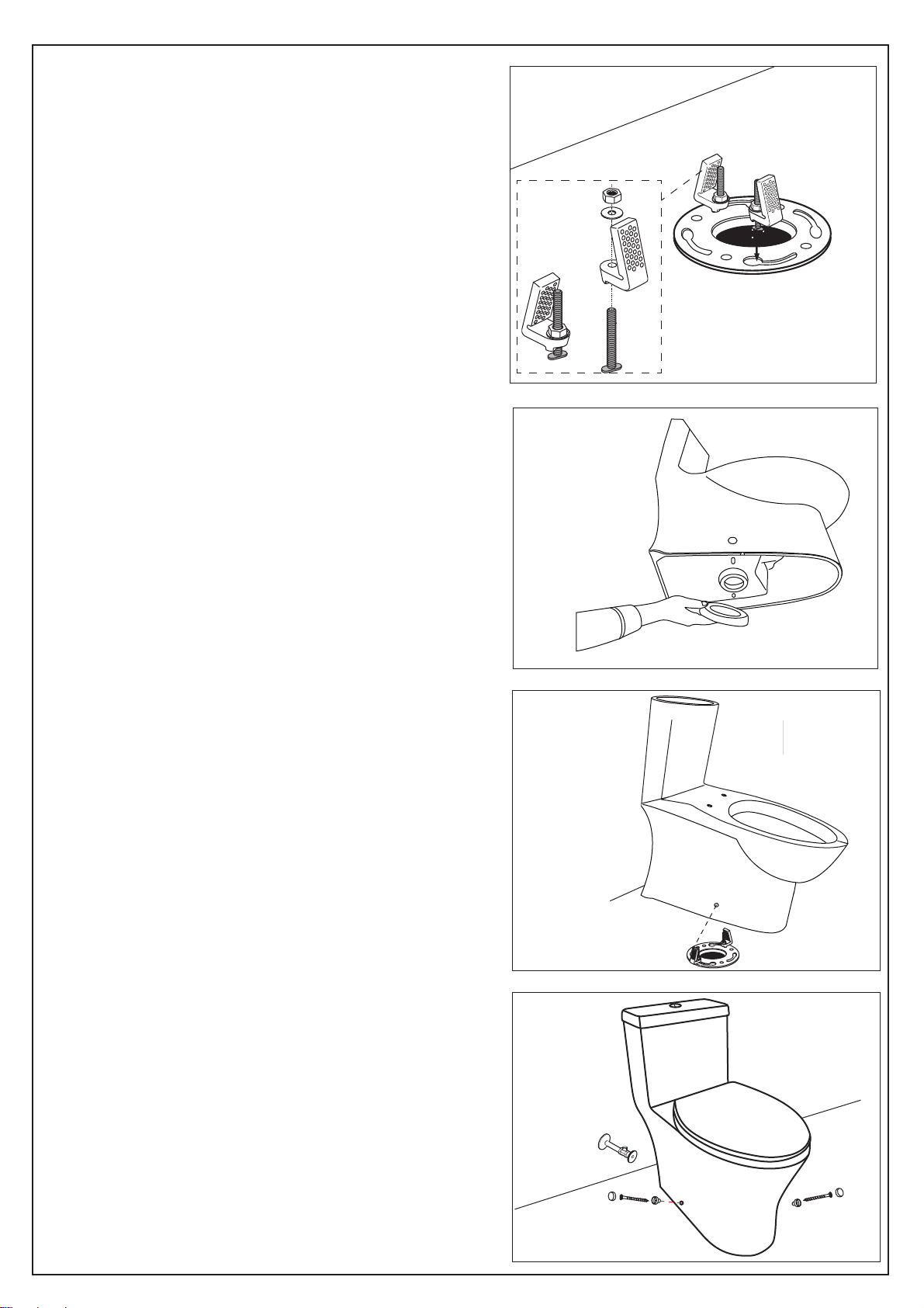
1) Shut off the water supply. Flush the toilet and
remove any remaining water from the tank.
Remove the old fill valve.
2) Install new fill valve by sliding the threaded
portion of the shaft through the hole in the
bottom of tank.
3) Thread mounting nut onto exposed shaft under
the tank/bowl and tighten nut.
WARNING! Do not over-tighten.
4) Connect the water supply.
FLO AT
C U P
LO C K
RIN G
FILL
VA LVE
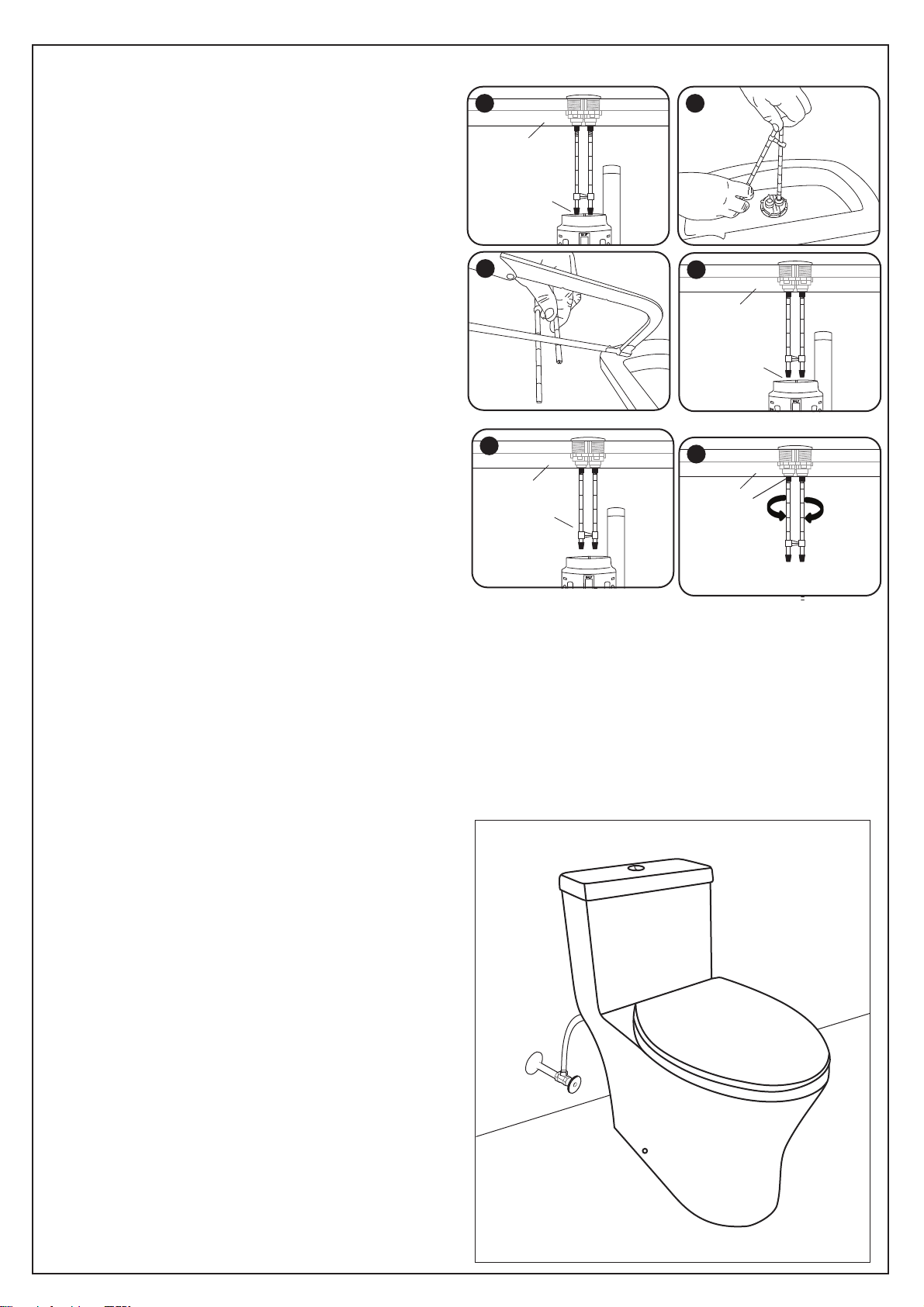
Water Level Adjustment
1) Loosen the lock ring (see figure 3)
Pull up the valve and set it to the desired water level, then turn it clockwise until the valve snaps into the locked position.
2) Turn on the water supply.
Figure 1 Figure 2 Figure 3
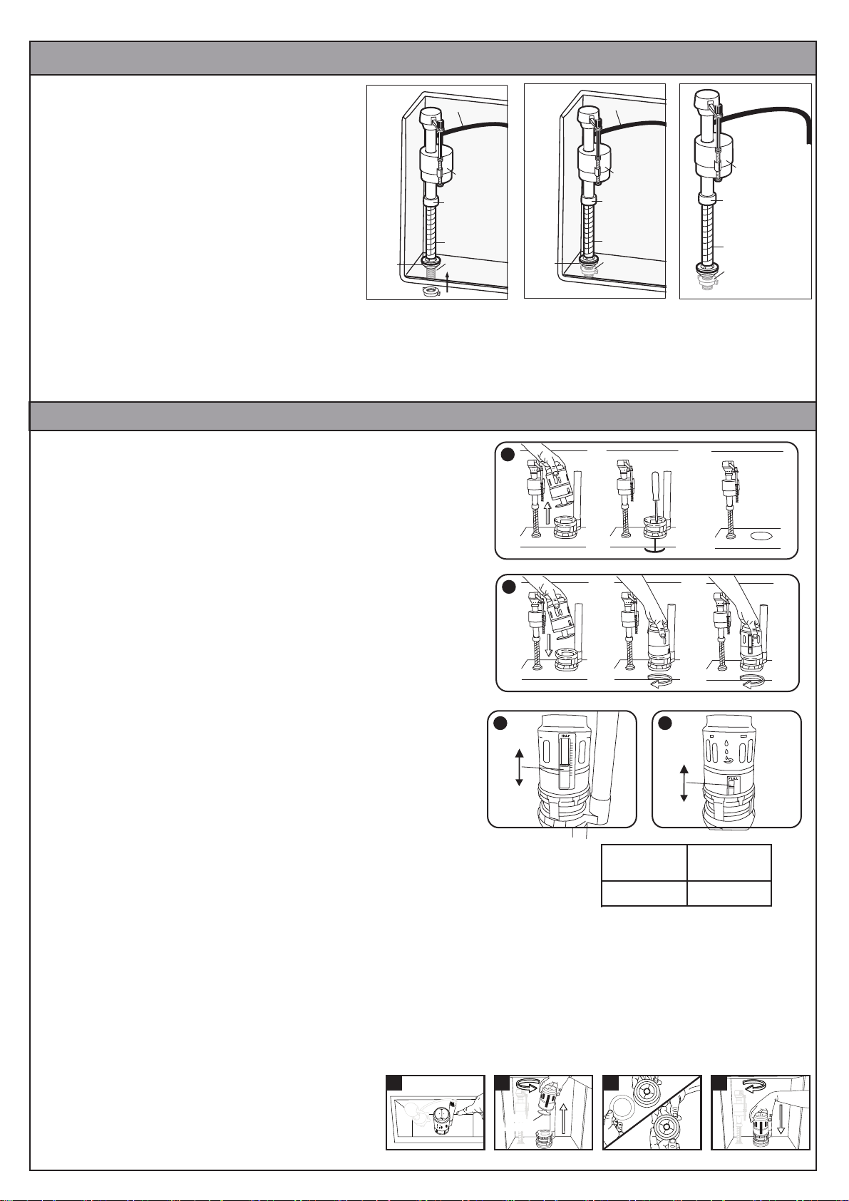
Flush Valve Installation Instruction
A
B
1) Turn off water supply and flush the toilet.
2) Remove the tank lid and place it upside down on a clean surface.
3) Note the orientation of the flush valve for reassembly.
4) Screw down the flush valve body.
5) With a screw driver to loosen the screw on the flush base, remove the
flush base.
6) Install the new flush valve base into the pan.
7) Install the flush valve body back on the base.
8) Rotate the flush valve so that the white button is on the left and the
blue button is on the right.
9) Carefully install the tank lid back on the tank.
10) Flush the toilet several times using each push button to verify
proper operation. Check for leak
Replacement Installation
FULL
C
HALF
B
HALF Flush
Window
#6
FULL Flush
Window
#3
A. Consult the included chart to find your toilet model
and the settings for the full and half flush settings.
B. Adjust the half flush float. Locate the BLUE float
and scale marked at the top with the word "HALF".
While pressing firmly on the gray tab, slide the float
up or down until it reaches the setting in chart.
C. Adjust the full flush window. Locate the GRAY
adjustment and scale marked at the top with the word
"FULL". Slide the gray tab up or down until it reaches
the setting in chart.
Water Level Adjustment
D
C
SEAL
LOCATION
SEAL
LOCATION
B
A
1)Note position of half and full flush paddles on the top of the flush valve (Figure A).
2)Holding the valve body, rotate the valve until it is possible to remove the valve body from the shank (Figure B).
3)Holding the edge of the silicone seal, pull the seal and peel away from the sealing piston - discard the old seal.
4)Place the inside edge of the replacement seal against the inside edge of the sealing piston (Figure C).
5)Holding the edge of the replacement seal, pull until the seal installs onto the piston.
6)Inspect the seal to make sure the entire inner edge of the seal is
making contact with the inner edge of the sealing piston.
7)Replace the valve body in the shank, and rotate the
valve until the position of the half and full flush
paddles are returned to their original position
(Figure D). Replace the lid, turn on the water supply.
Replacing the Master Seal
C