BobsCNC E3 User manual

Page 1
E3

Page 2
Table of Contents
Specicaons··································································································4
Safety First
Geng Started ·······························································································5
Required Tools
Good Ideas
For More Informaon
E3 Hardware Parts Guide ················································································6
- ························································7-17
Wood Components (included with the kit)
Required Hardware (included with the kit)
Illustrated Steps
···································································18-37
Wood Components (included with the kit)
Required Hardware (included with the kit)
Illustrated Steps
·········································································38-42
Wood Components (included with the kit)
Required Hardware (included with the kit)
Illustrated Steps
········································································43-55
Wood Components (included with the kit)
Required Hardware (included with the kit)
Illustrated Steps
···············································56-60
·····································································61-64
Wood Components (included with the kit)
Required Hardware (included with the kit)
Illustrated Steps
································································65-69
Wood Components (included with the kit)
Required Hardware (included with the kit)
Illustrated Steps

Page 3
··························································································70-74
Wood Components (included with the kit)
Required Hardware (included with the kit)
Illustrated Steps
Installing the Spoilboard ·················································································75-76
Inial Setup ···································································································76-79
Tips to Keep Your Controller from being Damaged ·········································80-81
GRBL and Universal G Code Sender Soware··················································82
Quick Start Guide····························································································83-84
Appendix ···································································································85-90
Warranty and Return Policy ··································································85
Miscellaneous Parts List········································································86
Frame Parts Diagram ············································································87
Gantry Parts Diagram············································································88
Y Carriage Parts Diagram·······································································89
Z Parts Diagram·····················································································90

Page 4
Specifications
The E3 CNC Engraver has the following features:
• Rigid laser cut frame.
• Fully supported rail system with SG20U bearings.
• GT2 belt drive on X and Y axis.
• 5/16-18 coupler nut on the Z axis.
• Home switches on all axes.
• MDF Spoilboard with 1/4-20 threaded inserts.
The assembled footprint:
Length: 24.8" (630 mm)
Width: 25.2" (640 mm)
Height: 18.9" (480 mm)
Assembled Weight:
25 lbs.
Cung Area:
X: 17.7" (450 mm)
Y: 15.3" (390 mm)
Z: 3.3" (85 mm)
your
Routers have a high voltage power supply. Router bits spin at 30,000 rpm
and have cung edges that are hazardous. The operator should understand
these hazards and take appropriate safety precauons before operang the
Router.

Page 5
• Two ½” end wrenches to ghten Z Bearing nuts.
• A pair of long nose pliers to hold the nuts.
• Diagonal Cuers or sharp knife to trim nylon es.
• Calipers or measuring tape to measure part placement.
• Small standard screwdriver to connect electronics.
• Small Phillips screwdriver to mount home switches and stepper motors.
• Medium Phillips screwdriver to build the main components.
• Sand paper to remove laser marks on the faces.
• M4 Star Driver for DeWalt disassembly.
• LOCTITE 243 thread lock (ngernail polish can be used as a substute).
To operate the E3 CNC Router you will need:
7/16” & 5/8” wrench to change router bits.
Computer with control soware for GRBL.
Build material.
1/8” or 1/4” Router bits.
Dry lubricaon (e.g., graphite, Teon or silicon spray).
Tools you may need for the electronic setup include:
Mulmeter to correctly connect the power supply and stepper motors. A mulmeter is also a good tool to have for
general electronic trouble shoong.
Getting Started
• We recommend using a large at, clean working surface for assembling your E3.
• All screws (unless noted) should be installed snug, then rotated one 1 to 2 1/2
turns.
• Light sanding of the wood surfaces will clean up the marks made by the laser.
• Painng or applying stain with a clear coat will give added protecon to the wood
*For More Information: Click on the Links
*Look for Good Ideas

Page 6
Short Zip Tie
Long Zip Tie
M5
Washer
5/16”
-

Page 7
-
-
-
-
-
-
5/16”

Page 8

Page 9

Page 10
“” -

Page 11

Page 12

Page 13
.
be careful not to remove
spindle sha
’
-

Page 14

Page 15

Page 16

Page 17

Page 18
-
-
-
5/16”

Page 19
1” -
-

Page 20
Other manuals for E3
3
Table of contents
Popular Power Tools manuals by other brands

AEG
AEG OF 2050 E Original instructions
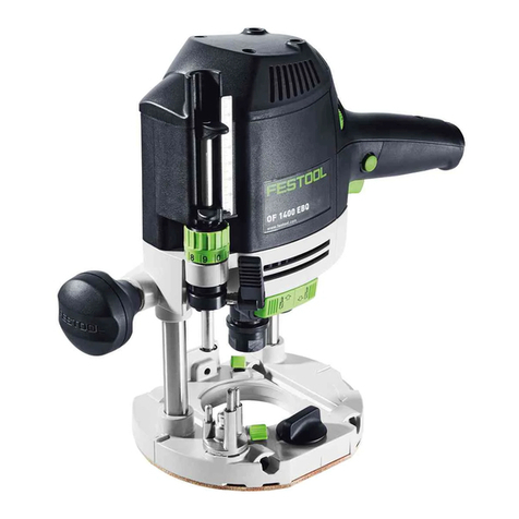
Festool
Festool OF 1400 EQ Original instructions

norbar
norbar EvoTorque ET-72-1000-110 Original instructions

Hitachi
Hitachi N 5008AC2 Handling instructions

Bosch
Bosch GSZ 160 Professional Original instruction

Allied
Allied HO-PAC 400B Safety, Operation, Maintenance and Parts
