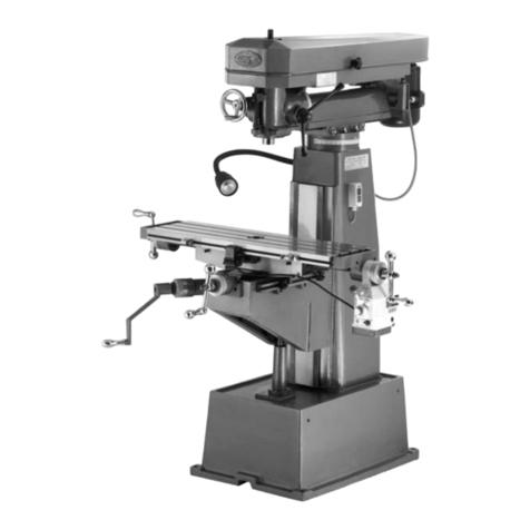
Avdel 7900 User manual

Instruction Manual
Instruktionshåndbog
Instruktionshandbok
Instruksjonsbok
Käyttöohje
07900-09080 model
Speed Fastening Applications
Broach Load Test Power Tool
0
0
20
40 60
80
100
1
2
34
5
6
7
lbf/in
2
bar
CALIBRATIONdue
07900-09080
07900-09080 model
Høyhastighetsnagling
Testverktøy for brotsjbelastning
07900-09080 modeller
Hurtignitningsapplikationer
Trykluftsværktøj til test af
rømmenålsbelastning
Malli 07900-09080
Pikamiittaus-kahteisiin
Vetokarojen Testaustyökalu
07900-09080 model
Höghastighetsnitning
Testverktyg för brotschbelastning


3
Contents
Safety Rules 4
Tool Specifications 5
Intent of Use 5
Putting into Service
Air Supply 6
Loading the Tool 6
Cursor 6
Nose Equipment 6
Operating Procedure 7
Air Pressure Graph vs Broach Load 8
Mandrel Life Table 9
Dansk 13
Svenska 23
Norsk 33
Suomi 43
Avdel policy is one of continuous product development and improvement and we reserve the right to change the specification of any product without prior notice.
Warranty
Avdel installation tools carry a 12 month warranty against defects caused by faulty
materials or workmanship, the warranty period commencing from the date of delivery
confirmed by invoice or delivery note.
The warranty applies to the user/purchaser when sold through an authorised outlet,
and only when used for the intended purpose. The warranty is invalidated if the
installation tool is not serviced, maintained and operated according to the instructions
contained in the Instruction and Service Manuals.
In the event of a defect or failure, and at its sole discretion, Avdel undertakes only to
repair or replace faulty components.
CONTENTS
English

4
1Do not use outside the design intent.
2Do not use equipment with this tool/machine other than that recommended and supplied by Avdel.
3Any modification undertaken by the customer to the tool/machine or any equipment supplied by Avdel or their representatives, shall be the
customer’s entire responsibility. Avdel will be pleased to advise upon any proposed modification.
4The tool/machine must be maintained in a safe working condition at all times and examined at regular intervals for damage and function
by trained competent personnel. Any dismantling procedure shall be undertaken only by personnel trained in Avdel procedures. Do not
dismantle this tool/machine without prior reference to the maintenance instructions. Please contact Avdel with your training requirements.
5The tool/machine shall at all times be operated in accordance with relevant Health and Safety legislation. In the U.K. the “Health and
Safety at Work etc. Act 1974” applies. Any question regarding the correct operation of the tool/machine and operator safety should be
directed to Avdel.
6The precautions to be observed when using this tool/machine must be explained by the customer to all operators.
7Always disconnect the airline from the tool/machine inlet before attempting to adjust, fit or remove a nose assembly.
8Do not operate a tool/machine that is directed towards any person(s).
9Always adopt a firm footing or a stable position before operating the tool/machine.
10 Ensure that vent holes do not become blocked or covered.
11 Do not operate the tool if it is not fitted with a complete nose assembly or swivel head unless specifically instructed otherwise.
12 When using the tool, the wearing of safety glasses is required both by the operator and others in the vicinity to protect against fastener
ejection, should a fastener be placed ‘in air’. We recommend wearing gloves if there are sharp edges or corners on the application.
13 Take care to avoid entanglement of loose clothes, ties, long hair, cleaning rags etc. in the moving parts of the tool which should be kept
dry and clean for best possible grip.
14 When carrying the tool from place to place keep hands away from the trigger/lever to avoid inadvertent start up.
15 The combination of fastener, mandrel, hole size and sheet thickness shall be in accordance with specifications set by Avdel.
16 The cylinder of the tool must be free to move without risk of hitting or trapping the operator.
This instruction manual must be read with particular attention to the following safety rules, by any person
operating this tool.
Safety Rules
IMPORTANT
While a small amount of wear and marking will naturally occur through normal and correct use of mandrels, they
must be regularly examined for excessive wear and marking, with particular attention to the head diameter, the tail
jaw gripping area of the shank or heavy pitting of the shank and any mandrel distortion. Mandrels which fail during
use could forcibly exit the tool. It is the customer's responsibility to ensure that mandrels are replaced before any
excessive levels or wear and always before the maximum recommended number of placings. Contact your Avdel
representative who will let you know what that figure is by measuring the broach load of your application with a
calibrated test tool. These tools can also be purchased under Part Number 07900-09080, supplied with all
necessary information for testing in this manual.

5
Specifications
TOOL SPECIFICATION
Air Pressure Maximum 7 bar
Free Air Volume Required @ 5.5 bar 1.72 litres
Noise Level Less than 70 dB(A)
Weight Without nose equipment 3.0 kg
Vibration Less than 2.5 m/s2
This particular test tool is to be used solely with Avdel®speed fasteners supplied by Avdel. The precise list of fasteners appears in the
mandrel life table page 9. The tool is supplied without any nose equipment as it is fundamental that this tool is used fitted with the exact same
nose equipment as that used on the placing tool you have selected to place your fasteners. Tools can be purchased under part number 07900-
09080 or you may contact your local Avdel representative to test your application.
The test tool can be used to define the ideal combination of tool/nose equipment/fastener for your application and in any case MUST be used
prior to the actual placing tool in order to define the broach load exerted on the mandrel when placing a fastener in the application. IT IS
ESSENTIAL TO ESTABLISH THE BROACH LOAD TO PREVENT OVER-USAGE OF MANDRELS AND RISK BREAKAGE AND INJURY.
The intensity of the broach load will vary with the level of interference between the diameters of the fastener, of the mandrel head and of the
hole in the application as well as with the thickness of the application. SPEED FASTENING DEMANDS RIGOROUS OBSERVATION OF
RECOMMENDATIONS laid down in fastener technical data sheets and in the selection process of nose equipment laid down in instruction
manuals.
When putting the test tool into operation, its gauge will display the air pressure at which a particular fastener will place in a specific
application with defined nose equipment.
The graph on page 8, will allow you to convert that air pressure (bars) into a broach load (Newtons) which in turn can be
translated, using the table page 9, into a maximum safe number of placings for that series of fasteners with the exact same
nose equipment you will use with your placing tool AND in random samples of your actual application.
INTENT OF USE
English

6
AIR SUPPLY
This tool operates with compressed air at a maximum pressure of 7 bar. We recommend that you temporarily make use of the air supply set
up for your actual placing tool with precautions as described in the instruction manual for your placing tool.
CURSOR
IMPORTANT
It is essential that the correct nose equipment is fitted to the tool to ensure both effective placing of the
fastener and SAFE operation of the tool.
NOSE EQUIPMENT
LOADING THE TOOL
IMPORTANT
It is essential to check that the cursor orientation before attempting to operate the tool.
The procedure for loading the tool with fasteners and for fitting the nose equipment to the tool are integral. Refer to the instruction manual for
your specific placing tool EXCEPT FOR 1.6MM (1/16”) AVLUG®WHICH SHOULD BE LOADED ONE AT A TIME PER TEST AS THE TEST TOOL
CANNOT EXACTLY EMULATE THE 07176 PLACING TOOL USED FOR PLACING THIS FASTENER.
To avoid complete dismantling of the tool check the orientation of
the cursor before fitting the nose equipment to the tool. If fitted
incorrectly, the cursor will not allow feeding of the fasteners. When
fitted the correct way round, the cursor will easily slide out of the
barrel when a mandrel is pushed into its centre then pulled back.
To reverse the orientation of the cursor, refer to the instruction
manual for your particular placing tool. The sprung loaded, slightly
concave, end of the cursor should point towards the front of the
tool as shown right.
NOSE
JAWS
TOOL
BARREL
CURSOR
SPRING
LOADED END
Fit the same mandrel, follower spring and nose jaws as you intend to fit on the tool which you have selected to place your fasteners following
the ‘tool loading’ instructions in the manual for that tool.
Putting into Service

7
IMPORTANT
The test tool MUST be returned to Avdel at minimum every 6 months for re-calibration.
A new manual with an updated air pressure versus broach load graph will be supplied in English and in the
official language of your country if EC regulations apply.
NO MAINTENANCE WHATSOEVER MAY BE CARRIED OUT ON THIS TOOL BY ANYONE OTHER THAN
SPECIFICALLY TRAINED AND DESIGNATED AVDEL PERSONNEL. FOLLOWING MAINTENANCE, THE TOOL
MUST BE RE-CALIBRATED PRIOR TO FURTHER USE.
OPERATING PROCEDURE
READ THE SAFETY INSTRUCTIONS page 4 carefully.
•Connect the test tool to the air supply.
•Set the gauge on the test tool to zero actuating the trigger
to ensure a true reading.
•Fit the exact same nose equipment to the test tool as you
intend to use on the tool you will be using to place the
fasteners in your application and as recommended in the
instruction manual for your specific tool. Note that when
testing 1/16” Avlug®fasteners NO POD must be used. A
single fastener must be fed at a time. To fit the nose
equipment, follow the ‘Loading the tool’ procedure in the
instruction manual for your placing tool.
•Switch on tail jaws by operating slider valve.
•Offer the protruding fastener into the application applying a
little pressure to ensure that the fastener head rests against
the application (This is crucial to obtain a true reading).
•Hold the trigger in and SLOWLY raise the air supply pressure until the fastener places. Keeping the trigger held, read the air pressure off
the gauge before releasing the trigger.
•The mandrel is pulled through the fastener which is formed into the application.
•Remove the application. The next fastener will automatically be presented through the front nose jaws, ready for placing.
•The highest of at least 10 readings should be used.
•As the test tool was calibrated, the graph on page 8 will convert the air pressure reading in bars into a broach load in newtons.
TO CONVERT THE BROACH LOAD INTO A MAXIMUM NUMBER OF FASTENER PLACINGS PER MANDREL
•Locate your broach load reading on the scale at the top of the table on page 9 and on the left-hand side, find the line with your fastener
(name and size).
•The maximum recommended number of fastener placings with one mandrel will be shown where they intersect. THIS NUMBER OF
PLACINGS MUST NOT BE EXCEEDED. In case of doubt contact Avdel for advice.
Putting into Service English

8
Air Pressure Graph vs Broach Load

9
Mandrel Life Table
MAXIMUM NUMBER OF FASTENER PLACINGS PER MANDREL MAX. LOAD AT
Fastener Tool Broach Load (lbf / N) 5000 PLACINGS
(for which the 100 / 110 / 120 / 130 / 140 / 150 / 160 / 170 / 180 / 190 / 200 / 225 / 250 / 275 / 300 / 325 / 350 / 375 / 400 / 450 / 500 / 550 / 600/ 650 / 700 / 750 / 800 / 850 / 900 /
mandrel is used) 445 489 538 582 627 672 717 762 806 851 896 1008 1120 1232 1344 1456 1568 1680 1792 2016 2240 2464 2688 2912 3136 3360 3584 3808 4032 lbsf N
1/16 Avlug 26000 20000 13000 XXXXXX XXXXXXXXXXX XXX X X X XXXX127565
3/32 Briv 45700 36300 32500 28800 25100 23400 16000 10200 XXXXXXXXXXXX X XX XXXXXXX177787
2.8mm Rivscrew 50000 30500 25100 20900 16200 14600 13200 10400 8710 7240 6110 XXXXXXXXX X XX XXXXXXX214952
3mm Rivscrew 50000 30500 25100 20900 16200 14600 13200 10400 8710 7240 6110 XXXXXXXXX XXX XXXXXXX3141397
2.5mm Avtronic 50000 50000 50000 49000 38900 35100 32400 29500 26600 23700 20400 11200 XXXXXXXX X XX X X X X X X X 2411072
# 3/32 Avlug 50000 50000 50000 50000 43200 37200 33900 31600 28800 26300 23200 14500 XXXXXXXX X XX X X X X X X X 2441085
3/32 Avlug 50000 50000 50000 50000 50000 40300 35900 33300 30900 28200 25700 18000 6920 XXXXXXX X XX X X X X X X X 2581148
3/32 Chobert 50000 42600 33500 28200 23400 20400 17400 15000 12900 10800 9300 6400 XXXXXXXX XXX X X X X X X X 2421077
3/32 Grovit 50000 42600 33500 28200 23400 20400 17400 15000 12900 10800 9300 6400 XXXXXXXX X XX XXXXXXX2421077
2.5mm Avsert 50000 42600 33500 28200 23400 20400 17400 15000 12900 10800 9300 6400 XXXXXXXX X XX XXXXXXX2421077
4-40 UNC Avsert 50000 42600 33500 28200 23400 20400 17400 15000 12900 10800 9300 6400 XXXXXXXX X XX XXXXXXX2421077
1/8 Avlug --
50000 50000 50000 50000 48400 39800 35900 34500 30900 25700 19100 10800 XXXXXX XXX X X X X X X X 2911294
2.8mm Avtronic 50000 50000 50000 50000 50000 50000 50000 44200 38500 35500 33100 27900 21900 14600 XXXXXX XXX X X X X X X X 2951312
1/8 Chobert --
50000 50000 41700 35100 29500 26000 22600 20200 18000 12200 9660 7080 5250 XXXXX X XX X X X X X X X 3051357
1/8 Grovit --
50000 50000 41700 35100 29500 26000 22600 20200 18000 12200 9660 7080 5250 XXXXX X XX X X X X X X X 3051357
3mm Avsert ----
41700 35100 29500 26000 22600 20200 18000 12200 9660 7080 5250 XXXXX X XX X X X X X X X 3051357
6-32 UNC Avsert ----41700 35100 29500 26000 22600 20200 18000 12200 9660 7080 5250 XXXXX X XX X X X X X X X 3051357
1/8 Briv ----
50000 50000 50000 50000 50000 44200 38500 33100 28200 22900 16800 8510 XXXX XXX X X X X X X X 3381504
1/8 Briv (St.Steel) ---------
50000 50000 41000 34600 30500 26000 20900 15700 8900 X X X X X X X X X X X X 390 1735
3.5mm Rivscrew ----
50000 50000 50000 50000 34700 30200 26600 20400 15800 12200 9550 7410 5820 X X X X X X X X X X X X X 362 1610
5/32 Briv -----------32400 25100 20200 16400 13200 10700 8710 7000 XXXXXXXXXXX4431971
4.0mm Rivscrew -------
50000 50000 50000 44200 32400 25100 20200 16400 13200 10700 8710 7000 XXXXXXXXXXX4431971
4.8mm Rivscrew -------50000 50000 50000 44200 32400 25100 20200 16400 13200 10700 8710 7000 XXXXXXXXXXX4431971
5/32 Chobert ----------
48400 35100 26600 21900 17600 14500 11700 9660 7760 5190 XXXXXXXXXX4562028
5/32 Grovit ----------48400 35100 26600 21900 17600 14500 11700 9660 7760 5190 XXXXXXXXXX4562028
5/32 Briv (St.Steel) ----------------
25100 22400 18600 13600 10500 7590 5620 XXXXXXX6222767
3/16 Briv --------------50000 50000 47900 38500 32700 24300 19700 15500 12200 9660 7500 6100 X X X X 784 3488
3/16 Chobert --------------
50000 50000 47900 38500 32700 24300 19700 15500 12200 9660 7500 6100 X X X X 784 3488
3/16 Grovit --------------50000 50000 47900 38500 32700 24300 19700 15500 12200 9660 7500 6100 X X X X 784 3488
3/16 Briv (St.Steel) -------------------
35900 27500 22600 18400 15000 12200 10500 8700 7000 5500 X 922 4101
6mm Briv ------------------50000 35900 27500 22600 18400 15000 12200 10500 8700 7000 5500 X 922 4101
1/4 Chobert ------------------
50000 35900 27500 22600 18400 15000 12200 10500 8700 7000 5500 X 922 4101
TO CONVERT THE BROACH LOAD INTO A MAXIMUM OF FASTENERS PLACINGS PER MANDREL
•
•
•
Locate your broach load reading on the scale at the top of the table and on the left-hand side, find the line with your fastener (name & size).
The maximum recommended number of fastener placings with one mandrel will be shown where they intersect. THIS NUMBER OF PLACINGS MUST NOT BE EXCEEDED.
In case of doubt contact Avdel.
Where the achieved broach load is in between two values on the scale at the top of the table, use the higher table value to determine the mandrel life.
Note
•
•
•
# Denotes using long mandrel.
3/16 Briv, 6mm Briv & 1/4 Chobert - At higher broach loads, tool air pressure may need to be Circa 90PSI.
Any application which results in a broach load in excess of that stated for a mandrel life of 5000 rivet placings
(Refer to right hand column of table) should be referred to Avdel.
XBroach Load is too high - If close to the lowest number of placings, contact Avdel for advice.
Never use mandrels to place more than 50000 placings or more than the highest number shown.
-
English

Declaration of Conformity
We, Avdel UK Limited, Pacific House, 2 Swiftfields, Watchmead industrial Estate
Welwyn Garden City, Herts, AL7 1LY
declare under our sole responsibility that the product:
Model: Broach Load Test Power Tool
Serial No. ................................................
to which this declaration relates is in conformity with the following standards:
EN292 part 1 and part 2
ISO 8662 part 1 EN 60742/0695
ISO 3744 EN 50081-1
ISO PREN792 part 14 EN 55014
following the provisions of the Machine Directive 98/37/EC
Welwyn Garden City - date of issue
A R Dear - Design & Development Manager
This box contains a power tool which is in
conformity with Machines Directive
98/37/EC. The ‘Declaration of Conformity’ is
contained within.

11
Notes English

12
Notes

13
Indholdsfortegnelse
Sikkerhedsregler 14
Værktøjsspecifikationer 15
Anvendelsesformål 15
Idriftsættelse af værktøjet
Lufttilførsel 16
Ladning af værktøjet 16
Løber 16
Næseudstyr 16
Driftsvejledning 17
Graf over lufttryk vs. rømmenålsbelastning 18
Levetidstabel for dorn 19
Avdel har en politik om konstant produktudvikling og forbedring, og der tages forbehold for ændringer af specifikationerne til et produkt uden videre varsel.
Produktgaranti
Avdel installationsværktøjer kommer med en 12 måneders garanti mod defekter, som
skyldes mangelfulde materialer eller dårlig udførelse af produktet, og garantiperioden
starter fra leveringsdatoen, som bekræftes på fakturaen eller følgesedlen.
Garantien gælder for brugeren/køberen, når værktøjet sælges af en autoriseret
forhandler, og kun når det bruges til det påtænkte formål. Garantien ugyldiggøres, hvis
installationsværktøjet ikke efterses, vedligeholdes eller drives i overensstemmelse med
de instrukser, som findes i instruktions- og servicehåndbøgerne.
Kun i tilfælde af defekter eller fejl og efter eget skøn påtager Avdel sig at reparere
eller udskifte de mangelfulde komponenter.
INDHOLDSFORTEGNELSE
Dansk

14
1Bør ikke anvendes til andet end det påtænkte formal.
2Der må ikke bruges andet udstyr med værktøjet/maskinen end det, der anbefales og leveres af Avdel.
3Eventuelle ændringer til værktøjet/maskinen, næsekonstruktioner, tilbehør eller andet udstyr leveret af Avdel eller repræsentanter herfor sker på
kundens fulde ansvar. Avdel rådgiver gerne ved eventuelle ændringer.
4Værktøjet/maskinen bør til enhver tid vedligeholdes under sikre arbejdsforhold og gennemgås med regelmæssige mellemrum for skade og
funktionalitet af faglært, kompetent personale. Eventuel afmontering må kun foretages af personale, der er trænet i Avdel procedurer.
Værktøjet/maskinen bør ikke afmonteres, uden at man først henvist til vedligeholdelsesvejledningerne.
Kontakt venligst Avdel med henblik på
Deres uddannelsesbehov.
5Værktøjet/maskinen bør til enhver tid betjenes i overensstemmelse med den relevante sundheds- og sikkerhedslovgivning. Gældende love i UK er
”The Health and Safety at Work etc. Act 1974”. Spørgsmål vedrørende den korrekte betjening af værktøjet/maskinen samt brugersikkerhed bør
rettes til Avdel.
6
Kunden har pligt til at forklare for alle brugere de sikkerhedsforanstaltninger, der gør sig gældende ved brug af værktøjet/maskinen.
7Luftledningen bør altid kobles fra værktøjets/maskinens indsugning, inden man gør forsøg på at justere, montere eller fjerne en næsekonstruktion.
8Værktøjet må ikke betjenes, hvis det er rettet mod (nogen) person(er).
9Sørg altid for at have et godt fodfæste eller en stabil position, inden værktøjet/maskinen betjenes.
10
Sørg for, at udluftningshullerne ikke er blevet tilstoppet eller dækket til.
11
Betjen ikke værktøjet, uden at en komplet næsekonstruktion eller et drejetaphoved er på plads, med mindre der gives instrukser om
andet.
12 Når De bruger værktøjet, er det påkrævet for både operatøren og andre personer i nærheden at bære sikkerhedsbriller for at beskytte mod
nitteudstødning, hvis en nitte skydes ud “i luften”. Vi anbefaler brugen af handsker, hvis der er skarpe kanter eller hjørner på applikationen.
13 Vær forsigtig med at undgå indvikling af løsthængende tøj, slips, langt hår, rengøringsklude osv. i de bevægelige dele i værktøjet, som bør holdes
tørre og rene for at opnå det bedst mulige greb.
14 Når De bærer værktøjet fra sted til sted, skal De holde hænderne væk fra udløseren/betjeningshåndtaget for at undgå uagtsom start af værktøjet.
15 Kombinationen af nitte, dorn, hulstørrelse og pladetykkelse skal være i overensstemmelse med de specifikationer, som angives af Avdel.
16 Værktøjets cylinder skal være fri til at bevæge sig uden risiko for at ramme eller forhindre operatøren.
Denne instruktionshåndbog skal læses med særlig opmærksomhed på de følgende sikkerhedsregler af enhver
person som installerer, benytter eller yder service på dette værktøj.
Sikkerhedsregler
VIGTIGT
Selvom der naturligt vil ske en mindre slitage gennem den normale og korrekte brug af dorner, skal de efterses
regelmæssigt for overdrevent slid og ridser, idet man er særligt opmærksom på hoveddiameteren, halekæbens
gribeareal på boreskaftet eller en stærk grubetæring af boreskaftet og al eventuel forvrængning af dorner. Dorner,
som slår fejl under brug, kan eventuelt drives ud af værktøjet. Det er kundens ansvar at sikre, at dornerne udskiftes
før overdreven slitage og altid før de anbefalede antal nitter. Kontakt Deres Avdel repræsentant, som vil fortælle
Dem, hvad antallet er ved at måle rømmebelastningen i Deres applikation med et kalibreret prøveværktøj. Disse
værktøjer kan også købes under reservedelsnummer 07900-09080 og leveres med al nødvendig information til
afprøvning i denne håndbog.

15
Specifikationer
VÆRKTØJSSPECIFIKATIONER
Lufttryk Maksimum 7 bar
Luftbehov @ 5,5 bar 1,72 liter
Støjniveau Mindre end 70 dB(A)
Vægt Uden næseudstyr 3,0 kg
Vibration Mindre end 2,5 m/s2
Dette bestemte prøveværktøj må kun bruges med Avdel®a hastighedsnitter, som leveres af Avdel. Den præcise liste over nitter vises på
dornens tabel på side 19. Værktøjet leveres uden næseudstyr, da det er af grundlæggende betydning, at dette værktøj bruges med præcis det
samme næseudstyr, som bruges på det anbringelsesværktøj, De har valgt til at anbringe nitterne. Værktøjer kan købes under delnummer
07900-09080, eller De kan kontakte Deres lokale Avdel-repræsentant for at teste Deres applikation.
Testværktøjet kan bruges til at definere den ideelle kombination af værktøj/næseudstyr/nitte til Deres applikation, og SKAL i alle tilfælde
bruges før det faktiske anbringelsesværktøj for at angire den rømmenålsbelastning, som udøves på dornen, når en nitte anbringes i en
applikation. DET ER ABSOLUT NØDVENDIGT AT FASTLÆGGE RØMMENÅLSBELASTNINGEN FOR AT FORHINDRE OVERANVENDELSE AF
DORNER, RISIKO FOR BRUD OG PERSONSKADE.
Rømmenålsbelastningens intensitet vil variere med overlejringsniveauet mellem nittens diametre, størrelsen på dornhovedet og hullet i
applikationen så vel som tykkelsen på applikationen. HURTIGNITNING KRÆVER STRENG OVERHOLDELSE AF DE ANBEFALINGER, som
fremsættes på de tekniske dataark til nitten og i udvælgelsesprocessen af næseudstyr, som fremsættes i instruktionshåndbøgerne.
Når De tager testværktøjet i drift, vil måleren på værktøjet vise det lufttryk, ved hvilket en bestemt nitte vil blive anbragt i en specifik
applikation med et defineret næseudstyr.
Grafen på side 18 vil lade Dem omregne det bestemte lufttryk (bar) til en rømmenålsbelastning (Newtons), som så kan
oversættes ved brug af tabellen på side 19 til det maksimalt sikre antal af anbringelser for den bestemte serie af nitter med
præcis det samme næseudstyr, som De vil anvende sammen med Deres anbringelsesudstyr OG i tilfældige prøver på Deres
faktiske applikation.
ANVENDELSESFORMÅL
Dansk

16
LUFTTILFØRSEL
Dette værktøj betjenes med trykluft ved et maksimalt tryk på 7 bar. Vi anbefaler, at De midlertidigt gør brug af det lufttryk, som er indstillet til
Deres faktiske anbringelsesværktøj, med de forholdsregler, der beskrives i instruktionshåndbogen til Deres anbringelsesværktøj.
LØBER
VIGTIGT
Det er absolut nødvendigt, at det rigtige næseudstyr sættes på værktøjet for både at sikre den effektive
anbringelse af nitten og den FORSVARLIGE drift af værktøjet.
NÆSEUDSTYR
LADNING AF VÆRKTØJET
VIGTIGT
Det er absolut nødvendigt, at løberens orientering kontrolleres, før De forsøger at betjene værktøjet.
Proceduren til ladning af nitter i værktøjet og til påsætning af næseudstyr er dele af den samme procedure. Der henvises til
instruktionshåndbogen til Deres specifikke anbringelsesværktøj MED UNDTAGELSE AF 1,6 MM (1/16") AVLUG®, SOM SKAL LADES ÉN AD
GANGEN PR. TEST, DA TESTVÆRKTØJET IKKE PRÆCIST KAN EFTERLIGNE DET 07176-ANBRINGELSESVÆRKTØJ, SOM BRUGES TIL AT
ANBRINGE DENNE NITTE.
Hvis De vil undgå en fuldstændig afmontering af værktøjet, skal De
kontrollere løberens orientering, før De sætter næseudstyret på
værktøjet. Hvis løberen er sat forkert på, vil den ikke tillade
fremføring af nitterne. Når løberen vender den rigtige vej rundt, vil
den let glide ud af piben, når en dorn skubbes ind i dens midte og
derefter trækkes ud. For at vende om på løberens orientering skal
De henvise til instruktionshåndbogen til Deres bestemte
anbringelsesværktøj. Den fjederbelastede, ganske let konkave
ende på løberen skal vende mod værktøjets forende som vist på
tegningen til højre.
VÆRKTØJETS
PIBE
NÆSEKÆBER
LØBER
FJEDERBELASTEDE
ENDE
Sæt den samme dorn, følgefjeder og de næsekæber på, som De har til hensigt at sætte på det værktøj, De har udvalgt til anbringelse af
nitterne, idet De følger instrukserne til ‘ladning af værktøjet’ i håndbogen til det bestemte værktøj.
Værktøjets idriftsættelse

17
VIGTIGT
Testværktøjet SKAL returneres til Avdel mindst hver 6. måned til omkalibrering. Der vil blive udleveret et ny
håndbog med en opdateret graf over lufttryk vs. rømmenålsbelastning på engelsk og på det officielle sprog i
Deres land, hvis EU-vedtægterne gælder.
DER MÅ UNDER INGEN OMSTÆNDIGHEDER FORETAGES VEDLIGEHOLDELSE PÅ DETTE VÆRKTØJ AF ANDRE
END SÆRLIGT OPLÆRT OG DERTIL UDPEGET AVDEL-PERSONALE. EFTER VEDLIGEHOLDELSEN SKAL
VÆRKTØJET OMKALIBRERES FØR VIDERE BRUG.
DRIFTSPROCEDURE
LÆS SIKKERHEDSINSTRUKSERNE på side 14 nøje.
•Forbind testværktøjet til lufttilførslen.
•Sæt måleren på testværktøjet til nul, idet De aktiverer
udløseren for at sikre en nøjagtig aflæsning.
•Sæt det samme næseudstyr på testværktøjet, som De har til
hensigt at bruge på det værktøj, De skal bruge til at anbringe
nitterne i Deres applikation, og som det anbefales i
instruktionshåndbogen til Deres specifikke værktøj. Bemærk,
at når De tester 1/16" Avlug-nitter, må der ikke anvendes EN
KAPSEL. Enkelte nitter skal fremføres én ad gangen. For at
sætte næseudstyret på skal De følge instrukserne i
proceduren til ‘ladning af værktøjet’ i instruktionshåndbogen
til Deres anbringelsesværktøj.
•Aktivér halekæberne ved at betjene skyderventilen.
•Før den fremstående nitte ind i applikationen med et lille tryk
for at sikre, at nittehovedet hviler mod applikationen. (Dette
er afgørende for at opnå en nøjagtig aflæsning).
•Hold udløseren nede, og gør lufttilførselstrykket LANGSOMT større, indtil nitten anbringes. Hold udløseren nede, og aflæs lufttrykket på
måleren, før De giver slip på udløseren.
•Dornen trækkes gennem nitten, som dannes i applikationen.
•Fjern applikationen. Den næste nitte vil automatisk blive præsenteret gennem de forreste næsekæber, klar til anbringelse.
•Den højeste af mindst 10 aflæsninger bør anvendes.
•I overensstemmelse med den måde testværktøjet blev kalibreret, vil grafen på side 18 omregne lufttrykket læst i bar til en
rømmenålsbelastning læst i Newton.
SÅDAN OMREGNES RØMMENÅLSBELASTNINGEN TIL ET MAKSIMALT ANTAL NITTEANBRINGELSER PR. DORN
•Find aflæsningen til Deres rømmenålsbelastning på skalaen øverst i tabellen på side 19, og find i venstre side linien med Deres nitte
(betegnelse og størrelse).
•Det maksimalt anbefalede antal nitteanbringelser med en enkelt dorn vil blive vist, hvor de krydser hinanden. DETTE ANTAL
ANBRINGELSER MÅ IKKE OVERSKRIDES. I tvivlstilfælde bedes De spørge Avdel til råds.
0
0
20
40 60
80
100
1
2
34
5
6
7
lbf/in
2
bar
GLIDERVENTIL
LUFTINDTAG
REGULATOR TIL
TRYKMÅLER
CALIBRATION due
07900- 09080
Værktøjets idriftsættelse Dansk

18
Lufttryksgraf vs. rømmenålsbelastning
0
10000 500 500 500 500
2000 3000
1
2
3
4
5
6
7
BAR
Newton
LUFTTILFØRSELSTRYK VS. VÆRKTØJSRØMMENÅLSBELASTNING
Værktøjets serienr.
Lufttrykmålers serienr.
Kalibreringsdato
Kalibreret af
Omkalibrering skal foretages d.

19
Levetidstabel for dorn
MAKSIMALT ANTAL NITTEANBRINGELSER PR. DORN
Værktøjets rømmenålsbelastning (lbf / N)
100 / 110 / 120 / 130 / 140 / 150 / 160 / 170 / 180 / 190 / 200 / 225 / 250 / 275 / 300 / 325 / 350 / 375 / 400 / 450 / 500 / 550 / 600/ 650 / 700 / 750 / 800 / 850 / 900 /
445 489 538 582 627 672 717 762 806 851 896 1008 1120 1232 1344 1456 1568 1680 1792 2016 2240 2464 2688 2912 3136 3360 3584 3808 4032 lbsf N
1/16 Avlug 26000 20000 13000 X XXXXX X XXXXXXXXXX X X X XXXXXXX127565
3/32 Briv 45700 36300 32500 28800 25100 23400 16000 10200 XXXXXXXXXXXX X XX XXXXXXX177787
2.8mm Rivscrew 50000 30500 25100 20900 16200 14600 13200 10400 8710 7240 6110 XXXXXXXXX XXX XXXXXXX214952
3mm Rivscrew 50000 30500 25100 20900 16200 14600 13200 10400 8710 7240 6110 XXXXXXXXX XXX XXXXXXX3141397
2.5mm Avtronic 50000 50000 50000 49000 38900 35100 32400 29500 26600 23700 20400 11200 XXXXXXXX XXX X X X XXXX2411072
# 3/32 Avlug 50000 50000 50000 50000 43200 37200 33900 31600 28800 26300 23200 14500 XXXXXXXX X XX X X X XXXX2441085
3/32 Avlug 50000 50000 50000 50000 50000 40300 35900 33300 30900 28200 25700 18000 6920 XXXXXXX XXX X X X XXXX2581148
3/32 Chobert 50000 42600 33500 28200 23400 20400 17400 15000 12900 10800 9300 6400 XXXXXXXX X XX X X X XXXX2421077
3/32 Grovit 50000 42600 33500 28200 23400 20400 17400 15000 12900 10800 9300 6400 XXXXXXXX X XX XXXXXXX2421077
2.5mm Avsert 50000 42600 33500 28200 23400 20400 17400 15000 12900 10800 9300 6400 XXXXXXXX X XX XXXXXXX2421077
4-40 UNC Avsert 50000 42600 33500 28200 23400 20400 17400 15000 12900 10800 9300 6400 XXXXXXXX X XX XXXXXXX2421077
1/8 Avlug --
50000 50000 50000 50000 48400 39800 35900 34500 30900 25700 19100 10800 XXXXXX X XX X X X XXXX2911294
2.8mm Avtronic 50000 50000 50000 50000 50000 50000 50000 44200 38500 35500 33100 27900 21900 14600 XXXXXX X XX X X X X X X X 2951312
1/8 Chobert --50000 50000 41700 35100 29500 26000 22600 20200 18000 12200 9660 7080 5250 XXXXX X XX X X X XXXX3051357
1/8 Grovit --
50000 50000 41700 35100 29500 26000 22600 20200 18000 12200 9660 7080 5250 XXXXXXXX X X X XXXX3051357
3mm Avsert ----41700 35100 29500 26000 22600 20200 18000 12200 9660 7080 5250 XXXXXXXX X X X XXXX3051357
6-32 UNC Avsert ----41700 35100 29500 26000 22600 20200 18000 12200 9660 7080 5250 XXXXXXXX X X X XXXX3051357
1/8 Briv ----
50000 50000 50000 50000 50000 44200 38500 33100 28200 22900 16800 8510 XXXXXXX X X X XXXX3381504
1/8 Briv (St.Steel) ---------50000 50000 41000 34600 30500 26000 20900 15700 8900 XXXXXXXXXXXX3901735
3.5mm Rivscrew ----
50000 50000 50000 50000 34700 30200 26600 20400 15800 12200 9550 7410 5820 XXXXXXXXXXXXX3621610
5/32 Briv -----------32400 25100 20200 16400 13200 10700 8710 7000 XXXXXXXXXXX4431971
4.0mm Rivscrew -------
50000 50000 50000 44200 32400 25100 20200 16400 13200 10700 8710 7000 XXXXXXXXXXX4431971
4.8mm Rivscrew -------50000 50000 50000 44200 32400 25100 20200 16400 13200 10700 8710 7000 XXXXXXXXXXX4431971
5/32 Chobert ----------
48400 35100 26600 21900 17600 14500 11700 9660 7760 5190 XXXXXXXXXX4562028
5/32 Grovit ----------48400 35100 26600 21900 17600 14500 11700 9660 7760 5190 XXXXXXXXXX4562028
5/32 Briv (St.Steel) ----------------
25100 22400 18600 13600 10500 7590 5620 XXXXXXX6222767
3/16 Briv --------------50000 50000 47900 38500 32700 24300 19700 15500 12200 9660 7500 6100 XXXX7843488
3/16 Chobert --------------
50000 50000 47900 38500 32700 24300 19700 15500 12200 9660 7500 6100 XXXX7843488
3/16 Grovit --------------50000 50000 47900 38500 32700 24300 19700 15500 12200 9660 7500 6100 XXXX7843488
3/16 Briv (St.Steel) -------------------
35900 27500 22600 18400 15000 12200 10500 8700 7000 5500 X 922 4101
6mm Briv ------------------50000 35900 27500 22600 18400 15000 12200 10500 8700 7000 5500 X 922 4101
1/4 Chobert ------------------
50000 35900 27500 22600 18400 15000 12200 10500 8700 7000 5500 X 922 4101
Nitte (for hvilken
dornen anvendes)
MAKS. BELASTNING
VED 5000
ANBRINGELSER
Dansk
OMREGNING AF RØMMENÅLSBELASTNINGEN TIL MAKSIMALT ANTAL NITTEANBRINGELSER PR. DORN
•Find det relevante rømmenålsbelastningstal øverst på tabellen, og find linien med den nitte (navn og størrelse), De vil anbringe, til venstre på tabellen.
•Det maksimalt anbefalede antal nitteanbringelser med én dorn vil blive vist, hvor de skærer hinanden. DETTE ANTAL ANBRINGELSER MÅ IKKE
OVERSKRIDES. Hvis De er i tvivl, bedes De rådføre Dem med Avdel.
•Når den opnåede rømmenålsbelastning ligger mellem to værdier på skalaen øverst i tabellen, skal man bruge den højeste værdi for at fastlægge
dornens levetid
Bemærk:
•# Angiver brugen af en lang dorn.
•3/16 Briv, 6mm Briv og 1/4 Chobert – ved højere rømmenålsbelastninger kan det være nødvendigt med et værktøjslufttryk på ca. 90 psi.
•En anbringelse, som resulterer i en rømmenålsbelastning på en værdi over den, der angives for en dorns levetid på 5000 nitteanbringelser (henvis til
den højre kolonne i tabellen), bør indberettes til Avdel.
Rømmenålsbelastningen er for høj – hvis den er tæt på det laveste antal anbringelser, bedes De rådføre Dem med Avdel.
Brug aldrig dorner til at anbringe mere end 50.000 anbringelser eller mere end det højeste, viste antal.
-
X

Konformitetserklæring
Vi, Avdel UK Limited, Pacific House, 2 Swiftfields, Watchmead Industrial Estate
Welwyn Garden City, Herts, AL7 1LY
erklærer, at vi alene har ansvaret for, at dette produkt
Model: Trykluftsværktøj til test af rømmenålsbelastning
Serienr. ................................................
som er omhandlet af denne erklæring, er i overensstemmelse med følgende standarder:
EN292, 1. og 2. del
ISO 8662 1. Del EN 60742/0695
ISO 3744 EN 50081-1
ISO PREN792 14. del EN 55014
i henhold til bestemmelserne for Maskindirektiv 98/37/EC
Welwyn Garden City - udstedelsesdato
A R Dear - Design og Udviklingschef
Denne kasse indeholder et elforsyningsværktøj,
som overholder Maskindirektiv 98/37/EC.
“Konformitetserklæringen” er indeholdt deri.
This manual suits for next models
1
Table of contents
Languages:
Other Avdel Power Tools manuals
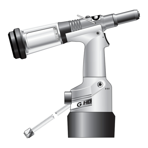
Avdel
Avdel Genesis G2HD User manual
Avdel
Avdel 74405 User manual
Avdel
Avdel 7536 User manual
Avdel
Avdel eRiv User manual

Avdel
Avdel TX2000 User manual
Avdel
Avdel TX2000 User manual

Avdel
Avdel 7385 User manual

Avdel
Avdel TX2000 User manual
Avdel
Avdel Genesis G1 User manual

Avdel
Avdel Genesis G4 HD Heavy Duty User manual
Avdel
Avdel 7271 User manual
Avdel
Avdel Avbolt 07220 User manual
Avdel
Avdel Genesis 4 User manual
Avdel
Avdel 7539-300X Series User manual
Avdel
Avdel T40 User manual
Avdel
Avdel Genesis G3 User manual
Avdel
Avdel 7551 User manual
Avdel
Avdel 71404 User manual
Avdel
Avdel Genesis G2LB User manual
Avdel
Avdel 74201 User manual


