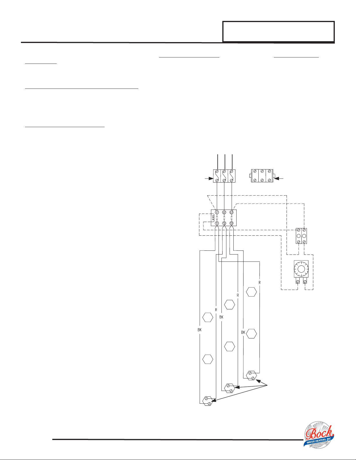
Bock Water heaters Energy Saver 50A SF Series User manual


This manual suits for next models
11
Other Bock Water heaters Water Heater manuals

Bock Water heaters
Bock Water heaters CE050 User manual

Bock Water heaters
Bock Water heaters SideKick 80SK User manual

Bock Water heaters
Bock Water heaters Energy Saver 66W-399 User manual

Bock Water heaters
Bock Water heaters Commercial/Industrial Water Heaters User manual

Bock Water heaters
Bock Water heaters Electric Water Heaters User manual

Bock Water heaters
Bock Water heaters Gas 120PG-BCS User manual

Bock Water heaters
Bock Water heaters OT300 Service manual

Bock Water heaters
Bock Water heaters EZ 75-76PDV-C Service manual

Bock Water heaters
Bock Water heaters CE050 Service manual

Bock Water heaters
Bock Water heaters 75-76SKG Service manual

Bock Water heaters
Bock Water heaters 80030 User manual

Bock Water heaters
Bock Water heaters Electric Water Heaters User manual

Bock Water heaters
Bock Water heaters 30ST User manual

Bock Water heaters
Bock Water heaters OT300-A Service manual

Bock Water heaters
Bock Water heaters LCE6-1 User manual

Bock Water heaters
Bock Water heaters 80STE User manual

Bock Water heaters
Bock Water heaters 32E Guide

Bock Water heaters
Bock Water heaters PowerGas 32PG User manual

Bock Water heaters
Bock Water heaters 100PDVI-250-XA 225 User manual

Bock Water heaters
Bock Water heaters EZFIT Service manual


Popular Water Heater manuals by other brands

clage
clage German pool CEX13 operating instructions

Noritz
Noritz proTough NR98SV installation manual

DeDietrich
DeDietrich KALIKO TWH 200 EV Installation and service manual

veito
veito FLOW Installation and operating instructions

ICI Caldaie
ICI Caldaie COSMOGAS AGUATANK 150 Instructions for installation, use and maintenance manual

Savio
Savio Laser 11 A Instruction manual for installation and use

Kenmore
Kenmore 153.582400 Use & care guide

STIEBEL ELTRON
STIEBEL ELTRON Eltronom SHU 5 S Operating and installation instructions

clage
clage E-Mini Series Operating and installation instructions

Solar
Solar SunX 317365-002 instruction manual

Bradford White
Bradford White EF Series Service manual

Dimplex
Dimplex ECSd125-580 Installation and user instructions

Dux
Dux 32FCR6N installation manual

Noritz
Noritz N-132M Owner's guide and installation manual

TESY
TESY GCV7/4S 10047 Instructions for use and maintenance

A.O. Smith
A.O. Smith Gphe 50 instruction manual

Rinnai
Rinnai REP199i Installation and operation manual
 Operation and maintenance instructions")
Toyotomi
Toyotomi Oil Miser OM-148 (Type D) Operation and maintenance instructions