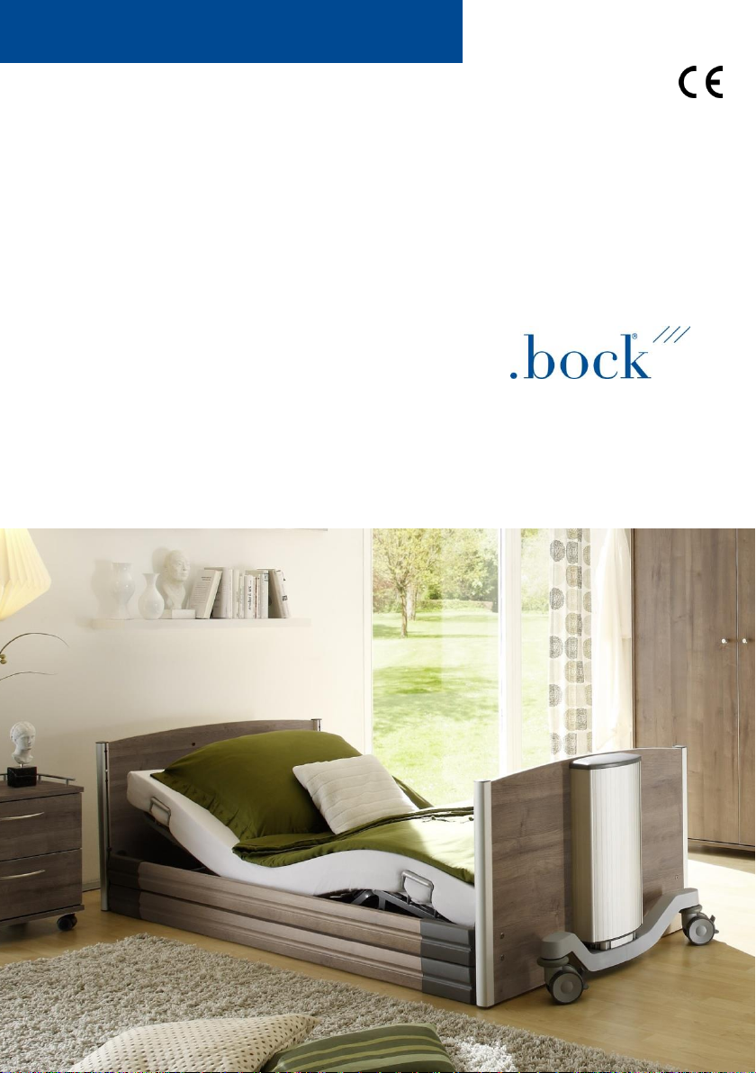
BOCK floorline 9.5 80 Installation and operating instructions
1
Assembly and operation manual
Nursing care bed
floorline 9.5|80

2
Dear valued customer,
with your decision to purchase a nursing care bed from Hermann Bock
GmbH, you are receiving a long-lasting care product with superior function-
ality at the highest safety level. Our electrically operated nursing care beds
guarantee optimal lying comfort and allow professional care at the same
time. This product was designed with a focus on the elderly, whose confi-
dence must be reinforced and whose life needs protection. With this health
care product, we meet these requirements.
We urge you to prevent potential malfunctions and the risk of accidents by
complying strictly with the safety and operating instructions and by carry-
ing out the necessary maintenance.
Klaus Bock

3
Table of contents
1Preface and general instructions ......................................................................... 4
1.1 Intended purpose.............................................................................................. 4
1.2 Definition of person groups .............................................................................. 5
1.3Safety instructions............................................................................................. 6
1.4 Service life / warranty ....................................................................................... 7
1.5 Requirements for the installation location ....................................................... 7
1.6 Type plate.......................................................................................................... 8
2General description of the functions.................................................................. 10
3Electric parts ..................................................................................................... 14
3.1 The drive unit .................................................................................................. 14
3.2 Caution: Electric drive ..................................................................................... 14
3.3 The drives / lifting columns ............................................................................. 15
3.4 The external switch mode power supply SMPS .............................................. 15
3.5 The controller.................................................................................................. 16
3.6 The hand control ............................................................................................. 18
3.7 Hand control - lock functions .......................................................................... 20
3.8 Second controller (optional as accessory)....................................................... 20
3.9 Rechargeable Battery (optional as accessory) ................................................ 21
4Assembly and operation .................................................................................... 23
4.1 Technical data ................................................................................................. 23
4.2 floorline 9.5|80 ............................................................................................... 24
4.3 Bed extension.................................................................................................. 30
4.4 Emergency lowering - back part...................................................................... 31
4.5 Change of location .......................................................................................... 32
4.6 Transport, storage and operating conditions.................................................. 32
4.7 Function notes................................................................................................. 32
4.8 Disposal ........................................................................................................... 32
4.9 Troubleshooting .............................................................................................. 33
5Accessories........................................................................................................ 34
5.1 Special dimensions .......................................................................................... 34
6Cleaning, maintenance and disinfection ............................................................ 35
6.1 Cleaning and care............................................................................................ 35
6.2 Disinfection ..................................................................................................... 36
6.3 Avoidance of hazards ...................................................................................... 36
7Guidance and manufacturer's declaration ......................................................... 37
8Regular inspections with service........................................................................ 38
4
1Preface and general instructions
The various bed systems from Hermann Bock meet special requirements for the use in
care and treatment facilities as well as for home care. Reliable functionality and a long
product life make each bed particularly valuable. Our beds need little maintenance with
proper operation and care. Each bed from Hermann Bock must pass quality testing in a
final inspection before it is shipped anywhere. The beds are manufactured according to
the current standards and compliant with the statutory requirements for medically used
beds, and tested accordingly.
The beds comply with the EN 60601-2-52 standard. The electrical building components
comply with safety standard EN 60601-1 for medical devices. Nursing care beds are med-
ical devices and are to be assigned to Class 1.
These standards divide the beds in five different areas of use:
1. Intensive care in a hospital; intensive care bed
2. Short-term care in a hospital or other medical facility; patient bed in the hospital
3. Long-term care in medical environment; stationary nursing care bed
4. Care at home, pure so-called “HomeCare bed”
5. Home-care nursing service
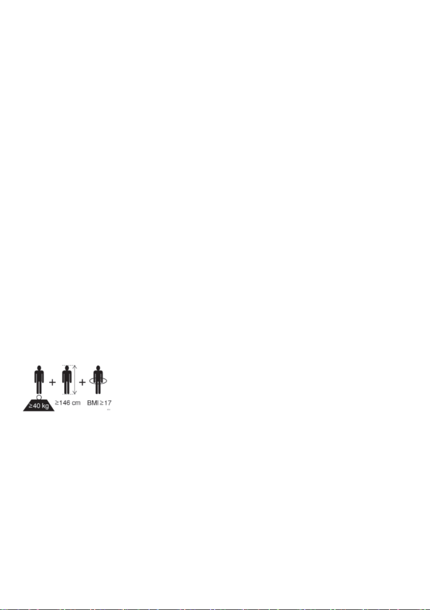
1.1 Intended purpose
The nursing care bed is suitable for persons (adults) in need of
care who are at least 146 cm tall. The person's weight must not
exceed 185 kg and must be over 40 kg. The body mass index
(BMI = weight of the person (kg) / body height of the person (m)2)
must be greater than or equal to 17.
The nursing care bed may be used in homes for the elderly or nursing homes and rehabil-
itation facilities. It is used to alleviate a disability and/or to facilitate the lives of people
who are in need of care or to make the work of their caregivers easier. Accordingly, the
health care beds are designed to be used for the application environments 3 to 5. Any
other use is considered improper and is excluded from a possible liability claim.
The Trendelenburg function may be used exclusively under supervision of medical profes-
sionals. The nursing care bed is not suitable for use in hospitals. It is also not designed to
transport patients. The beds can only be moved within the patient's room - even during
patient positioning - for cleaning or better access to the patient, for example. After a
movement, lock the rollers and turn them in the longitudinal direction of the bed (im-
portant for Trendelenburg, anti-Trendelenburg and comfort sitting position).

5
The bed is suitable for the re-use. Please observe the instructions for cleaning, care and
disinfection in these assembly and operation manual. Special attention must also be paid
to the information regarding the inspections.
Attention: The beds come with no special connection options for a potential equalisation.
Electrical medical devices connected to the patient intravascular or intracardiac may not
be used. The operator of the medical products has to ensure that the combination of the
equipment meets the requirements of EN 60601-1.
This user manual contains safety instructions. All persons working with the beds must
be acquainted with the contents of these instructions. Improper operation can result in
personal injuries.
1.2 Definition of person groups
Operator
Operators (e.g. medical supply stores, specialist dealers, facilities and cost units) include
all physical or juridical persons, who use the beds or have the beds used for medical pur-
poses. The briefing on the use of the product shall generally be conducted by the operator.
User
Users are persons whose training, experience or briefing on the product allows them to
operate the nursing care bed or carry out works on it. The user is able to recognize possible
hazards and/or to avoid them and to assess the health condition of the patient.
Patient/resident
Person with one or more disabilities, one or more activity restrictions, one or more par-
ticipation restrictions or a combination thereof.
Qualified personnel
Employees of the operator are referred to as qualified personnel. They are entitled to
deliver the nursing care bed, assemble, dismantle and transport it, on the basis of their
training or instructions. Besides knowing how to operate, mount and demount the nursing
care bed, these persons must be instructed according to the guidelines concerning the
cleaning and disinfection of the nursing care bed.

6
1.3 Safety instructions
The intended use/operation of all moving parts is as important for the safety of the person
in need of care as well as for the relatives and the caregivers/nursing staff to avoid poten-
tially dangerous situations. This requires the correct installation and operation of the bed.
The individual physique of the person in need of care as well as type and the extent of
their disability must be taken into account by all means when operating the bed.
Avoid dangers, accidental motor adjustments and incorrect operation by using the disa-
bling function. When the operator, e.g. the nursing staff/caregivers or the care providing
relative leaves the room, the entire operating functions of the bed should be disabled via
the hand control. This is achieved by operating the key of the hand control. First, lower
the lying surface to the safety position and activate the lock function with a twist of the
key (located in the keylock on the backside). Remove the key and check the function of
the hand control for safety reasons. Make sure that it is indeed locked.
These recommendations apply particularly:
-if the person in need of care cannot operate the hand control safely due to cer-
tain disabilities;
-if the person in need of care or the caregivers could be at risk due to those acci-
dental adjustments;
-if the side rails are in a raised position and there could be danger of trapping and
crushing,
-if children are unsupervised in the room with the bed.
Always make sure that the hand control (when not in use) is securely hooked in the sup-
port hook at the bed and cannot drop.
As a general rule, the bed should be operated by instructed nursing staff/caregivers, rela-
tives or in attendance of instructed persons.
When adjusting the lying surface, it is particularly important to ensure that no limbs are
placed within the adjustment range of the side rails. If the side rails are adjusted, pay
attention to the correct lying position of the person in need of care.
Prior to making any electrical adjustment, it should, as a general rule, be made sure that
no limbs are positioned in the adjustment range between the chassis and the head or foot
part, especially that there are no persons or animals in the area between the floor and the
raised lying surface. Danger of being crushed is particularly high in these areas. Always
beware of objects that are located close to or even below the nursing care bed. This can
lead to damages.

7
The permitted person’s weight depends on the total weight of the equipment that has
been mounted to the bed (mattresses and other electronic medical devices). For safe
working load, please refer to the type plate on the lying surface frame of the bed.
1.4 Service life / warranty
This nursing care bed was developed, designed and manufactured for safe operation over
a long period of time. With proper operation and maintenance, this nursing care bed has
an expected service life of 15 to 20 years. The service life depends on operating conditions
and frequency.
Attention: Unauthorised technical changes to the product voids all warranty claims.
This product is not approved for the North American market, particularly not for the
United States of America (USA). Distribution and use of the nursing care bed in these
markets, including through third parties, is prohibited by the manufacturer.
1.5 Requirements for the installation location
The company Hermann Bock GmbH is not liable for damages which might arise from the
daily usage on the floor.
To avoid floor indentations, floor should correspond to the recommendations of the FEB
- Fachverband der Hersteller elastischer Bodenbeläge e. V. (Association of Elastic Floor
Coverings Manufacturers). To do this, the technical information FEB No. 3 can be refer-
enced.
Hazard note from Bock
Simultaneous use of electrical appliances particularly in the vicinity of the operational bed may
result in small electromagnetic interactions of these electric devices, e.g. static noise in the ra-
dio. In such rare events, increase the distance of the devices. Do not use the same socket or
temporarily switch off the interference source and/or the disturbing or disturbed device.
If the bed should be operated with electrical medical equipment (contrary to its intended use),
the functions of the bed must first be disabled via the integrated locking function in the hand
control for the duration of the application.

8
1.6 Type plate
Each nursing care bed is marked with an individual and a general type plate.
Individual and general type plate
(1) Model designation
(2) Manufacture date: Day, month and year
(3) Serial number: Order number - running number
(4) Mains voltage, mains frequency and power input
(5) Duty cycle
(6) Drive protection class
(7) Maximum patient weight / safe working load
(8) Manufacturer
(9) Symbols (located on the right side)
9
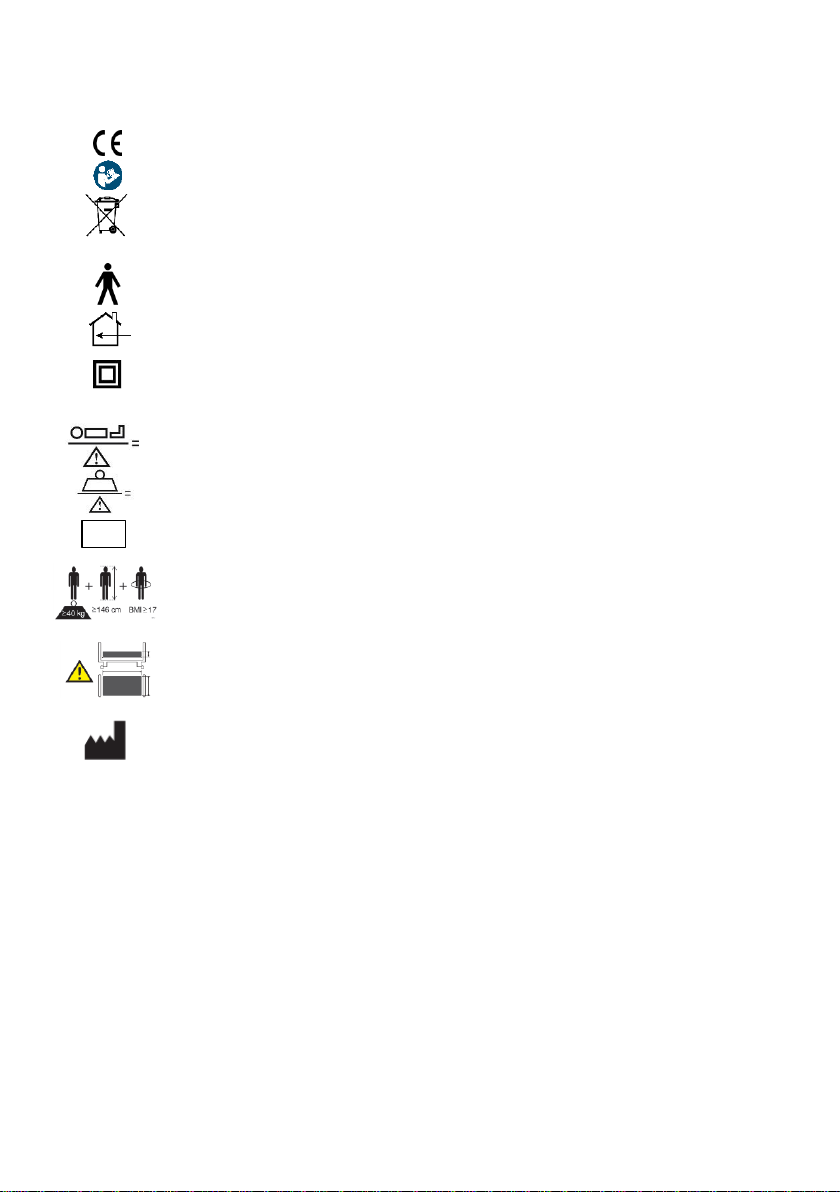
Explanation of the symbols:
Conformity mark according to the medical device regulation
Symbol for observance of the user manual
Within the European Union, this product must be disposed
via the separated municipal waste. Product may not be dispo-
sed of as household waste.
Medical application part type B
Use only in dry rooms
Protection class II (double insulation, insulated for protection)
IPX4
Protection of electrical equipment against splashing water
Symbol for maximum patient weight
Symbol for safe working load
Symbol for the identification of a medical device
Patient population
Follow the instructions appropriate for mattress size and
thickness
Address of the manufacturer
MD
10
2General description of the functions
Construction design and function
Corrosion protection
The Hermann Bock GmbH nursing care beds are developed and constructed in such a way
that they can function long and safely. For this reason, all materials that may corrode are
protected accordingly. All metal parts are equipped with a surface protection. The steel
parts are either galvanised or stove-enamelled with a PES powder coating and the alumin-
ium profiles are anodised.
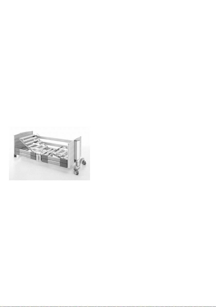
The lying surface with 4 function areas
The lying surface consists as standard of a slatted comfort frame (can alternatively be fit-
ted with aluminium slats or special suspension systems) and is divided into four functional
areas: Backrest, solid seat, upper and lower leg rest.
The circumferential lying surface frame is welded from a steel/aluminium tube. The steel
tubes are stove-enamelled with a PES-powder
coating. The electric variable height adjustment
of the lying surface is carried out with protective
low-voltage DC motors (29 to 35V), and con-
trolled with the smooth keys of the hand control-
ler. The backrest can be adjusted electrically. The
leg part consists of a foot support that is divided
into two parts. With a touch of a button on the
hand control, each individual position can be ad-
justed continuously. In case of a power failure the back part that can be lowered by loos-
ening the tube clip.
The height adjustment
The height adjustment of the beds is carried out through two telescopic aluminium lifting
columns. These are each mounted on a foot tube with two castors. The surface of the
tubular steel structure is stove-enamelled with a PES-powder coating. This is covered with
an appealingly designed plastic cladding.
The side rail
Each nursing care bed can be equipped on both sides with two side rails at a special safety
height. The side rails can be lifted and lowered through a rail. The sliding pieces run par-
ticularly smoothly and quietly with an impact damper, and each end is fitted with a func-
tional cap. The side rail can be easily operated through an ergonomically designed release
button. Depending on the model, shorter or longer divided side rail variations are availa-
ble.

11
Operating the telescopic divided side rails
Each side rail element can be adjusted independently from the rest
of the side rail parts. The release buttons for adjustment are on the
bottom of the telescopic post and on the top of the appropriate end
panel of the nursing care beds, right next to the metal guides for the
side guard rail bars.
To lower the side rail element, hold the upper knob (1) of the middle
post with one hand, lift it up slightly, and with the other hand press
the release button (2) on the middle post in the inner direction.
The side rail opens at the corresponding place and can be easily low-
ered downwards as far as it will go (3). The side rail is now diagonal.
To also lower the other side, please hold the side rail on the side of
the end panel at the gripping groove (4), and slowly raise the side
rail somewhat. Now, you can fully press the release button (5) and
slowly lower the side rail.
Please observe:
Be sure to raise the side rail slightly, and only then press
the release button! Failure to do so will result in dam-
age to the release.
The side rail is now in the lowered position.
If the side rail element should be placed in the top position to aid in
fall prevention, reach with both hands in the centre of the gripping
groove (6) in the upper side guard rail, and pull it upwards until you
hear it click into place at both ends. The side rail is now in a pulled-
up position.
Hazard note from Bock
When using the telescopic (split) side rail on this nursing care beds, four adjustable feet must be
screwed under the lying surface to prevent the telescopic posts of the side rail from touching
the floor. The screwed-on adjustable feet allow lowing of the bed only to a minimum lower
height of 15.5 cm.
12
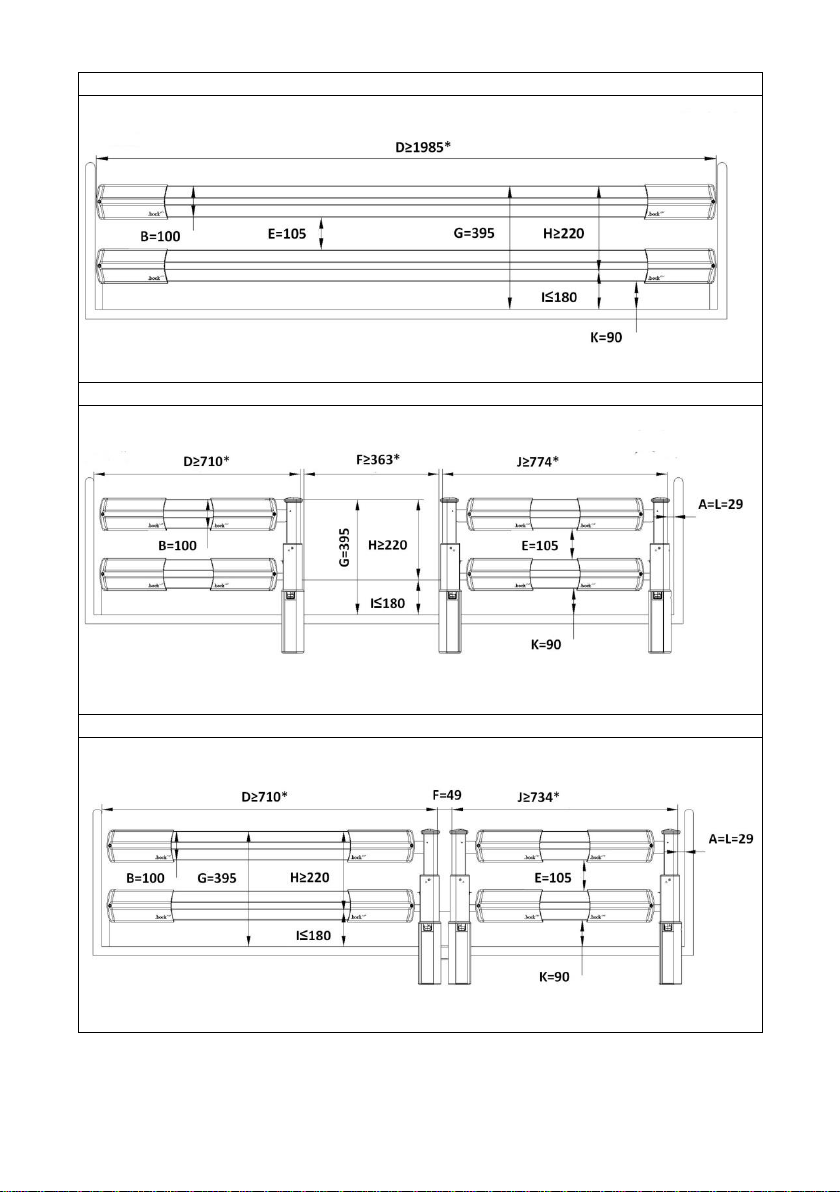
Fig. 1: Continuous wood side rail
Fig. 2: Telescopic wooden side rail, solo post in the middle
Fig. 3: Telescopic wooden side rail, double post in the middle
All dimensions in mm.
(*) Depending on the length of the lying surface. The single post at the head and leg end is optional. The
dimension in brackets is optional.

13
Legend
A: Distance between the head part and the side rail
B: Height 1 of side rail
C: Height 2 of side rail
D: Width 1 of the side rail
E: Distance between the elements within the side rails
F: Distance between the divided side rails
G: Distance between the lying surface and the upper edge of the side rail
H: Height of the top edge of the side rail above the mattress without compression
I: Thickness of the mattress for the intended use
J: Width 2 of the side rail
K: Smallest dimension between side rail and lying surface (or the panel, if any)
L: Distance between the foot part and the side rail
Item numbers
Designation item no.
Fig. 1: Continuous wood side rail
Wooden side rail (two bars) 91703
Fig. 2: Telescopic wooden side rail, solo post in the middle
Wooden side rail (two bars) 91868
Fig. 3: Telescopic wooden side rail, double post in the middle
Wooden side rail long head part (two bars) 91704
Wooden side rail short foot end (two bars) 91705
Hazard note from Bock
Use only original Bock side rails, which are available as accessories for every nursing care beds.
Use only technically flawless and non-damaged side rails with the permissible gap dimensions.
Make sure that the side rails are engaged securely.
Before installation of the side rail and each new use, inspect all mechanical parts on the bed
frame, and all parts of the side rails, and all parts which secure the side rails, for any possible
damages.
The operation of the side rail should be done with great care. Fingers can be quickly pinched
between the longitudinal pieces.

14
3Electric parts
3.1 The drive unit
The drive unit consists of individual drives for the electrical adjustment of the back and
leg rest part. The level adjustment takes place via two lifting columns that are attached to
the head or foot end. The internal control box includes a switch box with a rectifier in
which the input voltage is converted into a protective low voltage of max. 29 VDC direct
current. The motors, lifting columns and the hand control function with this non-hazard-
ous low voltage.
A power adjustment provides constant speed. Therefore, the safety functions comply with
protection class II and the moisture barrier protection type IPX4.
The maximum duty cycle is specified on the (type plate) of the bed. For example, 10% duty
cycle (2 min. ON / 18 min. OFF) means that any electronic adjustment can be performed
for a max. of 2 minutes within a timeframe of 20 minutes (protection against overheating).
If the maximum setting time of two minutes is exceeded by two minutes (e.g. someone
plays continuously with the hand control), which could lead to overheating of the control-
ler or drives, the thermal fuse immediately shuts off the power supply to the bed. After a
cooling time of approx. one hour, the power supply in the controller is automatically re-
stored.
3.2 Caution: Electric drive
The electrically operated nursing care bed enables the person in need of care to support
the recovery process psychologically and physically and at the same time relieve pain
through its various functions. Electrically operated beds that are medical products need
special care in regards to constant safety checks. This includes safety-conscious handling
of the bed, daily inspection of electrical equipment and proper maintenance and cleaning.
To prevent damages to the cables, wiring should be conducted outside of the area in
which damages could be caused. Furthermore, avoid touching the sharp parts. To prevent
injury through an electric shock, avoid the possibilities of too high contact voltages. These
circumstances may especially be the case if the power cable is damaged, if inadmissible
and excessive leakage currents exist, or if liquid was spilled into the motor housing, e.g.
during improper cleaning. This damage can cause malfunction of the controller, which
could result in unwanted movements of single bed elements, posing a risk of injury for the
operator and the person in need of care.

15
3.3 The drives / lifting columns
Hermann Bock GmbH equips nursing care beds with various drive systems from the com-
pany's DewertOkin and Baumeister.
Each drive consists always of four main components.
–Housing
–Motor
–Gear
- Spindle with nut
The housing principle of the individual drive guarantees the permanent function of all
drive components. The design of the interior of the housing creates an essential prereq-
uisite for the precise mounting of the drive technology and particularly simple assem-
bly/disassembly due to its detailed internal design.
3.4 The external switch mode power supply SMPS
The plug-in part of the external switch mode power supply (SMPS) is an electronic trans-
former, which warms up only to a minimum degree under load and it is equipped with
electronic performance monitoring. The result is a constant voltage up to the maximum
load (no loss of speed) and a high level of protection against overloading. The external
transformer ensures safety right from the socket because it converts the voltage directly
into the 29V safety low-voltage which is used to actuate the bed. It is connected via plug
coupling to the mains supply line feeder cable and can be replaced separately if defective.
The plug-in part of the external switch mode power supply complies with the European
directives for electrical household appliances. In standby mode, it also has a low energy
consumption of maximum 0.5 Watt and can be used internationally with variable input
voltages from 100 V to 240 V. Electromagnetic alternating fields are not measurable on
the SMPS adapter.
The external switch mode power supply
16
3.5 The controller
The floorline 9.5|80 is equipped with a DewertOkin GmbH controller (Generation 1 / MCL
2 or Generation 2 / MCL 3). Alternatively, the floorline 9.5|80 can be equipped with a
Smart-Care-Control (SCC) from Hermann Bock GmbH.
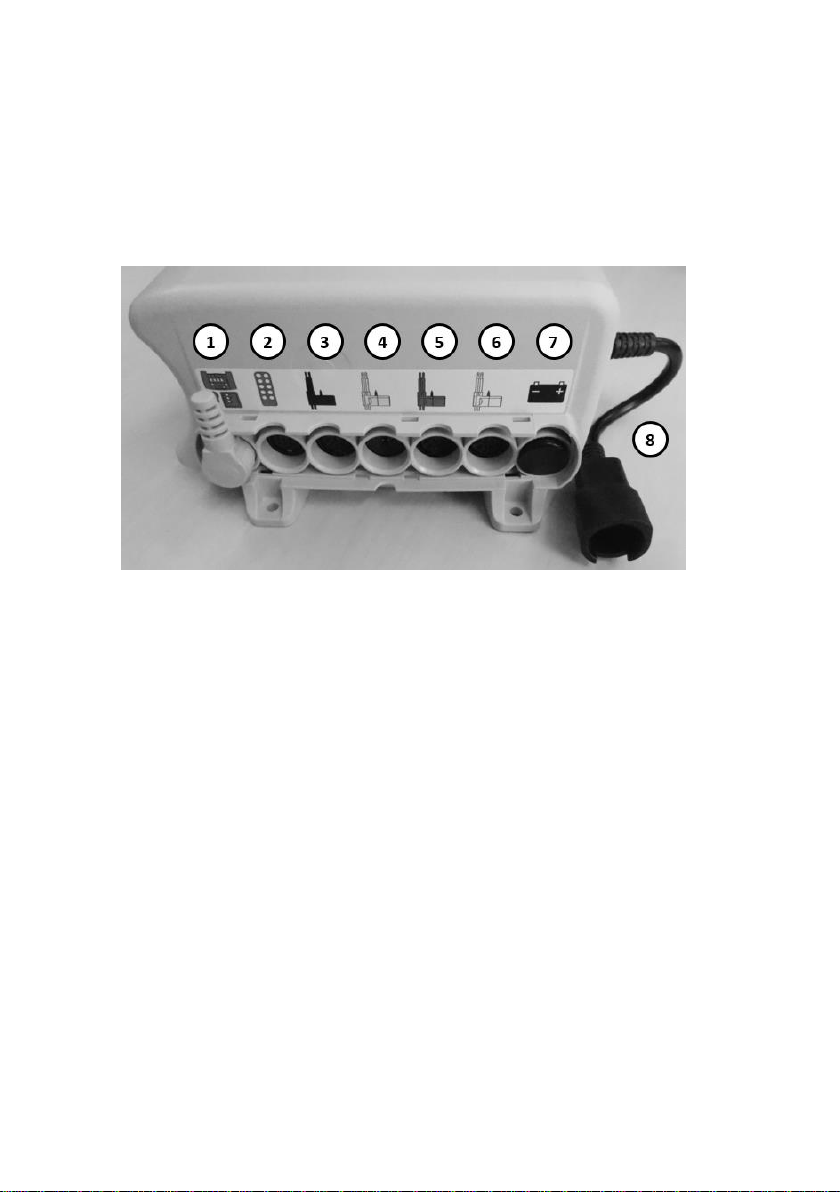
Controller Generation 1 / MCL 2
Controller Generation 1 / MCL 2
Four drives can be connected to the controller (sockets 3,4,5 and 6). The colour coding
can be found in chapter 4 "Assembly and operation". A floor lighting can be connected to
the connection socket for the hand control (socket 2), which in turn has a socket for the
hand control. Please make sure that a dummy plug is attached to the connector for a bat-
tery (socket 7) if no battery is connected. The socket for the additional control element
(socket 1) must be fitted with a so-called jumper plug. A reading lamp can be connected
to the side pigtail connection (socket 8).

17
Controller Generation 2 / MCL 3
Controller Generation 2 / MCL 3
The connection sockets are identical to the Generation 1 controller (MCL 2) described
above. The pigtail connector is located on the top of the controller.
SCC Controller
SCC Controller
The socket 1 is a CAN-BUS connection which can also be used to connect a sensor pad for
a bed-off detection. Further details can be found in the separately supplied assembly and
operation manual of the Smart-Care-Control unit. A Y-cable is plugged into socket 2 to
which the floor lighting and the reading lamp are connected. The supplied hand control
must be connected to socket 3. The connector sockets 4, 5, 6 and 7 are intended for the
individual drives in the scissor and lying surface.

18
3.6 The hand control
The series hand control is equipped with a built-in locking device, which allows the care-
givers to lock the hand switch via a key completely or partially for its operation.
The lockable hand control, first-fault protected
The base functions can be controlled through the ten operation keys on the hand control.
The four symbols in the middle indicate a special function that can be performed by sim-
ultaneously pressing the adjacent keys. The individual keys are marked with correspond-
ing symbols. The servomotors run until as long as a corresponding key is pressed and held.
A coiled cable allows the necessary freedom of movement while operating.
With the rear-mounted suspension unit, the hand control can be attached to the side rail
- particularly when cleaning and during the maintenance of the bed. Thus, a possible dis-
ruptive position of the hand control can be avoided by simply attaching it to any preferred
spot on the bed.
Hazard note from Bock
All drive components must not be opened!
Troubleshooting or exchanging single electrical components may only be performed only by
special qualified personnel.
Hazard note from Bock
The motors meet the water protection standard IPX4. Do not squeeze/crush the cables. Adjust-
ment of moving parts may only be used for the intended use. Hermann Bock GmbH assumes no
liability for unauthorized technical changes.
.
Hazard note from Bock
Do not try to fix failures on the electrical equipment itself. It could be fatal! Either call the cus-
tomer service of Hermann Bock GmbH or an authorised/licensed electrician who conducts the
troubleshooting in compliance with all relevant VDE regulations and safety regulations.
Hazard note from Bock
Do not exceed the maximum duty cycle of 2 minutes. Observe a subsequent break of at least
18 minutes by all means.

19
Function keys:
(*) The comfort sitting position just moves upwards. All adjusted positions can be lowered
by pressing key 13.
(**) When using the Trendelenburg function, unlock the brakes on one end piece. All cas-
tors must be parallel to the longitudinal axis of the bed.
(***) Not possible when using the (divided) telescopic side rails.
(1)
Back part upwards
(2)
Back part downwards
(3)
Floor lighting:
Push keys (1) and (2) simultaneously
(4)
Lower leg part upwards
(5)
Lower leg part downwards
(6)
Lightening / reading lamp:
Push keys (4) and (5) simultaneously
(7)
Lying surface upwards
(8)
Lying surface downwards
(Interim stop at the 37.5 cm exit position,
safety stop at 27.5 cm safety position)
(9)
Reset:
It is absolutely necessary to carry out this work during
initial commissioning and after disconnection from
the power supply!
(The reset motion is carried out by pushing keys (7)
and (8) simultaneously. In doing so, after approx. 8
seconds, the bed moves slowly in the lowest position.
After a signal beep from the controller, reset is carried
out completely.)
(10)
Comfort sitting position upwards (*)
(11)
Foot-lowering position (anti-Trendelenburg)
(12)
Head-lowering position (Trendelenburg) (**)
(13)
Lying surface, back and lower leg part downwards
(moves to safety spot at 27.5 cm)
(14)
Low function:
Push keys (11) and (12) simultaneously
Caution: foot crushing risk
(Second interim stop at 15.5 cm for accessories and
telescope posts at 9.5 cm in lower position (***))
20
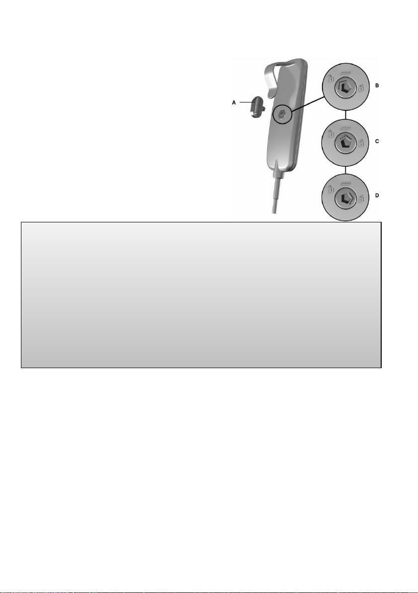
3.7 Hand control - lock functions
The hand control comes with an integrated disa-
bling function that can be activated and deac-
tivated with the corresponding key. To disable the
entire electrical function, insert the key in the key-
lock on the backside and turn the lock function on
or off with a corresponding twist of the key.
A: Socket key
B: Release hand control keys
C: Head-lowering position (Trendelenburg - key
11) and low function (keys 12 and 13)
closed
D: Release hand control keys
3.8 Second controller (optional as accessory)
The nursing care bed can optionally be equipped with an additional controller.
For this purpose a second control box is mounted in the bed, which is connected to socket
2 of the controller. The hand control in socket 1 and the second controller in socket 2 are
plugged into this second control box. Sockets 3, 4 and 5 remain unassigned and are
equipped with a blind plug.
Hazard note from Bock
Make sure that the cable routing of the hand control is not routed under of one of the alumin-
ium longitudinal frames. When the bed is completely lowered (low floor position), the cable
could be damaged if routed underneath.
Perform a reset before use and after any separation from the mains.
Pay attention to the position of the castors, particularly at comfort sitting position, Trendelen-
burg and anti-Trendelenburg.
Keep in mind that when using accessories and (divided) telescopic side rails, the bed can only
be moved to the second safety stop (15,5 cm).
When lowering the nursing care bed in the lowest position (low floor position), there is a high
risk of crushing (feet, toes, and objects, e.g. cables) underneath the aluminium longitudinal
frames and/or the bed end pieces.
This manual suits for next models
6
Table of contents
Other BOCK Indoor Furnishing manuals


Popular Indoor Furnishing manuals by other brands

Argos Home
Argos Home Chile 501/7531 Assembly instructions

Forma Ideale
Forma Ideale ELEGANT KL 3K H225 Assembling Instruction

Philips
Philips Ledino 66701/87/16 Specifications

snug
snug The Cloud Sundae Assembly instructions

kingparrot
kingparrot b2t Assembly instruction

SixBros
SixBros CT-3802N Assembly instruction


Xxxlutz
Xxxlutz 22-365 Series Assembly instructions

Touchstone
Touchstone Whisper Lift II PRO owner's manual

WIEMANN
WIEMANN WIEMANN 991404 manual

Furinno
Furinno FNCL-33002 Assembly instruction

Monarch Specialties
Monarch Specialties I 2396 Assembly instructions

Furniture of America
Furniture of America FOA-DK915 Assembly instructions