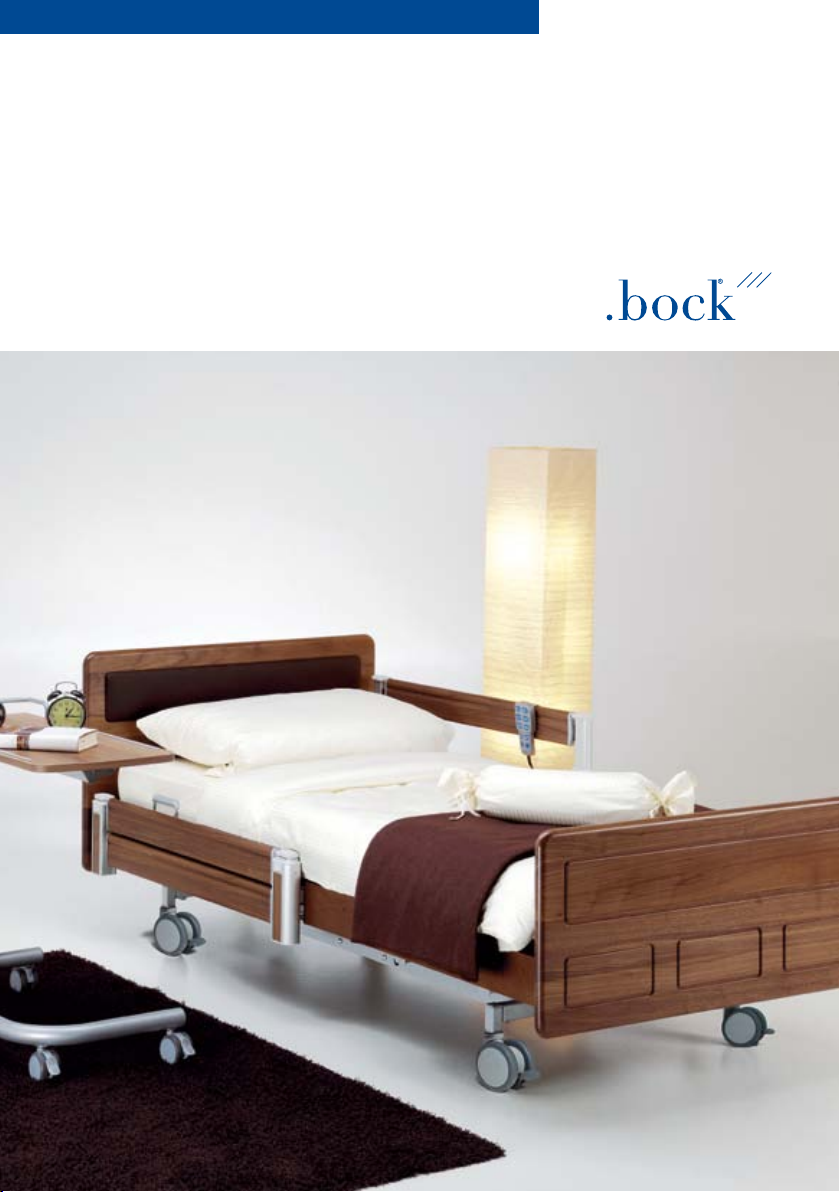
BOCK combiflex.fc Installation and operating instructions
Modell fc 200, Buche massiv, Walnuss gebeizt, Kopfteil mit
Lederbesatz dunkel
Assembly and operation manual
combiflex fc

Dear Customer,
In deciding to buy our comfort sleep system combiflex fc you
have opted for a first class product in functionality and reliability.
This product has been manufactured and tested in accordance
with the current valid standards for medical used beds.
Sleep is individual- and so is combiflex fc. The combiflex fc
grows with your requirements; even later adjustments are pos-
sible without a problem. Equip the comfort system individually
with the combiflex fc wooden frame, optionally with the prac-
tical, telescopic side rails. Decide on the ripolux® lying surface
system. What counts with this system are your needs and an
absolutely convincing comfort.
Yours faithfully,
Klaus Bock

3
Content
1. General notes
1.1 The first impression – Visual inspection
1.2 Security advice
2. Cleaning, care and disinfection
2.1 Cleaning and care
2.2 Disinfection
2.3 Avoid hazards
3. General description of function
3.1. Constructive design and function
3.2 How to carry out the quick and easy assembly:
3.3 Caution: Personal injuries
4. The ICS Sytem
4.1 What is ICS?
4.2 The drive and the handset
4.3. Analysis function of the handset
4.4 Caution: Electrical operation
4.5. The mains isolation
5. Accessories
5.1 Acessories
5.2 Mattresses
5.3 Special mattress ripocare
6. Setting up and operating
6.1 General notes
6.2 Special features
6.3 Scope of delivery
6.4 Technical Data
6.5 Assembly of the combiflex fc bed-in-bed system
6.6 Changing of the bed-in-bed system to a comfort bed
6.7. The assembly of the telescopic splitted side rails and side
paneling of the frame
6.8 Disposal
6.9 Troubleshooting
4
6
9
16
21
23

4
1. General notes
The various bed systems that are made by Hermann Bock GmbH
meet the special requirements for use in rehabilitation and the-
rapy establishments as well as for care at home. Their reliable
functioning and long service life mean that all our beds are of a
particularly high quality. Our beds need little maintenance when
used and inspected properly. No bed leaves the Hermann Bock
production plant until it has passed final quality inspections and
has been tested by a technical inspectorate in Germany named
TÜV. Every health bed thus meets the requirements of directive
93/42/EEC for medical products.
The beds are tested and manufactured on the basis of the cur-
rently applicable European standards for electrically operated
hospital beds. The electric components of our beds conform
with safety standard EN 60601-1 for medical devices.
All nursing beds are subjected to a thorough functionality test
carried out on site by our qualified delivery staff. This is accom-
panied by an extensive instruction of the person being autho-
rized to operate the bed in order to familiarize the operating
person with the bed‘s functionality and its safe handling.
For further information and support, please read this manual for
assembly and use and the contained safety Guidelines.
1.1 The first impression – Visual inspection
Please conduct a thorough visual inspection of the bed to check
for external damages and completeness prior to the assembly
and initial operation. Please note that the bed has to be consi-
dered by you to be in a sound and faultless state before continu-
ing with the next step that informs you about the intended use
of the individual bed elements set out in the following functio-
nal description.
1.2 Security advice
Please consider the following:
– Because of careless grapping into the adaptation mecha-
nism underneath the lying surface, or between the lying
surface and the electrical adjustable components, while
adjusting the bed can lead to bruises on the extremity.
– Do not leave your children play unattended with the bed
or accessories of the bed!
– When leaving the bed, the head and foot part of the
lying surface should be lowered in its lowest position.
– All adaptation mechanisms and motors have to have the
space to work without restrictions.
* Warning note from Bock
The user of this product is
highly recommended to
thoroughly read this assem-
bly- and operation manual
in order to prevent poten-
tial damages and malfunc-
tions from occurring at the
assembly and initial ope-
ration
5
– Do never open the box or the plug of the motor! Due
to unauthorised opening and inappropriate repairs the
warranty claim expires. Furthermore, risks for the user
might occur.
– Repairs can only be carried out by specialized person-
nel!
– Handset, plug and motors are only supposed to be used
as in the manual specified purpose!
– Please check regularly if the cable or box is damaged. If
this should be the case do not use the bed. Exchange
the parts after consulting your dealer.
– Never let liquids infiltrate inside the motors or plug; it
might lead to electrical blows or short circuits.
– When you install the electrical cables please mind that
no sharp edges or kinks occur. The cables are not allo-
wed to go through the adaptation mechanism
Explanation of symbols used on name plate:
Mark of conformity according to guidelines for medical
products
The first digit indicates the protection class for shock-hazards
and penetration by solid objects
The second digit indicates the protection class for
penetration by water
„Medical equipment part, type B“
„Only to be used in dry environment“
Protection class II (duoble Iinsulation, protective insulation)
This product must be disposed to a selected waste disposal
within the european union. This product may not be disposed
together with unsorted domestic waste.
Take note of the accompanying documents
Thermal cut-out in the transformer
Doubly insulated transformer

6
2. Cleaning, care and disinfection
The individual bed elements are made up of high-quality mate-
rials. The surfaces are covered with a permanent polyester-coa-
ting.
All wooden components have an environmentally-compatible
surface-seal. The patented support-system ripolux consists of
high-quality synthetics. All bed elements are easy to clean and
cared for using wipe- and spray disinfection means according to
the applicable sanitary requirements with respect to the various
fields of application. Observing the following care instructions
will retain the usability and visual appearance of your nursing
bed for a long time.
2.1 Cleaning and care
Steel pipes and varnished metal components:
Please use a wet wiper and a customary, mild household deter-
gent for the cleaning and care of these surfaces.
Wooden-, decorative- and plastic elements:
All customary furniture cleaners and cleaning detergents can be
used. The cleaning of the plastic elements using a wet wiper
without detergent additives should generally be sufficient. For
the care of the plastic surfaces, you should use a product, which
is specifically suitable for plastics.
Drive:
In order to prevent the intrusion of moisture, the drive housing
should only be wiped with a slightly moist cloth.
> Bock top advice
Scrapes and varnish chip-
pings that go through
the entire varnish coating
should be preventively
sealed with appropriate
repair means against the
infiltration of moisture.

7
The ripolux support system:
To clean the plastic carrier and spring elements as well as the
base use a slightly moistened cloth without adding any cleaner,
or add a product that has been designed specifically for plastics.
If the support system needs particularly intensive cleaning, pull
off the spring elements and the carrier elements off the lying
surface frame. The plastic elements that you have removed in
this way can be cleaned or sprayed with hot flowing water. The
plastic elements can be sprayed with a suitable plastic cleaning
agent for disinfection. Most of the moisture can be removed
from the surface of the plastic by a gentle shaking, the remain-
der will dry within a short time. After drying thoroughly with no
residue, re-assemble the parts.
Alternatively the individual lying surface elements can be com-
pletely removed from the frame and cleaned.
2.2 Disinfection
All means in accordance to the standard EN 12720 can be used
for the wipe disinfection. However, you should apply only mild
and gentle means so as to retain the material resistance of the
plastic elements such as the drive housing, decorative elements,
ripolux and ripolan. Concentrated acids, aromatic and chlorinated
hydrocarbons, as well as detergents containing highly concen-
trated alcohol, ether, ester and ketone may damage the material
and should therefore be avoided.

8
2.3 Avoid hazards
Please make sure to consider the following guidelines with
respect to the electrical component parts of your nursing beds
as this crucial to avoiding hazards related to the cleaning and dis-
infection. The non-observance of these guidelines may result in
considerable damages of the electrical lines and the drive.
1. Disconnect the mains supply and position it in such a
way that contact with excessive amounts of water or
detergents can be excluded.
2. Check of all plug-connections for correct position accor-
ding to the instructions.
3. Check of the wires and electrical component parts for
damages. Should you detect any damages, do not per-
form any cleaning operations, but first have the defects
repaired by the manufacturer or authorized personnel.
4. Check the mains supply for residual moisture before
starting the operation and dry or blow out the device, as
the case may be.
5. On suspicion of the intrusion of moisture into the elec-
trical components, disconnect the mains supply imme-
diately resp. do not reestablish the connection. Put the
bed out of operation immediately, attach an appropriate
visible labeling and get in contact with the manufacturer.
* Warning note from Bock
It is absolutely not recom-
mended to use abrasive
cleansers resp. detergents
containing grinding parti-
cles, cleaning pads or stain-
less steel cleaners for the
cleaning. Do neither use
organic solvents such as
alkyl/aromatic halids and
ketones nor detergents con-
taining acid or alkaline.
Never clean the bed using a
water hose or high-pressure
cleaner, as this might lead
to the intrusion of fluid into
the electrical components
which causes malfunctions
and hazards.

9
3. General description of function
3.1. Constructive design and function
The lying surface
Besides a robust slatted frame, the lying surface of the Bock
health bed can be optionally equipped with two further lying
surface variants.
The combi-lying surface
The combi-lying surface is a steel lying surface with removable
ripolux® springs.
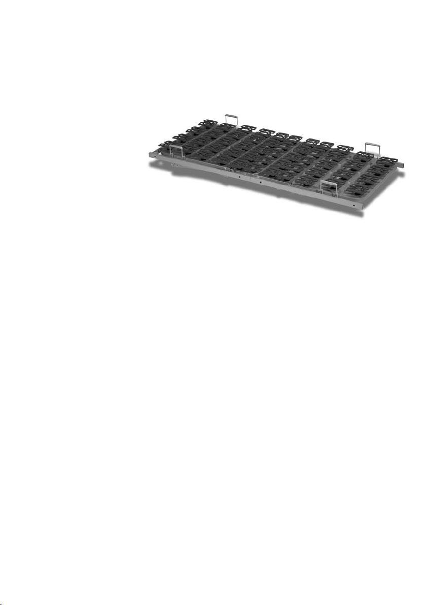
The patented anti-decubitus-system ripolux
The patented supporting-system ripolux is available for eve-
ry lying surface. ripolux consists of a wide lying surface frame
made of steel pipe and featuring four functional fields: back rest,
stationary seat part, upper and lower thigh rest. The four ripolux-
supporting elements made of high-quality plastic with all in all
51 individual spiroplex®-spring elements are fitted on the lying
surface frame. The electronic adjustment of ripolux takes place
without any restrictions and the same function as described
dependent on the bed model.
Back support Upper leg support
fixed seat section Lower leg support
Combi-lying surface
10
The scope of delivery for the ripolux includes:
4 Supporting elements made of plastic
51 Spiral springs
51 Rubber plugs
3.2 How to carry out the quick and easy assembly
The functional areas of all three versions are identical and are
spread over four areas: Back support, fixed seat section, upper leg
support and lower leg support.The frame for the lying surface is
made of welded steel tubing that has been covered with a PE powder
coating. The height of the lying surface is continuously adjustable
by means of 24 V direct current motors that are operated via the
easy-to-use hand control. The back support is electrically ad-
justable from 0 to 70 degrees.
The leg section consists of a two-part foot unit. Each individual
position can be continuously adjusted by pressing a button on
the hand control. The electronic hand control can also be used
for an automatic tri-function to raise the occupant‘s legs to a
stretched position and to make a bend in the area between the
heart and knees. The lower leg support automatically moves par-
allel to the lying surface in proportion to the upper leg support.
The leg section can be lowered with the aid of a 9-volt battery in
the event of a power failure.
The lifter
The height adjustment of the comfort bed combiflex fc is
carried out by a double lifter technique. The double lifter can be
height adjusted by two integrated single motors. The surface of
the steel tube construction has a PE powder coating.

11
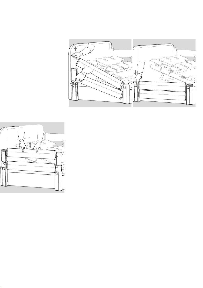
The splitted telescopic side rails
As an option the comfort bed combiflex fc can be equipped with
splitted side rails. The side rails serve as a protection against fal-
ling out and makes the getting in and out of the bed easy.
Usage of the splitted telescopic side rails
Each side rail can be adjusted individually. The trip lever for the
adjustment can be found on the telescopic bar.
In order to lower the side rail please grab with one hand the
upper knop on the telescopic bar, lift it a little bit and with the
other hand please push the button of the trip lever on the tele-
scopic bar (Fig. 2). The side rail can now be lowered easily. Now
the stands in the diagonal position (fig. 3).
Left: Fig. 2, right Fig.3
> Bock top advice
Should the side rail form
the diagonal position
(Fig.3) not be lowered but
raised, please grab the
knop of the telescopic bar
and raise it until the side
rail locks in.
12
In order to lower the other part of the side rail, please grab the
side rail on the part of the end panel. Push the locking device on
the end panel (Fig.4) and lower it slowly. Now the side rail is in
the lowered position (Fig. 5).
Left: Fig. 4, Fig.5
If one side rail element should be raised for the usage as a pro-
tection against falling out, please grab the upper side rail with
both hands and pull it to the top until you hear that it has locked
in. The side rail is now in the upper position (Fig.6).
Fig. 6

13
3.3 Caution: Personal injuries
The intended use of all moveable component parts is likewise
crucial for the prevention of hazards to the person in need of
care as for the safety of the relatives and/or nursing staff. This
requires of course the correct assembly and operation of the
bed. Avoid hazards due to unintentional adjustments related to
the drive and wrong operations occurring by using the locking
device.
These recommendations apply in particular,
> when, due to certain disabilities, the care recipient is
unable to operate the hand switch on its own.
> when the care recipient may be endangered due to
unwanted adjustments.
> when the side railings are in pulled up position and
there is a danger of bruises and contusions,
> when children are being left unattended in the room
with the bed.
Always make sure that the hand switch is, when not in use, put
into the suspension hook at the bed and cannot drop down.
The operation of the bed should generally only be performed
by instructed nursing staff resp. relatives or in the presence of
instructed persons. When adjusting the lying surface, it has to
be checked that the care recipient‘s extremities are not resting
between the side railings of the adjustment area.
Before making any electronic adjustments, it‘s of utmost im-
portance to check whether any part of the care recipient‘s ex-
tremities are resting in the adjustment area between the base
frame and head or foot rest, or if they are persons in the area
between the floor and the lifted lying surface. These are the
areas bearing a particularly high risk for bruises.
* Bock-Gefahren-Hinweis
During the electrical
adjustment of the lying
surface you have to take
care that the person does
not have a contact to the
side rails or that no extre-
mities are between the
side rails. This has also to
be considered when you
move the side rails, fur-
thermore the person has
to lay in the correct posi-
tion.

14
The distances between the side railings have to be less or equal
12 cm. Note that the side railings must not remain in diagonal
position, when these are being used.
Dimensions of a side railing in one piece
Dimensions of a partitioned side railing
> Bock top advice
When using different mat-
tress thicknesses, the mini-
mal height of 22 cm minus
the compression, mea-
sured from the upper edge
of the side railing above
the mattress, must not be
undershot. The use of hig-
her mattresses requires an
additional plug-in railing
which is available as equip-
ment.

15
Extract of the TÜV PS 51036 Inspection program, dimensions of
the side railings according to EN 60601-2-38
* Warning note from
Bock
– Do only use original side
railings from Bock which
are available as equip-
ment for every nursing
bed.
– Do only use technically
sound and undamaged
side railings that have
the permissible clea-
rances.
– Make sure that the side
railings click into place
– Check all mechanical
parts on the bed fra-
me and side railings
required for the fixing
of the latter for possible
damages before moun-
ting and every new
application.
– The control of the side
railings should always
take place with high dili-
gence, as it may easily
come to bruises of the
fingers due to the longi-
tudinal spars.

16
4. The ICS System
4.1 What is ICS?
The ICS is an entirely new solution for manufacturers of medi-
cal, healthcare, and wellness/ therapy beds. Intelligent control
systems (ICS) are able to control and monitor components and
parameters of a medical product in the most dependable man-
ner. Through an individual adaptation of more than 100 parame-
ters this micro-processor control system can be perfectly adju-
sted to medical applications.
Product Details:
− Micro-processor controls
− Soft Control
− Synchronization
− Memory function
− Special functions and processes, for example the main-
tenance position or parallel adjustment of all 4 motors,
for example comfort sitting position
− Easily programmable, approx. 100 parameters (pre-)
adjustable
− Safe disconnecting and end position, for example
collision protection
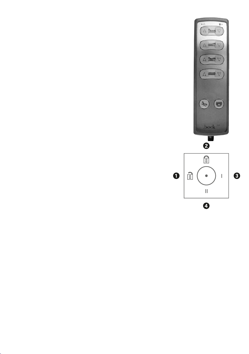
4.2 The drive with the hand set
By an ergonomic designed hand set the base functions are
assessable. The large buttons ensure a safe use.
The single buttons are labeled with the corresponding symbols.
The motors do work as longs as the button is pushed. A spiraled
cable offers the needed free space.
17
The hand set of the combiflex fc
The following function can be controlled by pushing the buttons:
Function button 1 Back rest up
Function button 2 Back rest down
Function button 3 Lower leg part up
Function button 4 Lower leg part down
Function button 5 Auto shape up
Function button 6 Auto shape down
Function button 7 Lying surface up
Function button 8 Lying surface down
Function button 9 Comfort sitting position
Function button 10 Light underneath the lying surface
5 and 6 Buttons pressed simultaneously :Reset function
By pressing the button no. 9 the comfort sitting position goes
only up. All positions have to be lowered individually.
The hand control also has an integrated disabling function that
can be activated or deactivated by the key (Fig 1). To disable the
entire electrical function, insert the key into the lock located on
the backside and activate or deactivate the disabling function
with a corresponding twist of the key.
Deactivation position of the handset 1:
Comfort-sitting position (button 9) is locked,
all other functions are enabled.
Deactivation position of the handset 2:
All functions of the handsets are locked.
Deactivation position of the handset 3:
All functions of the handset are enabled.
Deactivation position of the handset 4:
Without function.
1
3
5
7
9
2
4
6
8
10
Fig. 1

18
4.3 Analysis function of the handset
Red LED is flashing twice (2x)
Actuator is overloaded (Power cut-off). This failure mode is
due to
• Bed load is higher than the safety load parameters
• Bed collides with something (pinching protection)
Red LED is flashing four times (4x)
Hall impulses are missing. This failure mode is due to:
• Defective actuator (Operate every single actuator to
check which one is defective)
• Defective control unit
Red LED is flashing five times (5x)
The 9V-battery is empty. This failure mode is due to
• The battery hasn’t been changed after using the
emergency lowering function
• An unintentional operation without power has been
performed
No function
This failure mode is due to:
• The hand set is locked
• The plug of the handset is not connected properly
• Mains Isolation connector is defect
If none of this true, then the fault lies in the control.
Red and green LED are flashing
If this error occurs the applied hand set is not suitable for this
specific ICS system. The red LED is flashing a few times follo-
wed by the greed LED flashing one time.

19
The system works on its own
If the systems works on its own, for example it goes to early
into the inclination position, a loss of a position is on hand. This
might happen due to changing the motor. In order to repair this
fault a initialization has to be carried out. The initialization is car-
ried out by a key combination, the third button pair from above
(autocontur) is to be used. Both buttons are pressed until the
complete initialization. After the pressing of both button the red
LED lamp start to flash. After 5 seconds all drives go down at
a low rate of velocity. Due to the low rate of velocity it is possi-
ble to notice possible collision in time and to react accordingly.
4.4 Attention: Electronic drive
Hermann Bock calls its electrically operated nursing and therapy
beds health beds, because they considerably facilitate the care
recipient‘s recovery process in both physical and mental aspects
while relieving pain at the same time thanks to their versatile
functions. When applied as medical product, electrically opera-
ted beds require particular consideration with respect to the con-
tinuous safety inspections. These include the safe and professi-
onal handling of the bed, the daily check of the electrical equip-
ment, and the proper maintenance and cleaning.
In order to avoid damages of the cables, the cable installation
should take place outside the potential damage areas. Also avoid
skin contact with edge parts. All potential risks of too high
contact voltages should be excluded, as this helps to prevent
injuries caused by an electrical shock. Too high contact voltages
may especially occur when the mains
connecting lead has been damaged, the discharge currents are
incorrect or too high, or the drive housing has been penetrated
by liquids, which might have happened due to improper cleaning
procedures. These damages may lead to malfunctions of the
control and hence to unwanted movements of the individual bed
elements, that bear an increased risk of injuries for the person in
need of care and the operator.
> Bock top advice
Owning to the mains dis-
connection, the bed is
entirely free from electric
smog and requires small
amounts of energy, as
energy is only consumed
with the performance of
adjustments.
* Warning note from
Bock
The high safety standard
of Hermann Bock´s beds
doesn´t mean a guaran-
tee of the exclusion of
any risks. It is actually the
strict observance of the
manufacturer’s data and
the specifications of the
intended use that fulfill the
purpose of the safety mea-
sures and apply as precau-
tionary and active preven-
tion of any risk.

20
4.5 Mains isolation
The mains isolation facility that is integrated in the mains plug
provides other practical advantages in addition to guaranteeing
a high level of safety. Activation of mains isolation prevents
magnetic and electric alternating fields from being generated in
the bed. The mains isolation facility operates independently and
does not require an additional transformer for its standby mode.
When the drive unit has been disconnected from the mains, no
electricity is used and a switching noise in the relay indicates
correct operation. Of course, mains isolation is compatible with
higher-level mains isolation options.
The isolation facility in the mains plug is activated by pressing a
button on the hand control. A capacitor charged with direct cur-
rent in the drive unit supplies electricity to the twopole relay in
the mains isolation facility, and turns on the transformer in the
drive. The capacitor is recharged, and is ready for the next actu-
ation. Whenever the button on the hand control is released, the
relay in the mains isolation facility turns off the mains network
(two poles). A switching noise indicates that this function is
being executed. The 9-volt battery that is installed in the control
as standard for emergency movements will, if necessary, back
up the mains isolation capacitor if the latter has not been used
for some time and has therefore lost its voltage. If the capaci-
tor and the 9-volt battery have been exhausted, it is sufficient to
press the green button to get the mains isolation facility working
again. When taking the bed out of service, the contact to the 9
Volt battery should be released by pulling out the plug.
Mains disconnection in closed and opened view
* Warning note from Bock
The simultaneous use of
electrical devices may cau-
se, particularly in the direct
environment of the service-
able bed, low electromagne-
tic interactions with these
electrical devices, such as
radio noise. When such rare
cases occure, you should
extent the distance of the
devices and not use the
same plug or switch off the
noisy device for the time
being.
If the bed is operated not
in line with its purpose,
thus simultaneously with
electrical, medical devices,
you should deactivate the
functions of the bed for
the duration of applica-
tion using the integrateted
locking function provided in
the hand set
9- Volt battery for the emer-
gency lowering
Table of contents
Other BOCK Indoor Furnishing manuals


Popular Indoor Furnishing manuals by other brands

Westwood Design
Westwood Design ECHO Assembly instruction

VIPACK
VIPACK AMORI AMKB9014 Assembly instructions

Forte
Forte OWKM03-0001 Assembling Instruction

HOMCOM
HOMCOM 713-080V91 Assembly instruction

Poliman
Poliman CLARA KIT Assembly instructions

Simmons Juvenile Furniture
Simmons Juvenile Furniture 319040 Instructions for use


