BOCK HGX46 CO2 T User manual
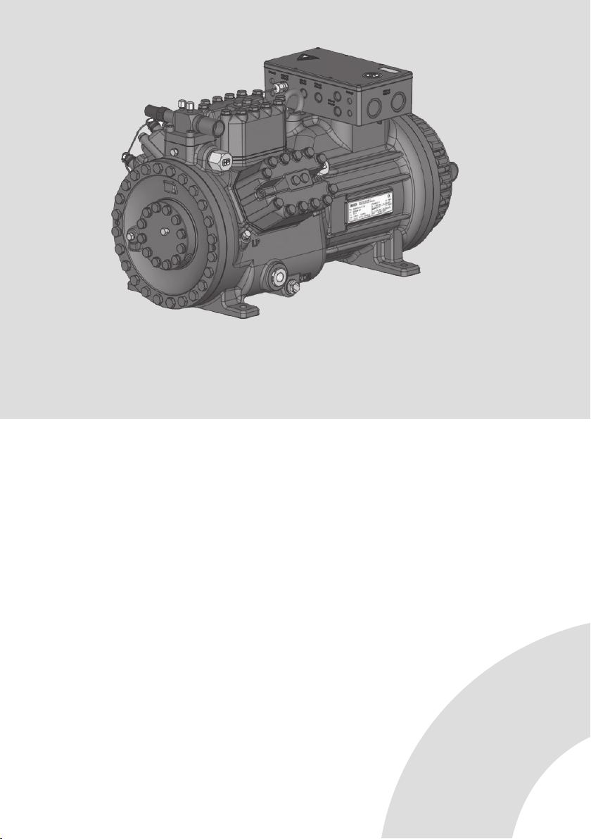
BOCK HGX46 CO2T
Assembly instructions
96460-05.2022-Gb
Translation of the original instructions
BOCK®colour the world
of tomorrow
HGX46/280-4 ML CO2 T HGX46/280-4 S CO2 T HGX46/280-4 SH CO2T
HGX46/310-4 ML CO2 T HGX46/310-4 S CO2 T HGX46/310-4 SH CO2T
HGX46/345-4 ML CO2 T HGX46/345-4 S CO2T HGX46/345-4 SH CO2T
HGX46/440-4 ML CO2T
HGX46/280 MLP 33 CO2T HGX46/280 SP 46 CO2T HGX46/280 SHP 46 CO2T
HGX46/310 MLP 37 CO2T HGX46/310 SP 49 CO2T HGX46/310 SHP 49 CO2T
HGX46/345 MLP 41 CO2T HGX46/345 SP 50 CO2T HGX46/345 SHP 50 CO2T
HGX46/440 MLP 53 CO2T

2
D
GB
F
E
96460-05.2022-DGb
1 Safety 4
1.1 Identicationofsafetyinstructions
1.2 Qualicationsrequiredofpersonnel
1.3 Safetyinstructions
1.4 Intendeduse
2 Product description 6
2.1 Shortdescription
2.2 Nameplate
2.3 Typekey
2.4 TypekeycompressorswithLSPMMotor(Line StartPermanentMagnet)
Contents Page
About these instructions
Manufacturer
Contact
Readtheseinstructionsbeforeassemblyandbeforeusingthecompressor.Thiswillavoidmisunder-
standings andpreventdamage.Improperassemblyanduseofthecompressorcanresultinserious
orfatalinjury.
Observethesafetyinstructionscontainedintheseinstructions.
Theseinstructionsmustbepassedontotheendcustomeralongwiththeunitinwhichthecompres-
sorisinstalled.
BockGmbH
72636Frickenhausen
BockGmbH
Benzstraße7
72636Frickenhausen
Germany
Telephone +4970229454-0
Fax +4970229454-137
www.bock.de

D
GB
F
E
3
96460-05.2022-DGb
Contents Page
3 Areas of application 8
3.1 Refrigerants
3.2 Oilcharge
3.3 Limitsofapplication
4 Compressor assembly 9
4.1 Storageandtransportation
4.2 Settingup
4.3 Connectingthepipelines-soldersystem
4.4 Connectingthepipelines-cuttingringsystem
4.5 Pipes
4.6 Flangeshut-offvalves(HP/LP)
4.7 Layingsuctionandpressurelines
4.8 Operatingtheshut-offvalves
4.9 Operatingmodeofthelockableserviceconnections
4.10 Oilreturn
4.11 Suctionpipelter
5 Electrical connection 14
5.1 Informationforcontactorandmotorcontactorselection
5.2 Standardmotor,designedfordirectorpartwindingstart
5.3 Basiccircuitdiagramforpartwindingstart
5.4 Specialmotor:designfordirectorstar-deltastart
5.5 Basiccircuitdiagramforstar-deltastartwithspecialmotor
5.6 ElectronictriggerunitINT69G
5.7 ConnectionoftheelectronictriggerunitINT69G
5.8 FunctionaltestoftheelectronictriggerunitINT69G
5.9 Oilsumpheater
5.10 Selectionandoperationofcompressorswithfrequencyconverters
6 Commissioning 24
6.1 Preparationsforstart-up
6.2 Pressurestrengthtest
6.3 Leaktest
6.4 Evacuation
6.5 Refrigerantcharge
6.6 Start-up
6.7 Pressureswitch
6.8 Decompressionvalves
6.9 Avoidingslugging
6.10 Filterdryer
7 Maintenance 28
7.1 Preparation
7.2 Worktobecarriedout
7.3 Sparepartsrecommendation/Accessories
7.4 Lubricants/oil
7.5 Decommissioning
8 Technical data 30
9 Dimensions and connections 34
10 Declaration of installation 36
11 Service 37
4
D
GB
F
E
96460-05.2022-DGb
1|Safety
1.1 Identication of safety instructions:
1.2 Qualications required of personnel
WARNING Inadequately qualied personnel poses the risk of accidents, the
consequence being serious or fatal injury. Work on compressors
must therefore only be performed by personnel with the
qualications listed below:
•For example, a refrigeration technician, refrigeration mechatronics
engineer. As well as professions with comparable training, which
enablepersonneltoassemble,install,maintainandrepairrefrigeration
andair-conditioningsystems.Personnelmustbecapableofassessing
theworktobecarriedoutandrecognisinganypotentialdangers.
DANGER Indicates a dangerous situation which, if not avoided, will cause
immediate fatal or serious injury
WARNING Indicates a dangerous situation which, if not avoided, may cause
fatal or serious injury
CAUTION Indicates a dangerous situation which, if not avoided, may imme-
diately cause fairly severe or minor injury.
ATTENTION Indicates a situation which, if not avoided, may cause property
damage
INFO Important information or tips on simplifying work
D
GB
F
E
5
96460-05.2022-DGb
1|Safety
1.3 Safety instructions
WARNING Risk of accident.
Refrigerating compressors are pressurised machines and therefore
require particular caution and care in handling.
The maximum permissible overpressure must not be exceeded,
even for testing purposes.
Risk of burns!
- Depending on the operating conditions, surface temperatures of
over 60 °C on the pressure side or below 0 °C on the suction side
can be reached.
- Avoid the contact with refrigerant under any circumstances.
The contact with refrigerant can lead to severe burns and skin
irritations.
Danger of suffocation.
CO2 is a nonammable, acidic, colourless and odourless gas and
heavier than air.
Never release signicant volumes of CO2or the entire contents of
the system into closed rooms!
Safety installations are designed or adjusted in accordance with EN
378-2 or appropriate safety standards.
• Therefore, we expressly point out that all information in this
assembly instruction has been provided according to our current
level of knowledge and may change due to further development.
Legal claims based on the correctness of the information cannot
be made at any time and are hereby expressly excluded.
Compressors with LSPM Motor:
When the compressor is open, there is danger from a strong mag-
netic eld.
See also Chapter 7, Maintenance.
These assembly instructions describe the standard version of the compressors named in the ti-
tle manufactured by Bock. Bock refrigerating compressors are intended for installing in a
machine (within the EU according to the EU Directives 2006/42/EC Machinery Directive and
2014/68/EUPressureEquipmentDirective).
Commissioningisonlypermissibleifthecompressorshavebeeninstalledinaccordancewiththese
assemblyinstructionsandtheentiresystemintowhichtheyareintegratedhasbeeninspectedand
approvedinaccordancewithlegalregulations.
ThecompressorsareintendedforusewithCO2intranscriticaland/orsubcriticalsystemsincompli-
ancewiththelimitsofapplication.
Onlytherefrigerantspeciedintheseinstructionsmaybeused.
Any other use of the compressor is prohibited!
1.4 Intended use
WARNING The compressor may not be used in potentially explosive
environments!
6
D
GB
F
E
96460-05.2022-DGb
2|Product description
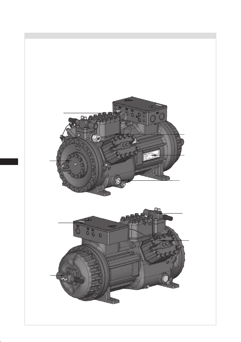
Fig.1
Fig.2
2.1 Short description
• Semi-hermeticsix-cylinderreciprocatingcompressorwithsuctiongascooleddrivingmotor.
• Theowofrefrigerantsuckedinfromtheevaporatorisledovertheengineandprovidesfora
particularlyintensivecooling.Thustheenginecanbekeptonarelativelylowtemperaturelevel
speciallyduringhighload.
• Oilpumpindependentofdirectionofrotationforreliableandsafeoilsupply.
• Onedecompressionvalveeachonthelowandhighpressureside,whichventintotheatmos-
pherewheninadmissiblyhighpressurelevelsarereached.
Oilsightglass
Valveplate
Cylinder
cover
Transporteyelet
Oilpump
Discharge
shut-offvalve
(accessories)
Nameplate
Suction
shut-offvalve
(accessories)
Terminalbox
Dimensionandconnectionvaluescanbefoundinchapter9
D
GB
F
E
7
96460-05.2022-DGb
50 Hz
60 Hz
}
}
Fig.3
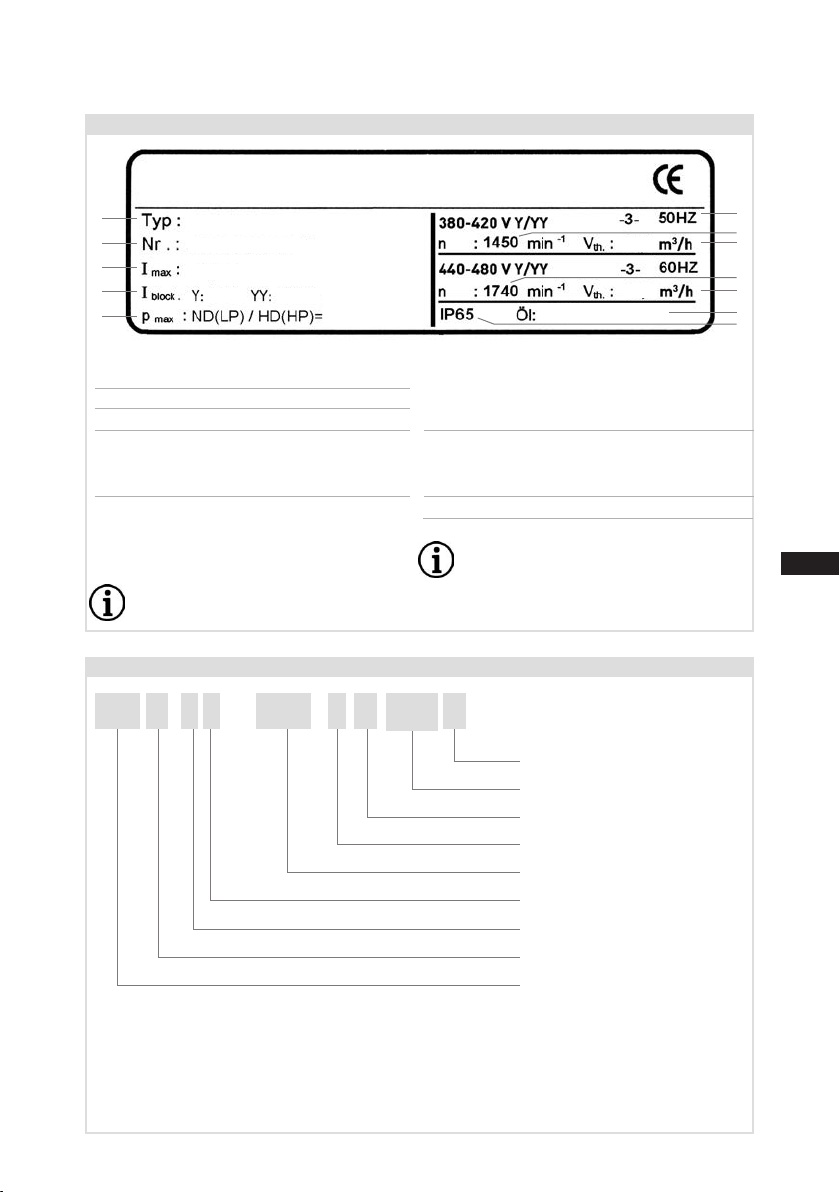
2.2 Name plate(example)
/
HG 46345-4CO2
X
2.3 Type key(example)
T
S
1 Typedesignation
2 Machinenumber
3 Maximumoperatingcurrent
4 Startingcurrent(rotorblocked)
Y:Partwinding1
YY:Partwinding1and2
5 ND(LP):max.permissibleoperating
pressure(g)Lowpressureside
HD(HP):
max.permissibleoperating
pressur
e(g)Highpressureside
Observe the limits of
application diagrams!
6 Voltage,circuit,frequency
7 Nominalrotationspeed
8 Displacement
9 Voltage,circuit,frequency
10 Nominalrotationspeed
11 Displacement
12 Oiltypelledatthefactory
13 Terminalboxprotectiontype
Electrical accessories can change
the IP protection class!
Transcritical
CO2version
Compressorversion³)
Numberofpoles
Sweptvolume
Numberofcylinders
Size
Oilcharge²)
Series¹)
¹)HG - HermeticGas-Cooled(suctiongas-cooled)
²)X - Esteroilcharge
³) ML - Normalcoolinganddeepfreezingatlowandmediumevaporationtemperatures
S - Forfrequencyregulationandextendedlimitsofapplication
SH - Forhighevaporatingtemperatureseg.heatpumps,differentoilcharge
2|Product description
1
2
3
4
5
6
7
8
9
10
11
12
13
BC12345-001
90,9 A
222 A 361 A
30,2
36,2
HGX46/345-4 S CO2T
100/150 bar
Bock GmbH, Benzstraße 7
72636 Frickenhausen, Germany
BOCK
BOCKlub E85

8
D
GB
F
E
96460-05.2022-DGb
Thecompressorsarelledatthefactorywiththefollowingoiltype:
Compressorversion ML(P) and S(P): BOCK lubE85
Compressorversion SH(P): BOCK C170E
(only this oils may be used)
3.1 Refrigerants
• CO2: R744 (Recommendation CO2 quality 4.5 (< 5 ppm H2O))
3.2 Oil charge
ATTENTION Property damage possible.
The oil level must be in the
visible part of the sight glass;
damage to the compressor
is possible if overfilled or
underfilled! Fig.4
Max.
Min.
1.0Ltr.
Oillevel ~
~
3|Areas of application
/
HG 46345 CO2
X
2.4 Type key compressors with LSPM Motor (example)
¹)HG - HermeticGas-Cooled(suctiongas-cooled)
²)X - Esteroilcharge
³) MLP- Normalcoolinganddeepfreezingatlowandmediumevaporationtemperatures
SP - Forfrequencyregulationandextendedlimitsofapplication
SHP- Forhighevaporatingtemperatureseg.heatpumps,differentoilcharge
Transcritical
CO2version
MotorpowerinHP
LSPMMotor
Compressorversion³)
Sweptvolume
Numberofcylinders
Size
Oilcharge²)
Series¹)
50 T
S P
2|Product description
D
GB
F
E
9
96460-05.2022-DGb
ATTENTION Compressor operation is possible within the operating limits
shown in the diagrams. Please note the signicance of the
shaded areas. Thresholds should not be selected as design or
continuous operation points.
- Permissible ambient temperature (-20 °C) - (+60 °C).
- Max. permissible discharge end temperature 160 °C.
- Min. discharge end temperature ≥50 °C.
- Min. oil temperature ≥ 30 °C.
- Max. permissible switching frequency 12x /h.
- A minimum running time of 3 min. steady-state condition
(continuous operation) must be achieved.
Avoid continuous operation in limit range.
3.3 Limits of application
3|Areas of application
4|Compressor assembly
INFO New compressors are factory-lled with inert gas. Leave this
service charge in the compressor for as long as possible and prevent
the ingress of air.
Immediately after refrigeration technological connection of
the compressor close the shut-off devices in suction-, dis-
charge-, oil return line etc. and evacuate the compressor.
Check the compressor for transport damage before starting any
work.
?
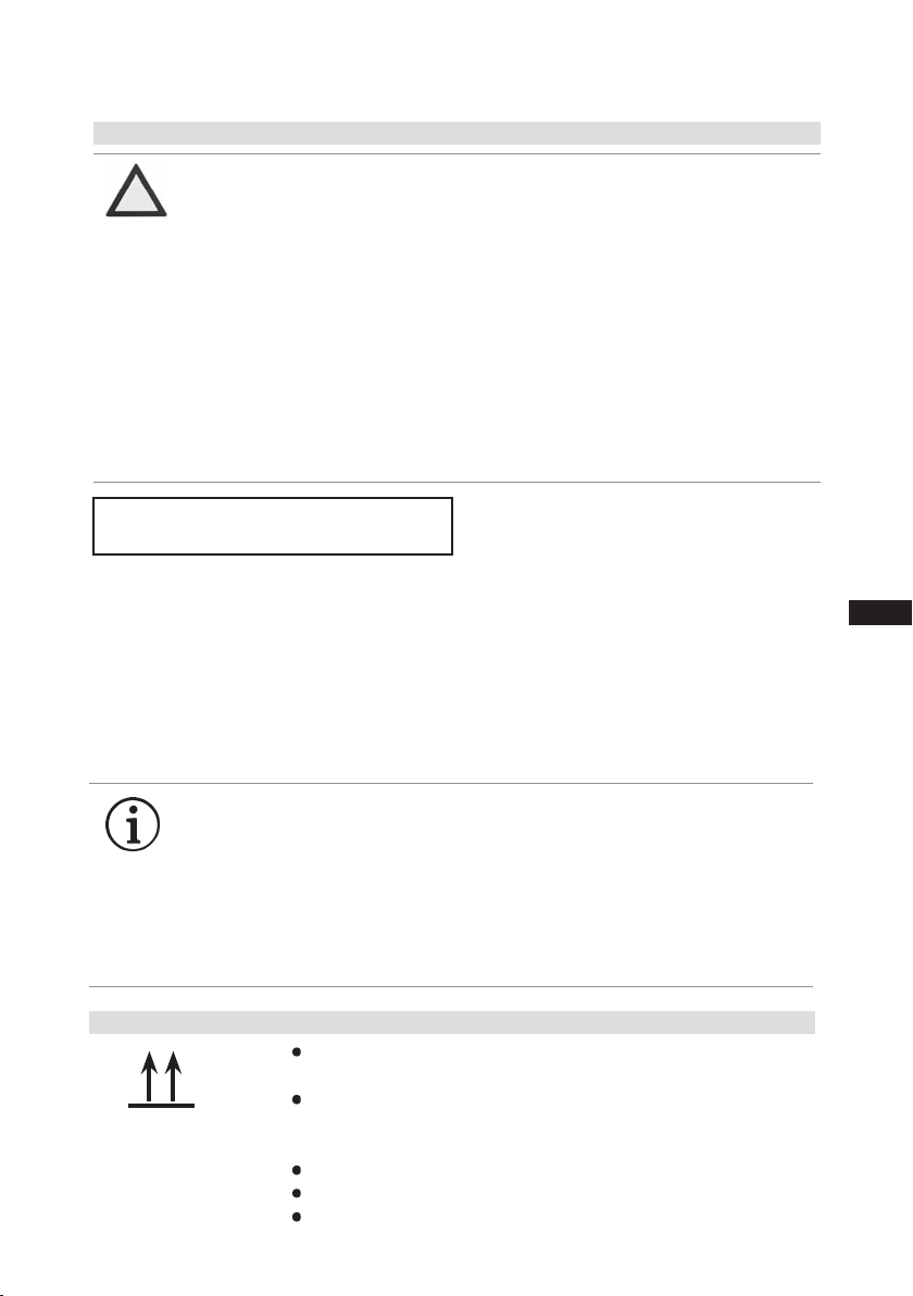
4.1 Storage and transportation
Usetransporteyelet.
Donotliftmanually!
Useliftinggear!
Storageat(-30°C)-(+70°C),maximumpermissiblerelativehumidity
10%-95%,nocondensation.
Donotstoreinacorrosive,dusty,vaporousatmosphereorinacom-
bustibleenvironment.
Maximum permissible operating
pressure (LP/HP)1): 100/150 bar
1) LP=Lowpressure
HP=Highpressure
10
D
GB
F
E
96460-05.2022-DGb
4|Compressor assembly
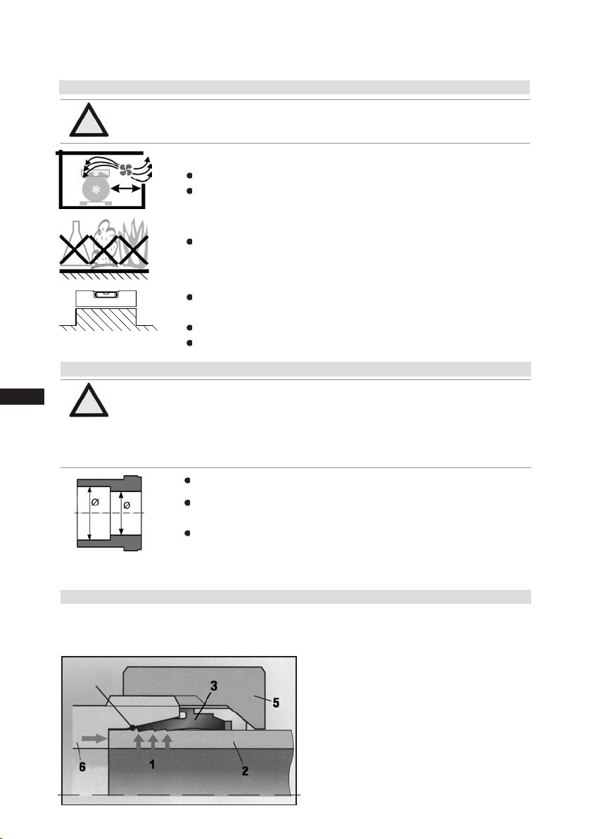
Material soldering / welding connection: S235 (JRG2C)
The pipe connectionshavegraduatedinsidediameterssothatpipeswith
standardmillimetreandinchdimensionscanbeused.
Theconnectiondiametersoftheshut-offvalvesareratedformaximum
compressoroutput.The actual required pipe cross section must be
matched to the output. The same applies for non-return valves.
Fig.5:graduated
internaldiameter
4.3 Connecting the pipelines - solder system
ATTENTION Damage possible.
Superheating can damage the valve.
Remove the pipe supports therefore from the valve for soldering
and accordingly cool the valve body during and after soldering.
Only solder using inert gas to inhibit oxidation products (scale).
•Onitshigh-pressureside,thecompressorhasashut-offvalvewithmulti-sidedcuttingringforsafe
installationofthedischargeline.
Cuttingringfunctionaftertighteningtheunionnut
. . . . .
4.4 Connecting the pipelines - cutting ring system
Fig.6
Figuresimilar
Collar
4.2 Setting up
Setuponanevensurfaceorframewithsufcientload-bearing
capacity.
Singlecompressorpreferablyonvibrationdamper.
Duplexandparallelcircuitsalwaysrigid.
Provideadequateclearanceformaintenancework.
Ensureadequatecompressorventilation.
Donotuseinacorrosive,dusty,dampatmosphereoracom-
bustibleenvironment.
F
E
D
C
B
A
1
2
3
4
F
E
D
C
4
3
2
1
A
B
Tol.-Ang. DIN ISO 2768-mK
Ra Rz
Maß
Passung
Freigabe
Alternativbezug:
Baumustergeprüft
Teil inaktiv
Lieferantenzeichnung
-
-
K.-Auftrag:
PL:
Zeichnung ungültig
Entwicklungsstand
Teil keine Serie
120
400
±0.5
über 0.5
bis 6
Benzstraße 7 - 72636 Frickenhausen - Germany - www.bock.de
-
-
Unbemaßte Radien:
-
Diese Zeichnung ist unser Eigentum!
Sie darf ohne unsere Genehmigung weder nach-
gebildet, vervielfältigt, oder Dritten Personen zu-
gänglich gemacht werden. Der Nachbau nach
dieser Zeichnung, oder an Hand der nach dieser
Zeichnung hergestellten Gegenstände durch den
Abnehmer oder Dritte ist nicht gestattet.
Wir behalten uns alle Rechte, gemäß DIN ISO 16016
an dieser Zeichnung vor.
Bearb.
Datum
Änderungs-Nr.
Werkstoff:
Ausgangsteil, bzw. Rohteil:
--
Gepr.
Name
Datum
19.04.
Werkstückkanten
DIN ISO 13715
Ersatz für:
Ersetzt durch:
Erstellt
2010
Geprüft
-
Kurz
Zone
1/x
Oberflächenbehandlung / Härte:
-
Blatt:
Änderungsbeschreibung
400
Benennung:
±0.8
1000
30
6
-
±0.3
120
30
±0.2
Zeichn.-Nr. Teile-Nr.
Oberflächenangaben ISO 1302
x.xxxx-xxxxx.x
Zust.
Gußtoleranzen:
Gewicht: (kg)
±0.1
Maßstab:
1:1
Wasserwaage
für Indesign
Der Lieferant muß sicherstellen, dass die Ware in
einwandfreiem Zustand angeliefert wird (Korrosions-
schutz, Verpackung für sicheren Transport).
Rz 25
Rz 160
s
25
z
y
x
w
u
t
0,05
Rz 1,6
0,3
0,7
1,6
2
Rz 16
6,3
Rz 63
Rz 6,3
Rz 12,5
F:\user\kurz\3D Sachen\3D Teile\Zeichnungen\Wasserwaage
ATTENTION Attachments (e.g. pipe holders, additional units, fastening parts,
etc.) directly to the compressor are not permissible!

D
GB
F
E
11
96460-05.2022-DGb
AB
Fig.7 Fig.8
4.6 Flange shut-off valves (HP/LP)
CAUTION Risk of injury.
The compressor must be depressurized through connections A
and B before commencing any work and prior to connecting to the
refrigerant system.
4|Compressor assembly
Tube preparation:
Thetubehastobesawninarightangle.Anangulartoleranceof±1°ispermissible.
Slightlytrimthepipeendsinsideandoutside.Forthinwalledsteelpipesorsoftpipesmadeof
nonferrousmetal,reinforcingsleeveshavetobeused.
Pipe assembly:
Pushunionnut(5)andcuttingring(3)ontopipe(2).Insertpipeintosocket(6)asfarasitwillgoand
firmly press against pipe stop, otherwise incorrect assembly. Hand tighten union nut until socket,
cuttingringandunionnut arelocked.Tightenunionnut11/2turnsusinga spannerwrench.The
cutting ring is noticeably locked to the socket face (for assembly inside pipe connection, hold up
valvewithaspannerwrench).Thisshouldcausethecuttingringwithitscuttingedges(1)tocutinto
thepiperesultinginavisiblecollar.Inordertosticktotheturnswerecommendusingmarkinglines
onunionnutandpipe.Afterassembly,itisnecessarytocheckthecollar.Thegasketmustnotbe
damaged.Atleast80%ofthecuttingfacehastobecovered.Aftercheck-up,screwonandtighten
againasdescribedabove.
4.5 Pipes
Pipesandsystemcomponentsmustbecleananddryinsideandfreeofscale,swarfandlayersof
rustandphosphate.Onlyusehermeticallysealedparts.
Lay pipes correctly. Suitable vibration compensators must be provided to prevent pipes being
crackedandbrokenbyseverevibrations.
Ensureaproperoilreturn.
Keeppressurelossestoanabsoluteminimum.

12
D
GB
F
E
96460-05.2022-DGb
Fig.10 Fig.11
4.7 Laying suction and pressure lines
A rule of thumb: Alwayslaytherstpipesectionstartingfromtheshut-offvalvedownwards and
parallel to the drive shaft.
ATTENTION Property damage possible.
Improperly installed pipes can cause cracks and tears which can
result in a loss of refrigerant.
INFO Proper layout of the suction and pressure lines directly after
the compressor is integral to the smooth running and vibration
behaviour of the system.
4.8 Operating the shut-off valves
Beforeopeningorclosingtheshut-offvalve,releasethevalvespindlesealbyapprox.1/4ofaturn
counter-clockwise.
Afteractivatingtheshut-offvalve,re-tightentheadjustablevalvespindlesealclockwise.
Valve spindle seal
Release Tighten
4|Compressor assembly
Fig.9
Rigid fixed
point
As short as
possible
D
GB
F
E
13
96460-05.2022-DGb
Fig.12
Fig.13
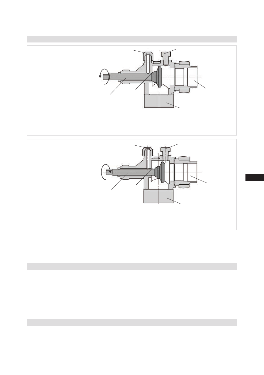
4.9 Operating mode of the lockable service connections
Opening the shut-off valve:
Spindle:turntotheleft(counter-clockwise)asfarasitwillgo.
—>Shut-offvalvecompletelyopened/serviceconnectionclosed.
Theconnectionwhichcannotbeshutoffisintendedforsafetydevices.
Opening the service connection
Spindle:Turn1/2-1turntotherightclockwise.
—>Serviceconnectionopened/shut-offvalveopened.
Theconnectionwhichcannotbeshutoffisintendedforsafetydevices.
Toensuretheoilreturnfunctionwillworkreliablynomatterwhatkindofsystemcongurationyou
areusing,Bockrecommendsincorporatingoilseparatorsoroillevelmonitoringequipment.The"O"
connectionisalreadyavailablefromthefactoryforthepurposeofinstallingtheadditionaloillevel
monitoringcomponent.Oilshouldbereturnedfromtheoilseparatortothecompressorviathe"D1"
connectionprovidedforthispurposeonthecompressor.
For systems with long pipes and higher degree of contamination, a lter on the
suction-sideisrecommended.Thelterhastobebereneweddependingonthedegreeofcontamina-
tion(reducedpressureloss).
4.10 Oil return
4.11 Suction pipe lter
Afteractivatingthespindle,generallytthespindleprotectioncapagainandtightenwith40-50Nm.
Thisservesasasecondsealingfeatureduringoperation.
Pipeconnection
Pipeconnection
Serviceconnec-
tionclosed
Connection
blocked
Spindle
Connectioncannot
beshutoff
Serviceconnec-
tionopened
Spindle Connection
open
Compressor
Compressor
Connectioncannot
beshutoff
4|Compressor assembly
14
D
GB
F
E
96460-05.2022-DGb
5|Electrical connection
5.1 Information for contactor and motor contactor selection
5 Electrical connection
INFO Connectthecompressormotorinaccordancewiththecircuitdiagram
(seeinsideofterminalbox).
Usesuitablecableglandsofthecorrectprotectiontype(seename
plate)forroutingcablesintotheterminalbox.Insertthestrainreliefs
andpreventchafemarksonthecables.
Comparethevoltageandfrequencyvalueswiththedataforthe
mainspowersupply.
Only connect the motor if these values are the same.
DANGER Risk of electric shock! High voltage!
Only carry out work when the electrical system is disconnected
from the power supply!
Allprotectionequipment,switchingandmonitoringdevicesmustcomplywiththelocalsafetyreg-
ulations and established specications (e.g. VDE) as well as the manufacturer’s specications.
Motor protection switches are required!Motorcontactors,feedlines,fusesandmotorprotec-
tion switches must be rated according to the maximum operating current (see name plate). For
motorprotection,useacurrent-dependent,time-delayedoverloadprotectiondeviceformonitoring
allthreephases.Adjusttheoverloadprotectiondevicesothatitmustbeactuatedwithin2hoursat
1.2timesthemaximumworkingcurrent.
For compressors with LSPM motor, a faster responding overload protection device is
recommended.
ATTENTION When attaching accessories with an electrical cable, a minimum
bending radius of 3 x the cable diameter must be maintained for
laying the cable.
D
GB
F
E
15
96460-05.2022-DGb
5|Electrical connection
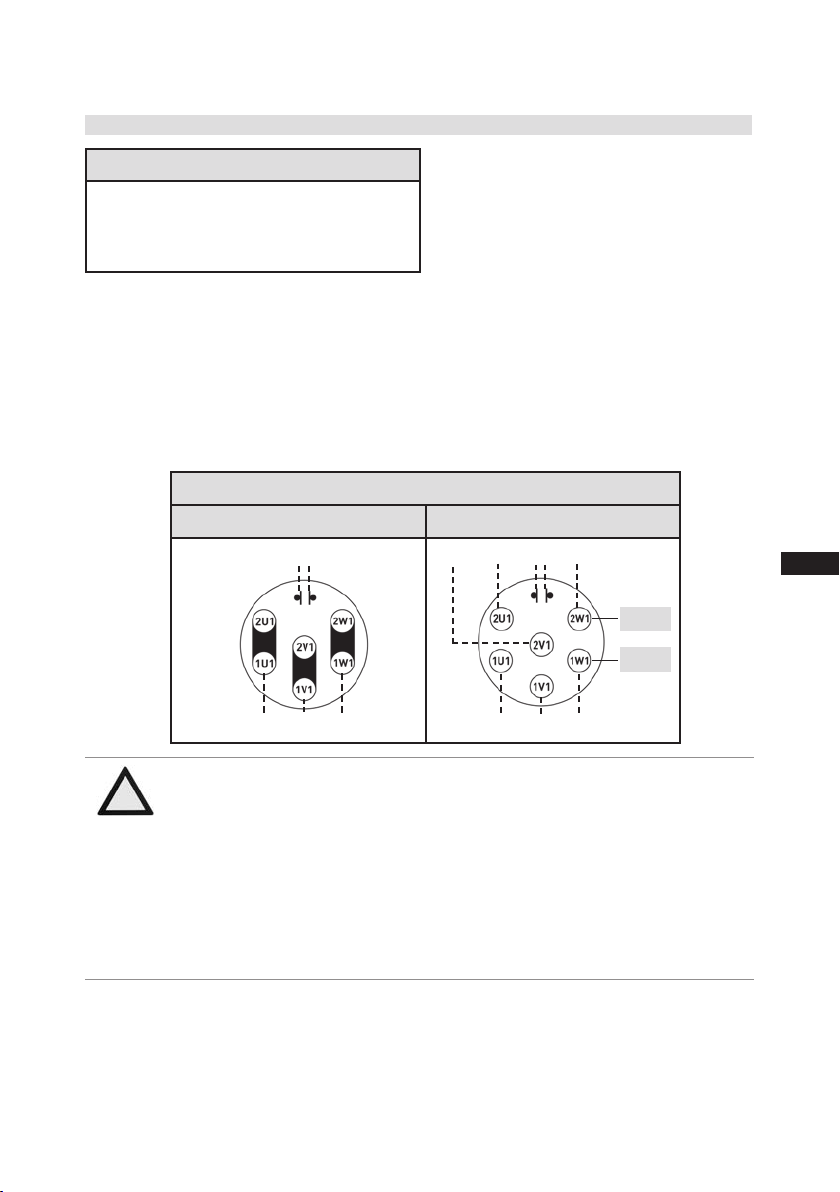
5.2 Standard motor, designed for direct or part winding start
Designationonthenameplate
Y/YY
Compressors markedin thisway aresuitablefordirectorpartwinding start.Themotor windingis
dividedintotwoparts:partwinding1=50%andpartwinding2=50%.Thiswindingdivisionreduces
thestart-upcurrentduringapartwindingstarttoapprox.50%ofthevalueforadirectstart.
Not possible on compressors with LSPM Motor!
Inthefactory,themotorisswitchedfordirectstarting(YY).Forpartwindingstart(Y/YY),removethe
bridgesandconnectthemotorfeedcableaccordingtothecircuitdiagram:
400 V
Direct start YY Part winding start Y/YY
L1
L2
L3
L1
L2
L3
L1 L3
L2
PTC
PW II
PW I
PTC
ATTENTION Property damage possible.
Failure to comply results in reversed elds of rotation and can cause
motor damage. After the motor has started up with part winding 1,
part winding 2 must be switched on after max. 1 second delay. Fail-
ure to comply can be detrimental to the service life of the motor.
Ensure that power is supplied via QA2 to winding 1 (50 %)
(1U1 / 1V1 / 1W1) and via QA3 to winding 2 (50 %) (2U1 / 2V1 / 2W1).
The motor contactors (QA2 / QA3) are each to be rated for approx.
50 % of the max. operating current.

16
D
GB
F
E
96460-05.2022-DGb
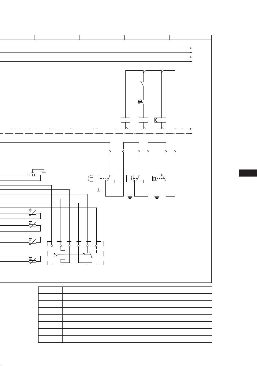
5.3 Basic circuit diagram for part winding start
*Withseveralconnecttheminseries
Fig.14
Οnderung
2
0
Datum Name
Datum
Bearb.
Gepr.
Norm
1
20.02.2009
bauknecht
26.11.2020
Urspr.
2
Ers. f.
3
Ers. d.
4
PW INT69 HG44/66
567
BOCK COMPRESSORS
8
=
+
9
Bl.
6.d Bl.
5.a
2.a
Anschlußkasten Verdichter
BT1
INT69
DELTA- P II
QA1
L1 L2 L3 N PE
FC1.1
I> I>
I>
QA2
1U1
1V1
1W1
PE
EC1
M
Y/YY
2U1
2V1
2W1
FC1.2
I> I>
I>
QA3
FC1.1
FC1.2
FC2
SF1
BP2
P>
QA2
BP3
P
QA2
KF1
KF1
QA2
L1.1
L2.1
L3.1
L1.2
N
PE
QA3
BT4
BT2
Θ
1112 14
L N B1 B2
12
11
10
9
8
7
6
5
4
3
2
1
Θ
vio bn bu gr
Θ
EB1
pk og
21
20
BT3
Θ
50% 50%
Compressorterminalbox
BP2 Highpressuresafetymonitor
BP3 Safetychain(high/lowpressuremonitoring)
BT1 Coldconductor(PTCsensor)motorwinding
BT2 Thermalprotectionthermostat*
BT3 Oiltemperaturesensor
BT4 Releaseswitch(thermostat)
DELTA-PII OildifferentialpressuresensorDELTA-PII(accessory)
EB1 Oilsumpheater
EC1 Compressormotor
D
GB
F
E
17
96460-05.2022-DGb
FC1.1/1.2 Motorprotectionswitch
FC2 Controlpowercircuitfuse
INT69G ElectronictriggerunitINT69G
KF1 Delayrelayforcontactorswitchover
QA1 Mainswitch
QA2 Mainscontactor(partwinding1)
QA3 Mainscontactor(partwinding2)
SF1 Controlvoltageswitch
Οnderung
2
0
Datum Name
Datum
Bearb.
Gepr.
Norm
1
20.02.2009
bauknecht
26.11.2020
Urspr.
2
Ers. f.
3
Ers. d.
4
PW INT69 HG44/66
567
BOCK COMPRESSORS
8
=
+
9
Bl.
6.d Bl.
5.a
2.a
Anschlußkasten Verdichter
BT1
INT69
DELTA- P II
QA1
L1 L2 L3 N PE
FC1.1
I> I>
I>
QA2
1U1
1V1
1W1
PE
EC1
M
Y/YY
2U1
2V1
2W1
FC1.2
I> I>
I>
QA3
FC1.1
FC1.2
FC2
SF1
BP2
P>
QA2
BP3
P
QA2
KF1
KF1
QA2
L1.1
L2.1
L3.1
L1.2
N
PE
QA3
BT4
BT2
Θ
1112 14
L N B1 B2
12
11
10
9
8
7
6
5
4
3
2
1
Θ
vio bn bu gr
Θ
EB1
pk og
21
20
BT3
Θ

18
D
GB
F
E
96460-05.2022-DGb
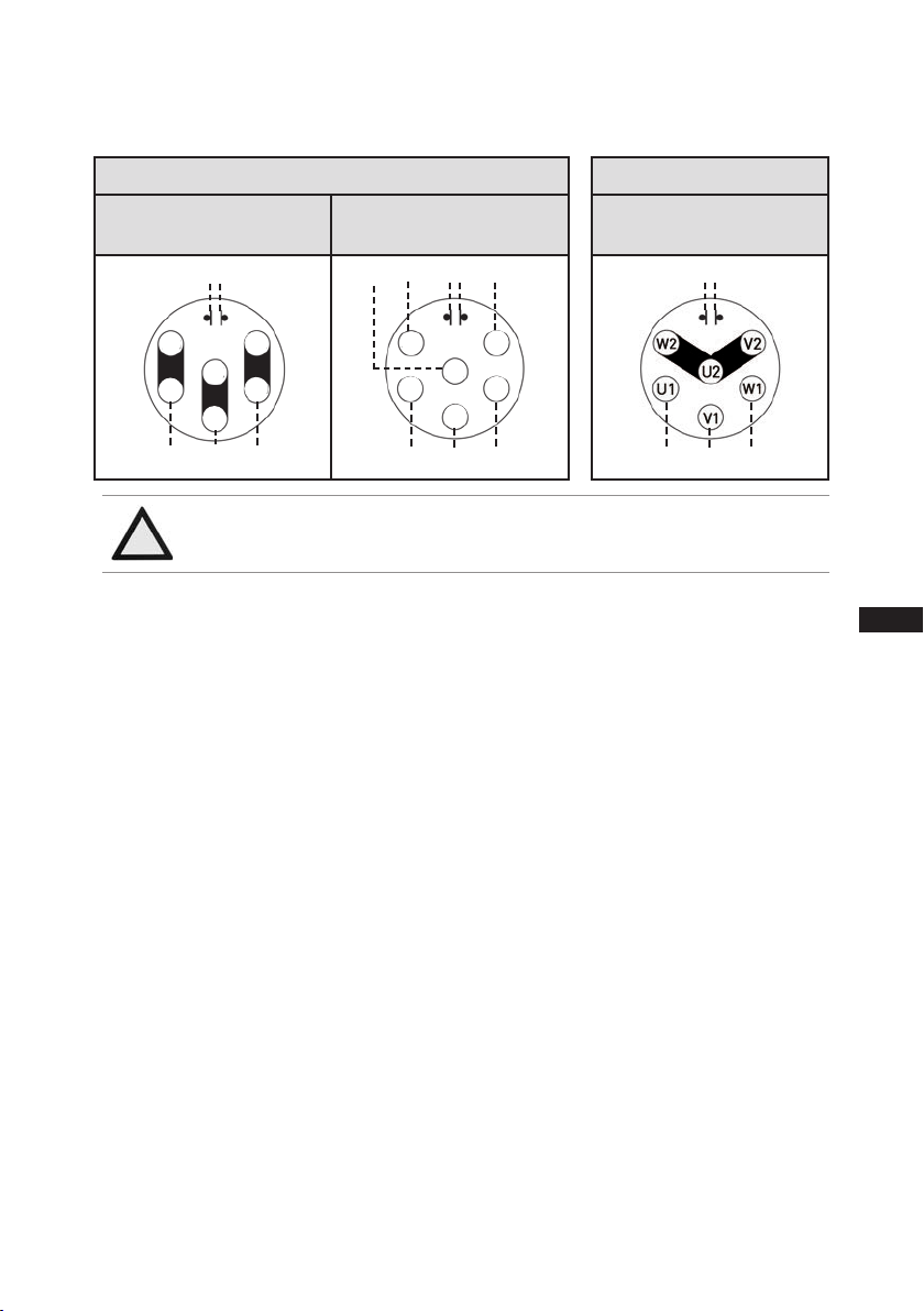
5.4 Special motor: design for direct or star-delta start
5|Electrical connection
Designationonthenameplate
∆/ Y
D
GB
F
E
19
96460-05.2022-DGb
5|Electrical connection
Star-delta start-up is only possible for 230 V power supply. Example:
400 V Y
Direct start only
L1 L3
L2
PTC
230 V Δ
Direct start Star-delta start
(not on LSPM Motor)
L1
L2
L3
L1
L2
L3
L1 L3
L2
PTC PTC
W2
U2
V2
W1
U1
V1
W2
U2
V2
W1
U1
V1
Only direct start is possible with LSPM Motor.

20
D
GB
F
E
96460-05.2022-DGb
5.5 Basic circuit diagram for star-delta start with special motor
*Withseveralconnecttheminseries
Fig.15
Οnderung
4
0
Datum Name
Datum
Bearb.
Gepr.
Norm
1
20.02.2009
bauknecht
03.11.2020
Urspr.
2
Ers. f.
3
Ers. d.
4
D/S INT69 HG44/66 neu
567
BOCK COMPRESSORS
8
=
+
9
Bl.
6.d Bl.
6.b
6.a
Anschlußkasten Verdichter
BT1
INT69G
DELTA- P II
QA1
L1 L2 L3 N PE
U1
V1
W1
PE
U2
V2
W2
FC1.1
FC1.2
FC2
SF1
BP2
P>
BP3
P
QA2
L1.1
L2.1
L3.1
L1.2
N
PE
BT4
BT2
Θ
1112 14
L N B1 B2
12
11
10
9
8
7
6
5
4
3
2
1
Θ
vio bn bu gr pk og
Θ
EB1
FC1.1
I> I>
I>
1
2
QA2
FC1.2
I> I>
I>
3
4
5
6
1
2
QA4
Y
3
4
5
6
1
2
QA3
D
3
4
5
6
EC1
M
3˜
QA2
QA2
QA4 KF1
QA4
QA3
KF1
QA3
QA4 KF1
20
21
BT3
Θ
Compressorterminalbox
BP2 Highpressuresafetymonitor
BP3 Safetychain(high/lowpressuremonitoring)
BT1 Coldconductor(PTCsensor)motorwinding
BT2 Thermalprotectionthermostat (PTCsensor)*
BT3 Oiltemperaturesensor
BT4 Releaseswitch(thermostat)
DELTAPII OildifferentialpressuresensorDELTA-PII(accessory)
EB1 Oilsumpheater
EC1 Compressormotor
This manual suits for next models
20
Table of contents
Other BOCK Industrial Equipment manuals


Popular Industrial Equipment manuals by other brands

GFA ELEKTROMATEN
GFA ELEKTROMATEN SG 85F installation instructions

A.B.S.
A.B.S. Flexilo TROUGH Assembly-, Operating-, and Filling Instructions

Berker
Berker RolloTec 2911 operating instructions

Tisch Environmental
Tisch Environmental TE-5170-BL Operation manual

Telesis
Telesis BenchMark 320 manual

HEIDENHAIN
HEIDENHAIN ECN 413 Mounting instructions


