Telesis BenchMark 320 User manual
BenchMark 320/BM470 Marking System
34753A ©2020 Telesis Technologies, Inc. –All Rights Reserved 1of 10
Disclaimer: Printed or downloaded copies of this document are considered to be uncontrolled. Documentation is subject to change without
notice.
SYSTEM OVERVIEW
The Telesis®BenchMark®320 marking system
permanently prints messages into materials such as
steel, aluminum, and plastic. An electric solenoid
accelerates a hardened pin to indent dot matrix
characters into the item being marked. Character
shape, size, density, and location are determined by
the user through the marking system software.
Marking Head.The BenchMark 320 marking head
is an electromechanical marker. A thermoformed
cover houses the internal, mechanical components
that position the pin cartridge and fire the marking
pin. A spring returns the pin to its idle position
within the cartridge. The marking head moves the
pin cartridge through X- and Y-axis motions to
reach the correct position for each dot of the
characters to be marked. The system software
controls pin extension to mark the message.
The marker’s two stepper-motor drives rapidly and
accurately position the pin at coordinate-defined
locations in the marking window within 0.032 mm
(0.00125 inch). The marker accommodates the
rigorous dynamics of impacting, rebounding, and
rapid positioning of the marking pin through a
system of rigid rails and ball bearing saddles, timing
belts, and direct-drive, toothed pulleys.
The pin design permits high-quality, consistent
marks on irregular, slightly curved surfaces. It also
accommodates applications where marking surfaces
cannot be positioned at a consistent distance from
the marker.
The unique design of the BenchMark 320 provides
liberal access for securing and positioning parts for
printing. Using a gantry arm and a programmable
Park position, you can tuck the impact pin out of the
way when the marker finishes printing. Parts can be
easily secured and removed in front of the marking
head.
Marker Cable.The marker cable connects the
marker to the BM470 controller. The cable is 4 m
(13 feet) and is prewired to the marking head.
Pin Cartridge. The pin cartridge is machined from
engineered plastic materials and offers long life with
little maintenance. Screws attach the pin cartridge
to the marking head for easy removal, cleaning, and
pin replacement.
Marking Pins. The 25XLE-series marking pins are
made of tungsten carbide and are available in 30°
and 45° cone angles.
Controller. The BM470 controller allows full
operational control of the marking head. It contains
an integrated keyboard with an LCD display and
provides a text-only operator interface. The back
panel provides an electrical interface for connecting
optional remote I/O sources. Refer to BM470
Controller Specifications for details.
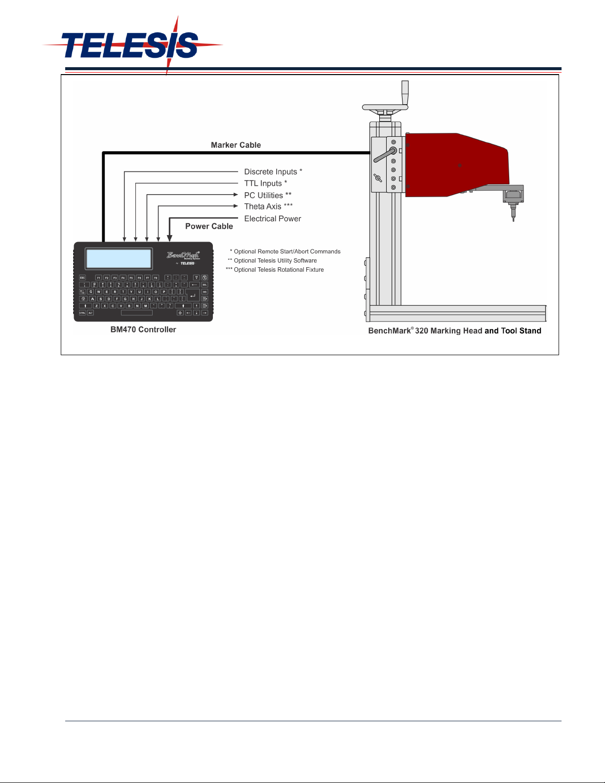
BenchMark320/BM470 Marking System – General Arrangement

BenchMark 320/BM470 Marking System
2of 10 34753A
Tool Stand. The tool stand holds the marking head
and provides a base for securing parts to be
marked. A screw jack with an adjustment wheel
positions the marker above the marking surface.
Adjustment locks secure it in place. The generous
vertical adjustment accommodates parts up to
298.4 mm (11.75 inches) high. The tool stand base
contains slots to accommodate part fixtures. The
tool stand comes with two 8 mm T-nuts to aid in
securing the parts for marking.
SYSTEM OPTIONS
·Auxiliary Axis Driver Board Kit
·Motorized Theta-Axis with Programmable
Rotary Drive Unit
·BM470 Controller Wall-Mounting Bracket Kit
·Barcode Scanner or Barcode Wand with Cable
·Foot Switch (Start Print) or Push Button
Station (Start/Abort)
·Backup Utility Software
·Upgrade Utility Software
·Logo/Font Generator Software
·BM470+ Enhanced Communications Software
SYSTEM SETUP
1. Position the tool stand assembly in the
appropriate location.
2. Mount the marking head to the tool stand
assembly using four M8-1.25 socket head cap
screws.The screws must extend at least 9
mm (0.375 inch) but not more than 12 mm
(0.5 inch) into the back plate. Refer to the
BenchMark 320 Marking Head Dimensions
drawing for details.
CAUTION
The BM470 controller is not a sealed unit.
Protect it from potentially damaging
conditions and contaminants. Do not
block the vents in the bottom of the case.
Ensure the marking system is electrically
isolated from devices that may generate
extreme electromagnetic interference
(EMI).
3. Locate the controller as close as practical to the
marking head. Standard marker cable length is
4 m (13 feet).
4. Ensure the controller power switch on the back
panel is OFF. Connect the power cable to the
controller.
5. Connect the marker cable from the marking
head to the controller, and securely tighten.
6. To start the marking system software, position
the controller power switch on the back panel to
ON.
7. Adjust the pin stroke for proper pin impact
depth.

BenchMark 320/BM470 Marking System
34753A 3of 10
BENCHMARK 320 MARKING HEAD
Specifications
The BenchMark 320 marking head specifications are
subject to change without notice.
Dimensions...................... see the BenchMark 320 Marking
Head Dimensions drawing
Weight
Marker ....................... 5.84 kg (12.865 lb)
Marker & Cable ........... 6.39 kg (14.055 lb)
Tool Stand.................. 16.0 kg (35.200 lb)
Noise (maximum)........... 65.4 dB
59.1 dB (LEQ)
see Marking Noise
Operating Temperature... 0° to 50°C
(32° to 122°F),
non-condensing
Marking Area.................. 150 x 100 mm
(6.0 x 4.0 inches)
Pin Types ....................... 25XLE-series
Pin Material.................... Tungsten Carbide
Marking Characteristics
The BenchMark 320 can accommodate character
sizes from .762 to 100 mm (.030 to 4.0 inches) in
.025 mm (.001-inch) increments. Characters can be
rotated in 1° increments with printing resolutions
from 4 dots/cm (10 dots/inch) to 32 dots/cm
(80 dots/inch) for an engraved look.
Marking Speeds
The system generally marks three characters per
second using 5 x 7 font, 3 mm (.118-inch) high, 2
mm (.080-inch) wide characters. Speeds vary
slightly depending on the selected character size,
style, and dot density. Specific times can be verified
by a Telesis representative.
Marking Noise
Although every attempt is made to reduce noise,
the material being marked significantly influences
the noise level. For example, marking a solid lead
block produces less noise than marking a thin-
walled steel pipe.
Marking Depth
The BenchMark 320 can obtain a marking depth of
.127 mm (.005 inch) in mild steel (Rb53) using a
25XLE carbide pin with a 45° cone angle. The depth
of mark can be adjusted over a significant range by
changing the impact force (via software parameter)
or by changing the impact distance (pin stroke).
Specific depths can be verified by a Telesis
representative.
Pin Life
Pin life depends largely on the type of material
being marked, how hard or abrasive it is, and the
required marking depth. On typical metals with a
hardness of Rockwell Rb47, marking at a depth of
.127 mm (.005 inch), carbide pins average
approximately 9 million impressions before needing
sharpened.

BenchMark 320/BM470 Marking System
4of 10 34753A
BenchMark 320 Marking Head Dimensions

BenchMark 320/BM470 Marking System
34753A 5of 10
BM470 CONTROLLER
Specifications
The BM470 controller specifications are subject to
change without notice.
Compliance .................. CE, RoHS
Rating ......................... NEMA 1 (I. P. 30)
Mounting Configuration.. Tabletop
Dimensions.................... see the BM470 Controller
Dimensions drawing
Weight ........................ 1.68 kg (3.69 lb) controller only
Power Requirements...... 95 to 250 VAC, 2 amps, 50-60
Hz, single phase
Operating Temperature ...0° to 50°C (32° to 122°F),
non-condensing
Operating Humidity ....... 10% to 80% non-condensing
Cooling.......................... Internal, thermostatically
controlled fan
Communications ........... TTL, RS232, and USB*
Input Signals** .............. Two available (Start Print,
Stop/Abort)
10 VDC (minimum voltage)
30 VDC (maximum voltage)
12 to 24 VDC (nominal voltage)
2.3 mA @ 12 VDC;
4.9 mA @ 24 VDC (nominal
current)
**USB for data backup and transfer
** Additional I/O signals available with the optional
BM470+ Enhanced Communications Software
Environmental Considerations
The following environmental considerations must be
taken into account when installing the BM470
controller.
Contaminants. The vented and fan-cooled
controller is rated NEMA 1 (I. P. 30). In
environments where solid or liquid contaminants are
present, the contaminants can be drawn into the
controller and cause the electronic components to
fail. For that reason, in these types of
environments, the controller must be located in a
sealed industrial enclosure.
EMI Susceptibility. Although the system has been
found to be in compliance with pertinent
susceptibility standards, care should be taken when
installing near welders and other extreme
generators of electromagnetic interference (EMI).
Particular care should be taken to ensure welder
currents are not injected through the marking head
chassis. The marking head chassis is connected to
the electrical service earth ground through the
marking head cable. The marking head should be
electrically isolated from all surfaces which could
become part of a welder current path.
Table of contents
Other Telesis Industrial Equipment manuals


