Smipack BP700 User manual

59/282
ENGLISH
Use and maintenance manual ßP700
USE AND MAINTENANCE MANUAL
Film shrink-wrapping machine with sealing bar
ßP700
MANUAL CODE
CREATION DATE
RELEASE:
RELEASE DATE:
DM210087
05.07.2001
6.0
21.11.2005
+
+
+
+
+
+
+
+
+
+
+
+
+
60/282
FOREWORD
In thanking you for the preference given us, SMIPACK S.p.A. is glad to welcome you
to its wide circle of Clients and hopes that the use of this machine satisfies you
completely.
This manual can be used for model ßP700 and was prepared with the aim to allow you
to operate on the various components, explain the various operations for maintenance
and operation.
Where not expressly indicated by the , instructions refer to all the above
mentioned models.
In order to guarantee a satisfactory level of efficiency, life and performance of the
machine, we urge you to scrupulously observe the instructions contained in this
manual.
SMIPACK S.p.A. is absolutely not responsible for any direct or non direct conse
quence due to proper or non proper use of this publication or of the system software
and has got right to make technical modification on his system and on his manual
without advising the users.
SMIPACK S.p.A. - Viale Vittorio Veneto, 4 - 24016 San Pellegrino T. (BG) - Italy - Tel.
+39.0345.40400 - Fax +39.0345.40409
PLEASE READ THIS MANUAL CAREFULLY BEFORE INSTALLING
THE MACHINE.
THIS MANUAL IS AN INTEGRAL PART OF THE PRODUCT AND MUST
ALWAYS ACCOMPANY THE SAME UP TO ITS DISMANTLING.

Dichiarazione di conformità CE
EC Declaration of conformity
Il fabbricante SMIPACK S.p.A., con insediamenti produttivi e uffici amministrativi-direzionali in
Viale Vittorio Veneto, 4 24016 S.Pellegrino Terme (BG) ITALY
The company SMIPACK S.p.A., with production site and head-quarters in Viale Vittorio Veneto,
4 24016 S.Pellegrino Terme (BG) ITALY
dichiara che la macchina
declares that the machine
è conforme alle direttive comunitarie
complies with EC Directives
tipo: Fardellatrice a film termoretraibile con barra
type: Film shrink-wrapper with sealing bar
serie: ßP700
series:
modello:
model:
matricola n.:
serial nr.
anno di costruzione: 2007
year of construction:
98/37/CE
Concernente il riavvicinamento delle legislazioni degli Stati
membri relative alle macchine
On the approximation of the laws of the Member States relating to
machinery
89/336/CEE
92/31/CEE
Compatibilità elettromagnetica
Electromagnetic compatibility
73/23/CEE Bassa tensione
Low voltage

e alle norme armonizzate di buona pratica costruttiva, tra cui:
and with Harmonized Standards:
Il sottoscrittore per l'azienda
The company undersigner
EN 422
Macchine per gomma e materie plastiche - Sicurezza - Macchine per
soffiaggio per la produzione di corpi cavi - Requisiti per la
progettazione e costruzione.
Safety of rubber and plastics machines - Blow moulding machines intend-
ed for the production of hollow articles - Requirements for design and con-
struction
EN ISO 12100-1
Sicurezza del macchinario. Concetti fondamentali, principi generali
di progettazione. Terminologia di base.
Safety of machinery. Basic concepts, general principles for design. Basic
terminology.
EN ISO 12100-2
Sicurezza del macchinario. Concetti fondamentali, principi generali
di progettazione. Specifiche e principi tecnici.
Safety of machinery. Basic concepts, general principles for design. Tech-
nical principles and specifications.
EN 294
Sicurezza del macchinario. Distanze di sicurezza per impedire il
raggiungimento di zone pericolose con gli arti superiori.
Safety of machinery. Safety distances to prevent danger zones from being
reached by the upper limbs.
EN 349
Sicurezza del macchinario. Spazi minimi per evitare lo
schiacciamento del corpo.
Safety of machinery. Minimum gaps to avoid crushing of parts of the hu-
man body.
EN 60204-1
Sicurezza del macchinario. Equipaggiamento elettrico delle
macchine. Parte 1: regole generali.
Safety of machinery. Electrical Equipment of Machines. Part 1: General
rules.
EN 60439-1
Apparecchiature assiemate di protezione e manovra per bassa
tensione (quadri B. T.)
Low voltage switchgear and controlgear assemblies (Low voltage panels)
Nome: Giuseppe
Name:
Cognome: Nava
Surname:
Funzione Legale Rappresentante
Charge: Legal Representative
San Pellegrino Terme, ..........................................................
Data\date Firma\signature

63/282
ENGLISH
Use and maintenance manual ßP700
CONFORMITY STATEMENT ...................................................................................................... 61
1. REGULATIONS AND GENERAL INSTRUCTIONS ......................... 65
1.1. HOW TO CONSULT AND USE THIS MANUAL ................................................................. 65
1.2. WARRANTY CONDITIONS ............................................................................................... 65
1.3. LEGAL REFERENCES ...................................................................................................... 66
1.4. REMARKS ON GENERAL SAFETY .................................................................................. 66
1.5. LEGEND ............................................................................................................................. 67
2. MACHINE INSTALLATION .............................................................. 69
2.1. DESCRIPTION OF THE MACHINE ................................................................................... 69
2.2. WEIGHT AND DIMENSIONS OF THE PACKED MACHINE ............................................. 69
2.3. WEIGHT AND DIMENSIONS OF THE MACHINE ............................................................. 70
2.4. TRANSPORT AND UNPACKING ...................................................................................... 70
2.5. POSITIONING AND LEVELLING ....................................................................................... 71
2.6. ADJUSTING THE CONNECTION BELT AND FASTENING .............................................. 71
2.7. DEMOLITION AND DISPOSAL .......................................................................................... 71
2.8. ELECTRICAL CONNECTIONS .......................................................................................... 71
2.9. TECHNICAL DATA FOR THE ELECTRIC CONNECTION ................................................ 72
2.10. CONDITIONS OF USE ....................................................................................................... 72
3. INFORMATION ON THE MACHINE ................................................. 73
3.1. OPERATING FEATURES OF THE MACHINE ................................................................... 73
3.2. MACHINE IDENTIFICATION ............................................................................................. 73
3.3. MAXI. PRODUCT DIMENSIONS ....................................................................................... 73
3.4. SHRINK-WRAPPING FILM CHARACTERISTICS ............................................................. 73
3.5. DATA FOR THE PNEUMATIC INSTALLATION ................................................................. 74
3.6. FIRST FILM SEALING ....................................................................................................... 74
4. PREPARATION TO THE USE OF THE MACHINE .......................... 75
4.1. MACHINE START-UP ....................................................................................................... 75
4.2. CHOOSING THE OPERATING MODE .............................................................................. 75
4.3. MANUAL SELECTION ....................................................................................................... 76
4.4. AUTOMATIC SELECTION ................................................................................................. 76
4.5. EMERGENCY PUSH-BUTTON ......................................................................................... 76
4.6. QUICK SELECTION OF THE PROGRAMS ....................................................................... 76
4.7. STORING PROGRAMS AND MODIFICATIONS ............................................................... 77
4.8. PARAMETERS MENU (F3+) .............................................................................................. 79
4.9. SYMBOLS AND DISPLAY MESSAGES LEGEND ............................................................ 80
5. MACHINE USE ................................................................................. 81
5.1. INTENTED USE ................................................................................................................. 81
5.2. PACKING WITH THE SEMIAUTOMATIC MACHINE ßP700 ............................................ 81
5.3. CHECKING FOR GOOD OPERATING CONDITIONS ...................................................... 82
5.4. MACHINE LIMITATIONS AND SPECIFICATIONS OF USE .............................................. 82
5.5. DANGEROUS AREAS ....................................................................................................... 82
SUMMARY

64/282
Summary
6. SETTINGS AND ENTRY RECORDINGS ......................................... 83
6.1. ADJUSTING THE FEEDING BAR’S ROD .........................................................................83
6.2. ADJUSTING THE FILM WINDING ROLLER ......................................................................83
6.3. ADJUSTING THE FILM TENTION .....................................................................................83
6.4. ADJUSTING THE PRESS ..................................................................................................84
7. MAINTENANCE AND REPAIRS ...................................................... 85
7.1. NATURE AND FREQUENCY OF MAINTENANCE CHECKS AND
OPERATIONS ........................................................................................................85
7.2. CLEANING AND CHECKING THE SEALING GROUP ......................................................88
7.3. BLADE REPLACEMENT ....................................................................................................88
7.4. REPLACING SILICONE RUBBER AND SPRINGS OF THE SEALING CONTRAST UNIT ... 89
7.5. REPLACING THE COMPONENTS OF THE SEALING BAR .............................................90
7.6. LIST OF SPARE PARTS ....................................................................................................91
MH230000 ..........................................................................................................................91
MH250003 ....................................................................................................................92
MH250002 ..........................................................................................................................93
MH250004 ..........................................................................................................................94
MY330000 ..........................................................................................................................95
MY340002 ..........................................................................................................................96
MY380001 ..........................................................................................................................97
MH220001 ..........................................................................................................................98
MH220002 ..........................................................................................................................99
MH220003 ........................................................................................................................100
MG490144 ........................................................................................................................101
MY390003 ........................................................................................................................102
MH220004 ........................................................................................................................103
7.7. WIRING DIAGRAM ...........................................................................................................104
8. ANOMALIES AND FAILURES - HOW TO REMEDY ..................... 109
8.1. POSSIBLE CAUSES AND REMEDIES ............................................................................109
8.2. AUDIO WARNING OF PROBLEMS .................................................................................109
INDEX ....................................................................................................... 113

65 / 282
ENGLISH
Use and maintenance manual ßP700
1.1 HOW TO CONSULT AND USE THIS MANUAL
Keeping of this manual
• This manual costitutes integral part of the machine and thus must be kept for as long
as the machine is in the user’s possession or, if that be the case, handed over to
any other user or subsequent owner.
• Use this manual in a way that will not damage all or part of its contents.
• Do not remove, tear or rewrite parts of this manual for any reason.
• Ensure that any amendment to this manual sent to you is incorporated in the manual
itself.
Consultation of the manual
The consultation of this manual is made easy be the insertion, in the first pages, of a
summary, which allows those consulting it to immediately locate the topic required and,
in the last pages, of an analytical index. The chapters are ordered following such a
structure to facilitate the research of the required information.
Method of updating the manual in case of modifications to the machine
The descriptions and drawings contained in the present manual are intended as non
refutative. SMIPACK S.p.A. reserves the right at any moment to apport modifications
to its machines (while keeping their essential characteristics), for the purpose of
improving their functionality and commercial and aestethic value, with no obligation to
update manuals and previous production except in exceptional cases.
Any updating or integration of the manual are to be considered as integral parts of the
manual. We would like to thank you in advance for all the suggestions that you may
want to forward to us in order to bring about further improvements to the machine.
SMIPACK S.p.A. - Viale Vittorio Veneto, 4 - 24016 San Pellegrino T. (BG) - Italy - Tel.
+39.0345.40400 - Fax +39.0345.40409
1.2 WARRANTY CONDITIONS
The machine is sent to the Client ready to be installed, and having passed, at our
factory, all expected tests and trials, in compliance with the current regulations. Within
the guarantee period SMIPACK S.p.A. undertakes to remove any eventual flaws and
defects, on the condition that the machine has been correctly used, and that the
indications found in its manuals have been respected. The warranty has a validity of
365 days from the date of purchase and covers all the materials and manufacturing
defects found by the builder.
The warranty is valid only for the original buyer and subject to the condition that the
warranty certificate is duly filled in all its sections and posted within 20 days from the
date of purchase. The warranty is no longer valid if the machine has been damaged
through accident, misuse, breakdowns due to atmospheric agents, maintenance
operations or modifications carried out by unauthorised personnel or not belonging to
the servicing department of SMIPACK S.p.A. Consumption materials, parts subject to
normal wear and tear, transport from the user to the servicing centre or vice-versa as
well as labour are excluded from the warranty and therefore are to be paid by the Buyer
1. REGULATIONS AND GENERAL INSTRUCTIONS

66 / 282
1. Regulations and general instructions
1.3 LEGAL REFERENCES
The machine "Film shrink-wrapper with sealing bar" complies to the Legislative
Provisions of the law that regulates the following Directives:
• MACHINE DIRECTIVE: 89/392/CEE, 91/368/CEE, 93/44/CEE, 93/68/CEE, 98/37/
CE.
• ELECTROMAGNETIC COMPATIBILITY DIRECTIVE: 89/336/CEE, 92/31/CEE,
and 93/97/CEE.
• LOW TENSION DIRECTIVE: 73/23CEE
The directives have been followed considering the agreed norms, including:
• EUROPEAN SAFETY REGULATION FOR MACHINERY:
EN 292/1 - EN 292/2 - EN 292/2/A1 - EN 294 - EN 349.
• ELECTRIC EQUIPMENT OF THE MACHINES: EN 60204-1.
• ASSEMBLED PROTECTION EQUIPMENT AND TRANSITION FOR LOW
TENSION (BOARD B.T.): EN 60439-1
1.4 REMARKS ON GENERAL SAFETY
The operator, before starting to work with this machine, must have acquired enough
knowledge on the location, function of the controls, characteristics of the machine, and
must have read this manual in all its entirety.
The employer must see to it that its personnel is informed on the following topics
relative to the safe usage of the machine:
• Accidents risks.
• Devices meant for the safety of the operator.
• General accidents prevention rules as provided by international directives and by
the laws of the country of destination of the machines.
It is necessary to comply to the following general precautions:
• Do not install the machine in areas posing a risk of explosion or fire.
• Do not temper with, remove or modify the safety devices; in such cases SMIPACK
S.p.A. declines any responsibility on the safety of its machines.
• Do not modify parts of the machine to install other devices without prior
authorization by SMIPACK S.p.A.; in case of unauthorized modifications the former
will not be held responsible for any possible consequences.
• Do not operate the machine in automatic mode with the fixed or mobile protections
removed.
• Do not open the fuse blocks with the mains on.
• Do not intervene on switches, valves and sensors without authorization.
• Do not intervene on the moving parts even without the aid of objects or tools.
• Do not manually oil or grease any moving part.
• Before carrying out any work on the electrical installation, ensure that the voltage
has been disconnected.
• After an adjustment or security operation, restore the state of the machine with
active protections.
ATTENTION!
The operator, the maintenance and cleaning personnel must scrupulously
67 / 282
ENGLISH
Use and maintenance manual ßP700
adhere to both the regulations for the prevention of accidents and the safety
regulations of the Country of destination of the machine and the plant, besides
the instructions, warnings and general rules concerning the safety included in
this manual. During maintenance or repair work on the machine, the latter has to
be shut down, and the special signals (MACHINE OFF FOR MAINTENANCE, DO
NOT START,etc...) have to be used. Make sure that the switches are not re-
inserted by unauthorized personnel.
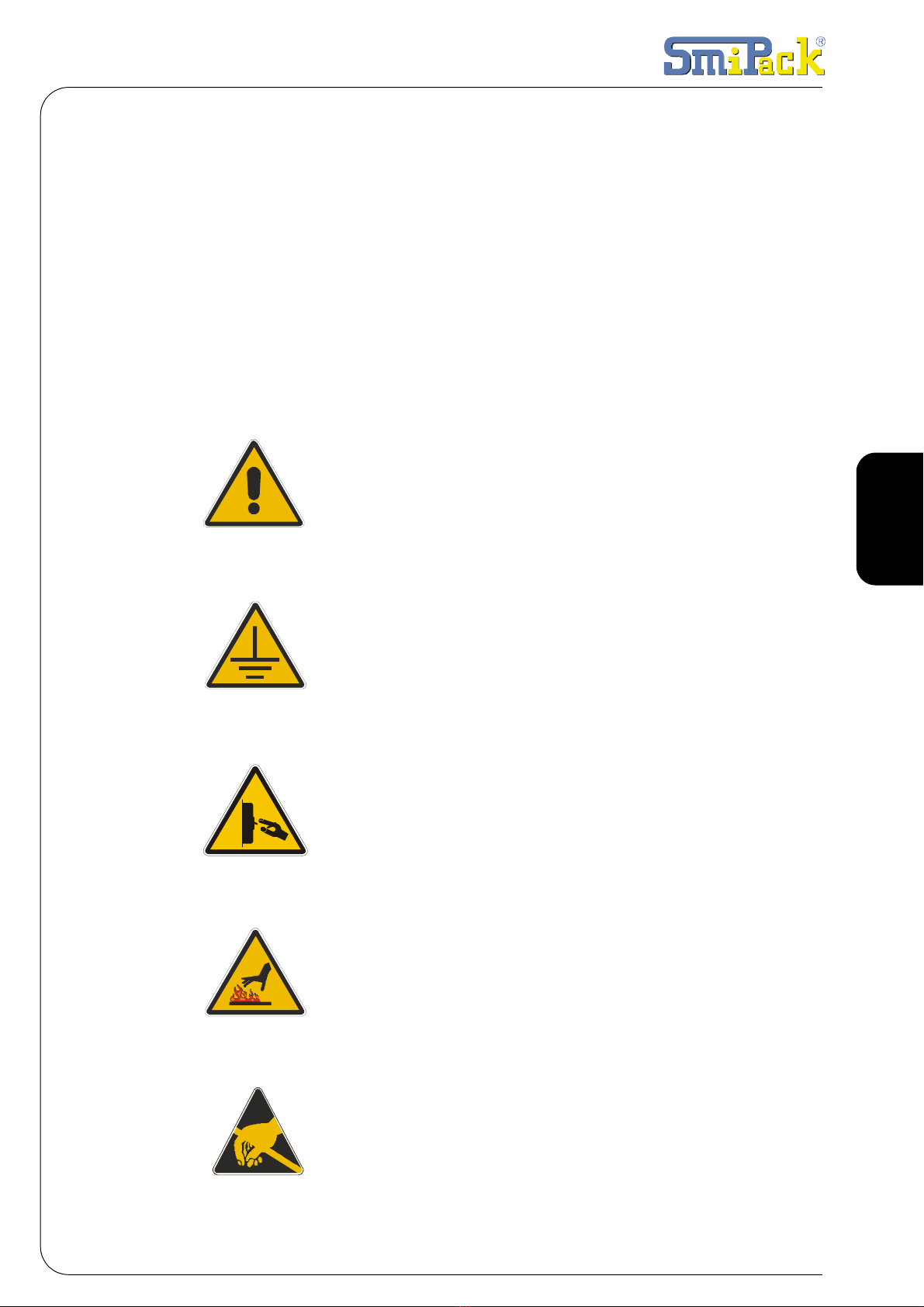
1.5 LEGEND
All instructions and notes contained in this manual are graphically represented in the
following way:
ATTENTION: READ CAREFULLY BEFORE
OPERATING.
DANGER OF ELECTROCUTION: EARTHING
IS COMPULSORY.
DANGER OF ELECTROCUTION: REMOVE
VOLTAGE BEFORE PERFORMING THE
INDICATED OPERATIONS.
DANGER OF BURNING DUE TO HIGH
TEMPERATURE SURFACES.
WARNING! DON’T TOUCH.V

68 / 282
1. Regulations and general instructions
DANGER OF TRAPPING BETWEEN
MECHANICAL MEMBERS.
DANGER OF SHEARING.
DO NOT CARRY OUT MAINTENANCE WITH
MEMBERS IN MOVEMENT.
WARNING! BEFORE OPERATING, CHECK
THAT THE MACHINE TYPE IS THE ONE THAT
HAS BEEN BOUGHT.

69/282
ENGLISH
Use and maintenance manual ßP700
2.1 DESCRIPTION OF THE MACHINE
2.2 WEIGHT AND DIMENSIONS OF THE PACKED MACHINE
Fig. 2.1.1 GLOSSARY
1Feeding bar
2Sealing blade
3Reel holder
4Tensioning bars
5Electronic card
6Connecting belt
Fig. 2.2.1
ßP700
X1750 mm
Z2120 mm
Y1200 mm
WEIGHT 377 Kg
2. MACHINE INSTALLATION
1
2
3
4
5
6
Z
YX

70/282
2. Machine installation
2.3 WEIGHT AND DIMENSIONS OF THE MACHINE
2.4 TRANSPORT AND UNPACKING
ATTENTION!
Before handling make sure that the hoisting equipment are suitable to lift the
load that has to be handled.
In the case of long storing, place the machine in a sheltered environment with a
temperature between -15°C and +55°C degree of humidity, variable between 30% and
90% without condensation.
Fig. 2.3.1
ßP700
X1605 mm
Zmin. 1940 mm
max. 2000 mm
Y930 mm
WEIGHT 304 Kg
SMIPACK S.p.A. in function of the
means of transport and of the type of
products to be shipped utilizes pac It is
recommended to handle with great
care the machine during transport and
positioning.
The forwarder is responsible for every
damage that may occur during
transport.
Unpack the unit making sure not to
damage any exposed parts.
The distance to observe Aand B, to lift
the machine are:
Fig. 2.4.1 MODEL A B
ßP700 430
mm
900
mm
Y
Z
X
AB
71/282
ENGLISH
Use and maintenance manual ßP700
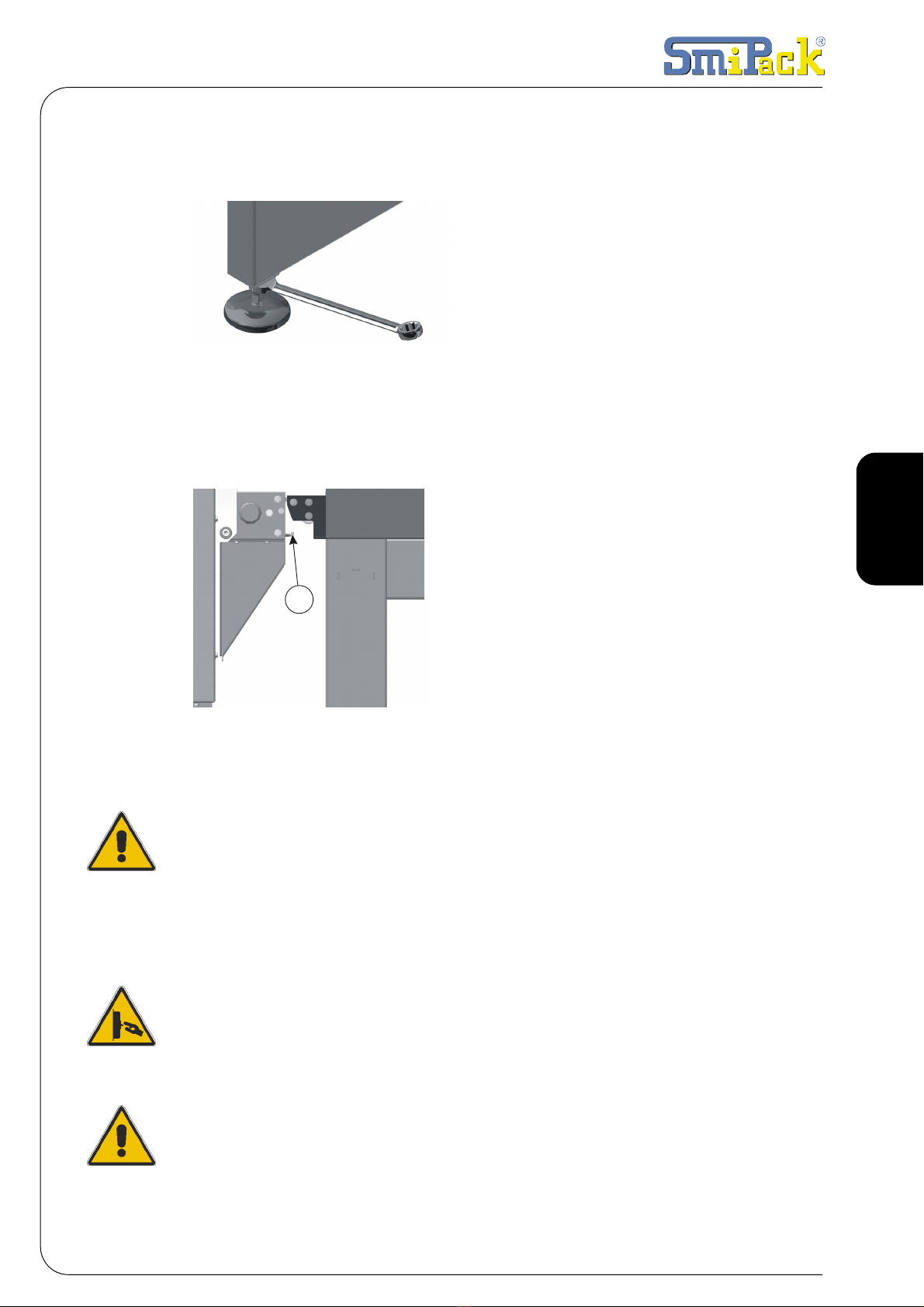
2.5 POSITIONING AND LEVELLING
2.6 ADJUSTING THE CONNECTION BELT AND FASTENING
2.7 DEMOLITION AND DISPOSAL
ATTENTION!
The machine does not contain dangerous components or substances that
require particular removal procedures.
Regarding the elimination of the various materials, it is necessary to follow the
regulations of the Country in which the tunnel will be dismantled.
2.8 ELECTRICAL CONNECTIONS
All operations for the connection to the mains must be carried out with no
voltage applied to the machine.
In the case which someone wants access to the electrical system, remember to
turn off the power supply and wait at least 5 minutes before operating.
Fig. 2.5.1
Make sure that the floor, in the installation area,
does not present irregularities that may
prevent the normal and correct positioning of
the machine. After placing a level on the upper
part of the frame, level the machine using the
adjustable support feet then lock them by
tightening the locknuts.
Fig. 2.6.1
After levelling the belts and the shrink-
wrapping machine, position the machine's
connection belt as close as possible to that of
the tunnel.
The tunnel's belt must be 1 mm higher than the
shrink wrapping machine's belt to avoid the
pack from falling at the tunnel inlet. Adjust this
distance by working on the screws 1
1

72/282
2. Machine installation
EARTHENING IS COMPULSORY!
The machine's connection to the mains must be carried out in thorough compliance
with the regulations of the user's country.
Make sure that the frequency and voltage of the machine's power supply (as indicated
on the nameplate to be found on the rear of the machine) correspond to the mains'.
2.9 TECHNICAL DATA FOR THE ELECTRIC CONNECTION
2.10CONDITIONS OF USE
Make sure that there is enough space for easy application and maintenance.
THE MACHINE NEEDS AN INSTALLATION IN A CLOSED AND WELL AIRED
SURROUNDING, WHERE THERE ARE NOT ANY EXPLOSION OR FIRE
DANGEROUS. THE MINIMUM LIGHTING MUST BE 300 LUX
Make sure that there is enough space for easy application and maintenance.
Position the machine in the planned space with no humidity, flammable materials, gas,
and explosives and making sure that it is level on the floor. The rated temperatures can
vary from +10°C to +40°C, with relative humidity from 30% to 80% without
condensation
SOUND EMISSION PARAMETERS THAT HAVE BEEN DECLARED DISSOCIATED,
IN CONFORMITY WITH THE ISO 4871 REGULATION: LPFA = 73,1 dB
ASSOCIATED UNCERTAINTY KpA = 4dB
Degree of protection of the electric equipment = IP33
ATTENTION!
The pressure and the plate acoustical power of the machine can change
depending on the material of containers to be packaged. Therefore, the user
must perform an assessment on the noise exposure of his personnel in
accordance with the types of packages worked, so as to equip his operators with
suitable personal protection equipment.
BP700
RATED VOLTAGE 380-415 V ~
RATED FREQUENCY 50-60 HZ
RATED POWER 1450 W
RATED CURRENT 4 A
+40°C
+10°
C

73/282
ENGLISH
Use and maintenance manual ßP700
3.1 OPERATING FEATURES OF THE MACHINE
The semi-automatic shrink-wrapping machine ßP700 has a productive capacity of 5
to 10 packs per minute.
3.2 MACHINE IDENTIFICATION
3.3 MAXI. PRODUCT DIMENSIONS
3.4 SHRINK-WRAPPING FILM CHARACTERISTICS
Fig. 3.2.1
On the rear of every machine is
applied a nameplate showing the
EC marking, the main technical
data such as model, serial n.,
power, etc., to be notified to the
builder in case of problems.
Fig. 3.3.1
ßP700
X350 mm
Z350 mm
Y520 mm
Fig. 3.4.1
The machine has been designed to
obtain the packaging of the most
diversified products, using a shrink-
wrapping film thickness of 40 and 100
µm.
3. INFORMATION ON THE MACHINE
Y
Z
X
ØMax 300mm
L.Max650mm
74/282
3. Information on the machine
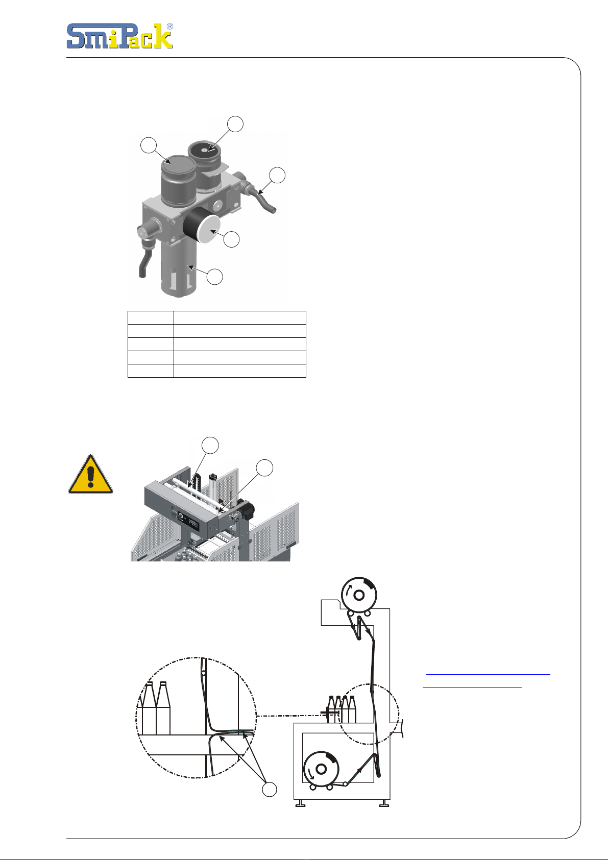
3.5 DATA FOR THE PNEUMATIC INSTALLATION
3.6 FIRST FILM SEALING
Fig. 3.5.1
The air regulation pneumatic module
composed of a padlock valve and a regulator
filter, with relative pressure gauge used to
regulate the air pressure in the circuit.
Pressing the push button placed above the
regulator 2, rotate the handle grip so that air
flows inside the plant. Check the air pressure
on the pressure gauge 4.
For the connection, insert the air source into
the entrance link at Ø8 mm.
Compressed aira:
• Working pressure: 5 Bar
• Max. consumption: 16 Normal litres/cycle
• Max. degree of impurity:
solid particles: 40 µm.
liquid particles: 0.5 PPM
Fig. 3.6.1
The insertion or replacement of the reels must
be performed with the machine switched off.
Center the reels on the relative rollers 1paying
attention to sharp or pointed surfaces. At this
point move the clamps 2leaving a few
millimeters between the same and the reel.
Make the film go through
the tensioning bars as in
fig. 3.7.2.
Position and overlap the
two edges of the film 3
over the sealing bar.
Close the safety door and
switch on the machine
and start the first sealing,
(See par "MANUAL
SELECTION" pag. 76. ) and
then remove wastage.
2
3
4
5
1
1Padlock valve
2Regulator
3Ø8 Power supply
4Pressure gauge
5Filter
3
1
2
Fig. 3.6.2

75/282
ENGLISH
Use and maintenance manual ßP700
4.1 MACHINE START-UP
ATTENTION!
Before operating make sure that the temperature of the sealing bar is the one
that has been set.
4.2 CHOOSING THE OPERATING MODE
Turn the control panel's general switch to pos. ON. Then press the [POWER] key to
start the machine. The temperature of the sealing bar and the number of the
programme that is being used (es.M1) will appear on the viewer.
Fig. 4.1.1
The packaging machine can operate in two ways: manual and automatic.
To choose the operating mode press [F3] and the following video page will appear on
the display:
Fig. 4.2.1
4. PREPARATION TO THE USE OF THE MACHINE
MODE
>AUTO< Manual

76/282
4. Preparation to the use of the machine
4.3 MANUAL SELECTION
Press [F3] and the following mode selection video page will appear on the
display.Press the push button [-] to position yourself on the selection >MANU< and
press [POWER] to confirm and then [ENTER] to go back to the main video page.
At this point the following push buttons are active:
[F1] - by pressing this push button you operate the sealing bar and the press with the
set time and sealing parameters.
[F2] - by pressing this push button you activate the feeding bar adjusted by the set pa-
rameters.
[×]- by pressing this push button you activate the connection belt at a set time.
4.4 AUTOMATIC SELECTION
Press [F3] and the following mode selection video page will appear on the display.
Press the push button [+] to position yourself on the selection >AUTO< and press
[POWER] to confirm and then [ENTER] to go back to the main video page.
The working cycle "AUTO" allows the product to be packed using the two [START]
push buttons placed on the working surface, pressing them simultaneously.
If the two push buttons are released during the feeding progress this last goes back to
the loading position.
The machine operates with the parameters set in the menu [F3].
4.5 EMERGENCY PUSH-BUTTON
When the machine is stopped with the emergency button, all operations are suspended
and the cylinders go back to their starting position. To restore press the push-button
[POWER].
4.6 QUICK SELECTION OF THE PROGRAMS
The microprocessor allows us to store up to 6 different programs, automatic cycle
according to the size of the pack. The number of the program appears at the end of the
second line of the display.
Press the push button [ENTER] and then the keys [+] or [-] to modify the memory ( the
power is disabled automatically).
At this point confirm the position of the memory with [ENTER] and enable the power
again by pressing the push button [POWER].

77/282
ENGLISH
Use and maintenance manual ßP700
4.7 STORING PROGRAMS AND MODIFICATIONS
Pressing the key [F3] you access to the machine's adjustment parameters.
To change the video page in the menu use the keys [×]e [Ø]:
1 • Mode
Menu that displays the working cycle. See previous paragraphas.
Fig. 4.7.1
2 • Pack exit
Menu to adjust the belt's pace. (value 0-50)
Fig. 4.7.2
Using the keys [+] and [-] you increase or decrease the value of a unit.
This operation allows accumulation of more packs on the belt at a set time interval.
3 • Feeding bar pause
The feeding bar stops for the set time so that unstable packs can be placed in the
correct position. (value 0-15)
Fig. 4.7.3
Using the keys [+] and [-] you increase or decrease the value of a unit.
MODE
>AUTO< Manual
Exit parcel 1
M1
Pusher pause 10
M1

78/282
4. Preparation to the use of the machine
4 • Sealing timer
Menu that sets the sealing time of the sealing bar (value 0-10)
Fig. 4.7.4
Using the keys [+] and [-] you increase or decrease the value of a unit.
5 • Bar temperature
Menu that sets the sealing temperature. (value 50-160°C increase 1°C)
Fig. 4.7.5
Using the keys [+] and [-] you increase or decrease the value of a unit.
6 • Pieces
Menu that displays the number of pieces. (value 0-65000 increase +1)
Fig. 4.7.6
Press the push button [+] to set to zero.
7 • Storage
Allows you to store the parameters set in the different memories. (value 0-5)
Fig. 4.7.7
Press [ENTER] to store the parameters in a memory.
Press [+] or [-] to change memory.
Seal time 1
M1
Bar °C 100
M1
Pieces 200
+=Put a zero
Enter=Store
Memory 1
Table of contents
Other Smipack Industrial Equipment manuals


Popular Industrial Equipment manuals by other brands

INTORQ
INTORQ 14.800 Series operating instructions

Wenger
Wenger StageTek Guardrail Assembly & operating instructions

Rockwell Automation
Rockwell Automation Allen-Bradley 140G Series installation manual

OMGA
OMGA OPTIMA 120 Operation and maintenance manual

BOCI
BOCI BLT441 product manual

Gigasense
Gigasense II user manual

HYVA
HYVA R Series user manual

WOOD'S POWR-GRIP
WOOD'S POWR-GRIP MRTALPCH611LDC3 instructions

ABB
ABB HT608689 Operation manual

ADF Web
ADF Web M-Bus manual

Nidec
Nidec LEROY-SOMER LSA 49.1 IC 06 Installation and Maintenance

Unitary products group
Unitary products group P XU-V/G9V-UP Series installation manual


