BOCK EX-HG12P User manual
BOCK EX-HG
12
P
Assembly instructions
09691-01.2021-Gb
Translation of the original instructions
colour the world
of tomorrow
BOCK®
Device category 2 G
acc. to directive 2014/34/EU
EX-HG12P75-4 EX-HGX12P/75-4 EX-HG12P/75-4HC
EX-HG12P/90-4 EX-HGX12P/90-4 EX-HG12P/90-4HC
EX-HG12P/110-4 EX-HGX12P/110-4 EX-HG12P/110-4HC
EX-HG12P/60-4S EX-HGX12P/60-4S EX-HG12P/60-4SHC
EX-HG12P/75-4S EX-HGX12P/75-4S EX-HG12P/75-4SHC
EX-HG12P/90-4S EX-HGX12P/90-4S EX-HG12P/90-4SHC
EX-HG12P/110-4S EX-HGX12P/110-4S EX-HG12P/110-4SHC

2
D
GB
F
E
I
09691-01.2021-DGbFEIRu
About these instructions
Read these instructions before assembly and before using the compressor. This will avoid misunder-
standings and prevent damage. Improper assembly and use of the compressor can result in serious
or fatal injury.
Observe the safety instructions contained in these instructions.
These instructions must be passed onto the end customer along with the unit in which the
compressor is installed.
Bock GmbH
72636 Frickenhausen
Manufacturer
Contact
Bock GmbH
Benzstraße 7
72636 Frickenhausen
Germany
Phone +49 7022 9454-0
Fax +49 7022 9454-137
www.bock.de
1 Safety 4
1.1 Identicationofsafetyinstructions
1.2 Qualicationsrequiredofpersonnel
1.3 Safety instructions
1.4 Intended use
2 Product description 7
2.1 Short description
2.2 Ignition protection concept
2.3 Name plate
2.4 Type key
2.5 ATEX-identication
Contents Page

D
GB
F
E
I
3
09691-01.2021-DGbFEIRu
Contents Page
3 Areas of application 12
3.1 Approved refrigerant
3.2 Important information on the use of hydrocarbons
3.3 Oil charge
3.4 Limits of application
4Compressor assembly 15
4.1 Ignition source control of the compressor
4.2 Storage and transport
4.3 Setting up
4.4 Pipe connections
4.5 Pipes
4.6 Laying suction and pressure lines
4.7 Operating the shut-off valves
4.7 Operating mode of the lockable service connections
4.9 Suctionpipelter
5 Electrical connection 19
5.1 Potentialequalization
5.2 Information for contactor and motor contactor selection
5.3 Terminal cross section for leads
5.4 Connection of the drive motor
5.5 Circuit diagram direct start
5.6 Electronic trigger unit INT69 EX2
5.7 Connection of the electronic trigger unit INT69 EX2
5.8 Functional test of the electronic trigger unit INT69 EX2
5.9 To verify the intrinsic safety of the PTC hot gas sensor
6 Commissioning 27
6.1 Preparations for start-up
6.2 Pressure strength test
6.3 Leak test
6.4 Evacuation
6.5 Refrigerant charge
6.6 Start-up
6.7 Avoidingliquidsluggings
6.8 Preventing icing on the compressor
7 Maintenance 29
7.1 Preparation
7.2 Work to be carried out
7.3 Spare part recommendation/accessories
7.4 Screw connections
7.5 Decommissioning
8 Accessories 31
8.1 Oil sump heater
9 Technical data 32
10 Dimensions and connections 33
ECTypeExaminationCerticate 36
IECExCerticateofConformity 39
Service 43
4
D
GB
F
E
I
09691-01.2021-DGbFEIRu
1|Safety
1.2 Qualicationsrequiredofpersonnel
DANGER Indicates a dangerous situation which, if not avoided,
will cause immediate fatal or serious injury.
WARNING Indicates a dangerous situation which, if not avoided,
may cause fatal or serious injury.
CAUTION Indicates a dangerous situation which, if not avoided,
may cause fairly severe or minor injury.
ATTENTION Indicates a situation which, if not avoided,
may cause property damage.
INFO Important information or tips on simplifying work.
WARNING Inadequatelyqualied personnelposestheriskofaccidents,the
consequencebeingseriousorfatalinjury.Work on compressors
must therefore only be performed by personnel with hereinafter
qualicationsandappropriatetoadditionalqualicationaccording
to EN 60079-14.
• For example, a refrigeration technician, refrigeration mechatronic
engineer. As well as professions with comparable training, which ena-
bles personnel to assemble, install, maintain and repair refrigeration
and air-conditioning systems. Personnel must be capable of assessing
the work to be carried out and recognising any potential dangers.
1.1 Identicationofsafetyinstructions:

D
GB
F
E
I
5
09691-01.2021-DGbFEIRu
1.3 Safety instructions
1|Safety
The Bock refrigerating compressor named in the title is intended for installation in machines that were
set up in areas falling under the EU Explosion Protection Directive 1999/92/EC (operator directive). In
the European Union, electrical as well as mechanical devices operated in explosive atmospheres must
fulfil what are known as ATEX (ATmospheres EXplosibles) conditions.
The compressors are specially designed for the category shown on the name plate in accordance with
the ATEX directive and may only be used in conformity with the conditions specified and documented
in the set-up area (explosion protection document). User safety is taken into account as a particular
focus of design. But it is permissible to start up the compressor only if it was installed in accordance
with these instructions and the entire system into which it is integrated has been inspected in accor-
dance with legal regulations and approved.
The declarations and remarks by Bock can only refer to the product itself. We assume that the appli-
cable regulations, standards and technical rules are followed in installation and during operation. The
plant constructor/operator must evaluate the interactions with other devices and components of the
system and with the environment, especially regarding potential ignition sources.
WARNING • Refrigerating compressors are pressurised machines and there-
forerequireparticularcautionandcareinhandling.
• Risk of burns! Depending on the operating conditions, surface
temperatures of over 60 °C on the pressure side or below 0 °C on
the suction side can be reached.
• The maximum permissible overpressure must not be exceeded,
even for testing purposes.
• The compressor may be operated only if it is free of defects!
• No work may be performed when an explosive atmosphere is
present!
• Smoking,reandopenamearestrictlyprohibited!Mobiletele-
phones must be switched off!
• Strongly charge-generating processes must be excluded within
2 meters. The contact of rapidly moving particles with the sur-
face of the compressor must be avoided with certainty (e.g.
pneumaticallymoveddust,owinguids,directventilation,belt
drives, brushes, foils, etc.).
• Perform installation work only if no damage, leaks and/or
appearances of corrosion can be recognized.

6
D
GB
F
E
I
09691-01.2021-DGbFEIRu
1|Safety
These assembly instructions describe the standard version of the EX-HG12(P)(e) manufactured by
Bock. The compressor is intended for use in refrigeration systems inside explosion-endangered areas
underthedesignationspeciedonthenameplateinaccordancewiththeEuropeanATEX Directives.
Useofthespeciedrefrigerantsaswellasobservanceoftheoperatinglimitsandlistedstandards
must be ensured in any case. Likewise, all accessories available from, approved and specially marked
by Bock are exclusively approved, according to their intended use, for attachment to and operation
with Bock compressors of appliance category 2 in accordance with Directive 2014/34/EU.
1.4 Intended use
WARNING Any other use of the compressor and its approved accessories is
prohibited! The ATEX permit is voided if the compressor is used
outside the operating limits or undergoes inadmissible design
changes!
D
GB
F
E
I
7
09691-01.2021-DGbFEIRu
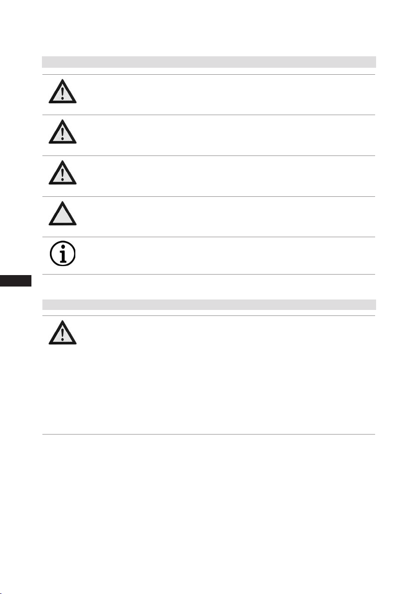
Dimension and connection values can be found in Chapter 10.
Name plate
Fig. 1
Fig. 2
Oil sight glass
Valve plate
Discharge
shut-off valve
Oil pump
Terminal box
Potentialequalization
Suction
shut-off valve
Drive section
Motor section
Transport eyelet
Cylinder cover
2|Product description
• Semi-hemetic two-cylinder reciprocating compressor with oil pump lubrication
• Suction-gas-cooled drive motor
• For use in explosion-endangered areas
2.1 Short description

8
D
GB
F
E
I
09691-01.2021-DGbFEIRu
2|Product description
2.2 Ignition protection concept
In accordance with Directive 2014/34/EU, Bock ATEX compressors are suitable for use in device
category 2 for explosive gas atmospheres up to temperature class T3 and explosion hazard subgroup
IIB/IIC.
The entire compressor, including motor, is perceived as technically tight and therefore does not need
an ignition protection.
To prevent ignition risk caused by working materials also during system malfunctions, all used work-
ingmaterialshavetomeettherequirementsforthetemperatureclassofthecompressor.Thesurface
temperature of the compressor may not exceed 80 % of the ignition temperature of the working
material. For this reason all working materials need to have an auto-ignition temperature of > 250 °C.
To protect against high temperatures that may occur during incorrect operation or faults at the com-
pressor, the areas with the highest heat potential are controlled with temperature sensors (Ex h).
The installation of the electronic control unit INT69 EX2 and the safety barrier,
both included in the scope of supply, is therefore absolutely necessary.
Theconnectionareasforloadcircuitsaredesignedaccordingtotherequirementsoftheappliance
category in Ex e. The circuits for the temperature sensors of the used ignition source control Ex h have
to be intrinsically safe to prevent inadmissibly high thermal or electric values. To ensure the intrinsic
safety, the included safety barrier has to additionally be integrated in the electric circuit according to
this assembly instruction. The terminal board is designed for the protection type Ex de. The whole
electricconnectionareaisprotectedbyahousingthatcomplieswiththerequirementsfortheprotec-
tion type increased safety (Ex e).
Thescopeofdeliveryofthestandardcompressorcomprisesaconductivepaintnish,thatissuitable
for the use in explosion group IIC. If the compressor is delivered with the accessory "Offshore Paint
Finish", the application is restricted to explosion group IIB.

D
GB
F
E
I
9
09691-01.2021-DGbFEIRu
Accessories
Heating elements for the compressors to protect against explosion risks are designed in the protection
types increased safety (Ex d) and have to have to be mounted stationary at the designated areas in
the compressor housing. The heating elements can be operated without temperature- and oil level
controlsincethethermaltypetestingbythemanufacturerveriedthattheheatingelementsprevent
the exceeding of the temperature class of the compressor. The control has to be carried out in a way
that the heating element can only be operated during shutdown of the compressor.
2|Product description
Equipment Type of ignition protection EPL1)
Terminal box Ex e b
Terminal board Ex d b
Through terminals in the terminal box Ex e b
Cable entrances /
plug
Ex e /
Ex d
b
b
Line entrances Ex d b
Oil sump heater Ex d b
Hot gas PTC sensor Ex i a
1)EquipmentProtectionLevel
10
D
GB
F
E
I
09691-01.2021-DGbFEIRu
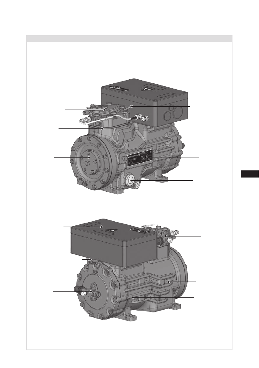
EX-HG12P/110-4 S
IP66
AY15595A008
6,1 A
26 A 11,3
9,4
II 2G Ex d e ia IIC T3 Gb / EPS 16 ATEX 1095 X
1
2
3
4
5
6
7
8
9
10
12
13
11
14
2|Product description
2.2 Name plate (example)
2.3 Name plate (example)
50Hz
60Hz
}
}
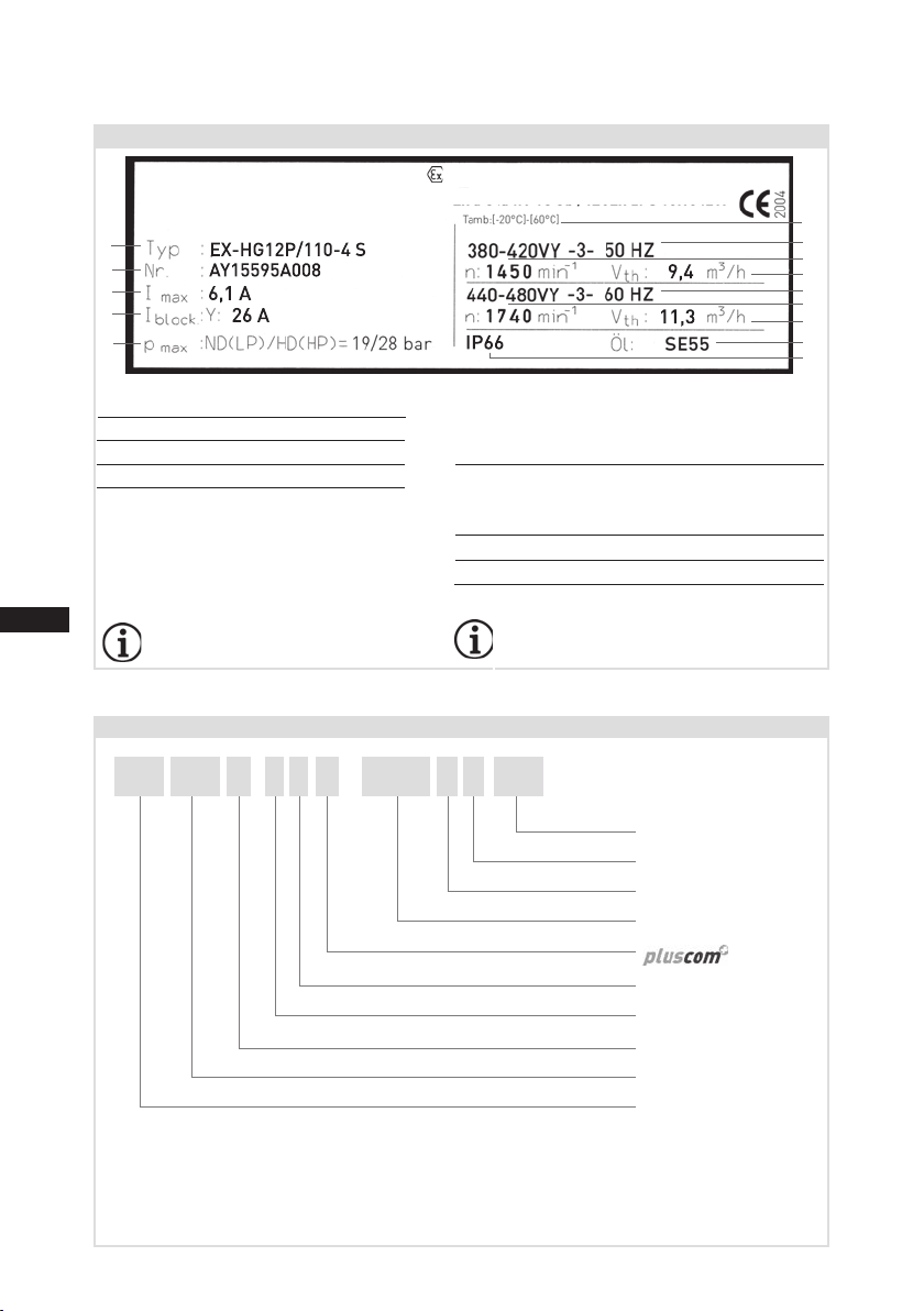
2.4 Type key (example)
¹) HG - Hermetic gas-cooled (suction gas-cooled)
²) X - Ester oil filling (HFC refrigerant ), e.g. R134a, R404A, R507, R407C)
³) Additional declaration for Pluscom compressors
4) S - More powerful motor, e.g. air-conditioning applications
1 Type designation 6 Voltage,circuit,frequency
2 Machine number 7 Nominal rotation speed
3 maximum operating current 8 Displacement
4 Starting current (rotor blocked) 9 Voltage,circuit,frequency
5 ND (LP):
max. admissible operating
10 Nominal rotation speed
pressur
e (g) Low pressure side 11 Displacement
HD (HP):
max. admissible operating
12 Oiltypelledatthefactory
pressur
e(g) High pressure side 13 Terminal box protection type
14 Permissible ambient temperature
Electrical accessories can change
the IP protection class!
Observe the limits of
application diagrams!
/
HG
EX 21 P 110-
-4 SX
for hydrocarbons
Motor variant 4)
Number of poles
Swept volume
³)
Number of cylinders
Size
Esteroillling²)
Series ¹)
Ex-design
HC
Fig. 3
Bock GmbH, Benzstr. 7
72636 Frickenhausen, Germany
BOCK II 2G Ex db eb ia IIC T3 Gb / EPS 16 ATEX 1 095 X
Ex db eb ia IIC T3 Gb / IECEx EPS 16.0042X

D
GB
F
E
I
11
09691-01.2021-DGbFEIRu
EPS 16 ATEX 1095 X / IECEx EPS 16.0042 X
Bureau Veritas (inspection authority)
Consumer Products Services
Germany GmbH
International explosion protection
Year of test/Test report number
Year of test
Bureau Veritas (inspection authority)
Consumer Products Services
Germany GmbH
ATEX-CerticateofConformityIECEx-CerticateofConformity
Special conditions:
see"ConditionsofCertication"
Special conditions:
see point 17 of the EC type
examinationcerticate
Test report number
ATmospheres EXplosibles
european explosion protection
2|Product description
2.5 ATEXidentication/IECExidentication
Explosion group II for Ex-endangered
areas (not underground buildings)
Suitability for gas-explosive area
Device category 2 (= zone 1)
Temperature class T3 (max.200 °C)
Equipmentprotectionlevel
Explosion subgroups,
IIB=Offshorepaintnish
IIC=ESDpaintnish
Intrinsicallysafeequipment
Flameproof enclosure, heater (option)
Europ. explosion protection acc. to
Direc. 2014/34/EU
Increased safety
2G T3 GbII ia IIB/IIC
Ex
db eb

12
D
GB
F
E
I
09691-01.2021-DGbFEIRu
3|Areas of application
3.1 Approved refrigerant
• HFKW / HFC: R134a, R404A, R507, R407C
• (H)FCKW / (H)CFC: R22
• Hydrocarbons: R290, R1270
3.2 Important information on the use of hydrocarbons
Hydrocarbons (combustible refrigerants) may be used in the compressors named in the title only if all
relevant and applicable regulations, standards and technical rules are followed. National safety regu-
lations must be observed. In addition, we refer to the following applicable standards and regulations:
EN 378, BGR500, TRBS 2152, EC Directives 1999/92/EC and 2014/34/EU.
The compressor and the refrigeration system must be permanently equipped with clear, identical
labels/plates (ISO3864) that state that combustible refrigerants are used. This warning plate must be
unremovably attached to the compressor.
A hazard analysis in accordance with the Operational Safety Ordinance must be performed for the
set-up location. Use and handling of the refrigeration system and compressor are to be governed in
the explosion protection document.
Installation, placement into operation, service and repair (as permitted by the manufacturer) may only
be performed by personnel who have been specially trained on combustible refrigerants.
If the compressor has to be removed from the system for inspection/maintenance/repair, the remaining
refrigerantmustbesuctionedoutandthecompressorevacuated,lledwithnitrogen(<0.5bar)and
closedgas-tight.Thecompressormustbeequippedwithatagthatclearlystatesthatthecompressor
was operated with combustible refrigerant (name the refrigerant).
If the system contains combustible refrigerants or residues, extreme caution must be exercised when
workingonthecompressorduetothedangerofexplosion.Thisappliesespeciallyfortheuseofre,open
ameorotherignitionsources(e.g.electronicdevices,mobiletelephones,staticcharges,sparks,...).
During maintenance and repair, it must be noted that hydrocarbon residues may remain dissolved in
theoil.Inadditionuseddryerscontainbottomsoftheinammablerefrigerants.Flushthedryerwith
nitrogen and supply it to the recycling.
It should be noted that the solubility of hydrocarbons in oil can be very high, especially at high suction
pressures.Ahigh-viscositylubricantmayberequired,dependingontheapplicationandexperience.
The lubricant must be released for use by Bock. Depending on the application, a pump-down switch
should also be added (e.g. when the refrigeration system is set up outside).
INFO Used refrigerants have to have a self-ignition temperature of
> 250 °C.
D
GB
F
E
I
13
09691-01.2021-DGbFEIRu
3|Areas of application
The following refrigerants are approved for the compressor:
3.3 Oil charge
Refrigerant Oil grade
R22 FUCHS Reniso SP 46
R134a, R404A, R507, R407C FUCHS Reniso Triton SE 55
R290, R1270 BOCKlub G68
Compressorswithesteroillling(FUCHSRenisoTritonSE55)aremarkedwithanX in the type
designation (e.g. EX-HGX12P/110-4).CompressorswithoilllingBOCKlub G68 are marked with
HC (eg. EX-HG12P/110-4 HC).
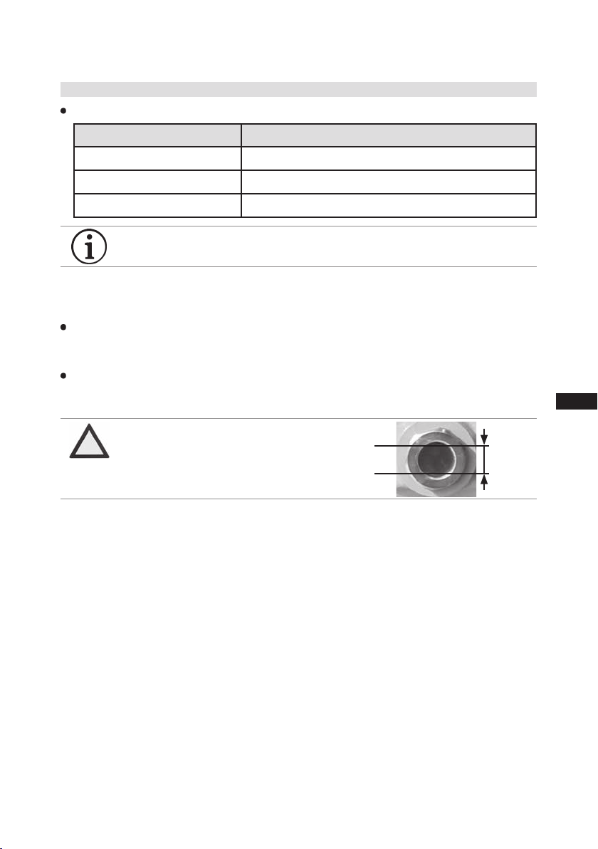
Oil level: The oil level from the factory reaches the upper edge of the sight glass. The oil level must
be regulated in operation; if necessary to achieve a correct oil level (see Fig. 4), oil may have to be
drained off or added.
Operate compressors only with the approved refrigerants and the corresponding assigned and
approved oils. Other combinations (e.g. R22 with ester oils) are not permitted!
Conversion to another refrigerant/oil is not permitted!
ATTENTION The oil level must be in
the visible part of the sight
glass; damage to the com-
pressor is possible if over-
filled or underfilled! Fig. 4
max.
min.
0,5 Ltr.
oil level ~
~
INFO Used refrigerant oils have to have a self-ignition temperature of
> 250 °C.

14
D
GB
F
E
I
09691-01.2021-DGbFEIRu
3|Areas of application
3.4 Limits of application
ATTENTION Compressor operation is possible within the operating limits.
These can be found in Bock compressor selection tool (VAP)
under vap.bock.de. Observe the information given there.
- Max. permissible discharge end temperature 140 °C.
-Max.permissibleswitchingfrequency8x/h.
- A minimum running time of 3 min. steady-state condition
(continuous operation) must be achieved.
Suction gas overheating ∆toh:
The correct setting of the suction gas overheating temperature
∆tohatthecompressorentranceisofdecisiveimportance:
Too low ∆toh =>dangerofliquidoperation
Too high ∆toh => danger of compressor overheating
∆toh min=7-10K,individualadjustmentrequired.
Permissibleambienttemperaturerange−20°Cto+60°C.
Avoid continuous operation near the limits.
Foroperationwithfrequencyconverter:
- the maximum current and power consumption may not
be exceeded.Duringoperationabovethe mainsfrequency
the application limit can be restricted.
Variablefrequencyrange:30-70Hz
During operation in the vacuum range, there is a danger of air
entering on the suction side. This can cause chemical reactions,
pressure rise in the condenser and an excessive pressure gas tem-
perature as well as shifting of the refrigerant ignition limit into the
critical range. Avoid absolutely operation in the vacuum range!

D
GB
F
E
I
15
09691-01.2021-DGbFEIRu
4|Compressor assembly
4.1 Ignition source control of the compressor
INFO • Newcompressorsarefactory-lledwithinertgas.Leavethisservice
charge in the compressor for as long as possible and prevent the
ingress of air.
•Check the compressor for transport damage before starting any
work.
•Before starting work, obtain written work release.
•Observe national regulations when setting up explosion-protected
systems(withintheEU:ATEXDirective1999/92/EG,EN60079-14,
EN 60079-17 a.o.).
• Use only tools permitted for explosion-protected systems (within
the EU, in accordance with EN 1127-1).
• Observe work safety rules (TRGS 727, e.g. protective shoes,
clothing etc.)!
To protect against an exceeding of temperature the protection type ignition source control "h" is
used at the compressor. Via sensors, the areas with the highest heat potential at every cylinder
cover are controlled. Additionally, the temperature of the motor winding is controlled by the safety
device INT69 EX2.
The permissible limit temperatures for normal operation of the compressor were set with 130 °C for
the motor and with 140 °C for the hot gas side of the cylinder cover. If one of those values is exceeded,
the compressor is shut down by the control device INT69 EX2. Besides the installation according to
wiring diagram, the operator/installer does not have to regard other parameters for the correct func-
tioning of the ignition protection system. A function check however has to be carried out before every
startup of the compressor according to section 5.7 of this assembly instruction.
For a safe function of the ignition source control the INT69 EX2 has to be installed according to the
wiringdiagramg.25,therestartinterlock(bridgeB2)mustnotberemovedinanycase.Checkthe
function of the ignition protection system according to section 5.8. Defective sensors or ignition pro-
tection systems have to be replaced before reconnection of the compressor.
Operation of the compressor without igintion source control is not permitted!
After shutdown by the INT69 EX2, precise error diagnostics and error correction is necessary.
The INT69 EX2 has a restart interlock that can only be interrupted by means of voltage inter-
ruption.
16
D
GB
F
E
I
09691-01.2021-DGbFEIRu
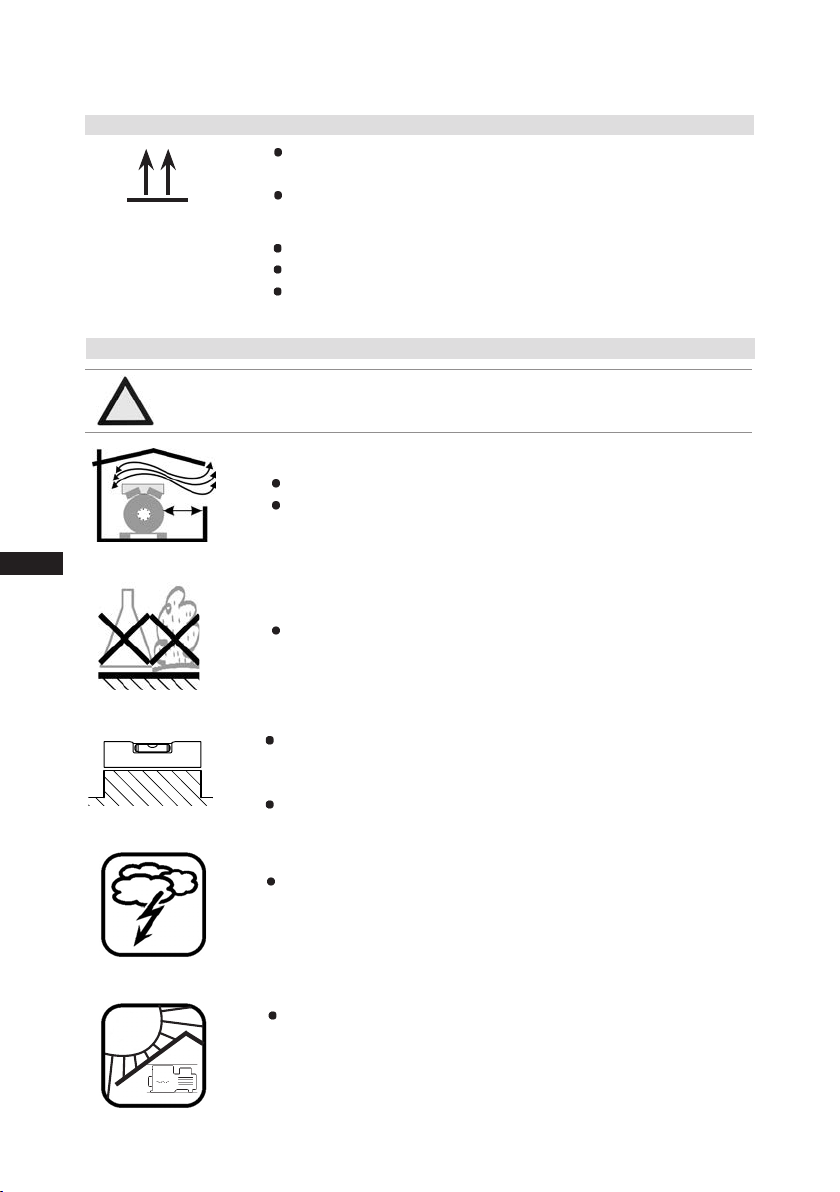
Setuponanevensurfaceorframewithsufcientload-
bearing capacity. Only set up on a slant after consulting
with the manufacturer.
Single compressor preferably on vibration damper.
Provideadequateclearanceformaintenancework.
Ensureadequatecompressorventilation.
Do not operate in an aggressive and/or corrosive atmosphere.
Fig. 7
Fig. 8
Fig. 9
F
E
D
C
B
A
1
2
3
4
F
E
D
C
4
3
2
1
A
B
Tol.-Ang. DIN ISO 2768-mK
Ra Rz
Maß
Passung
Freigabe
Alternativbezug:
Baumustergeprüft
Teil inaktiv
Lieferantenzeichnung
-
-
K.-Auftrag:
PL:
Zeichnung ungültig
Entwicklungsstand
Teil keine Serie
120
400
±0.5
über 0.5
bis 6
Benzstraße 7 - 72636 Frickenhausen - Germany - www.bock.de
-
-
Unbemaßte Radien:
-
Diese Zeichnung ist unser Eigentum!
Sie darf ohne unsere Genehmigung weder nach-
gebildet, vervielfältigt, oder Dritten Personen zu-
gänglich gemacht werden. Der Nachbau nach
dieser Zeichnung, oder an Hand der nach dieser
Zeichnung hergestellten Gegenstände durch den
Abnehmer oder Dritte ist nicht gestattet.
Wir behalten uns alle Rechte, gemäß DIN ISO 16016
an dieser Zeichnung vor.
Bearb.
Datum
Änderungs-Nr.
Werkstoff:
Ausgangsteil, bzw. Rohteil:
--
Gepr.
Name
Datum
19.04.
Werkstückkanten
DIN ISO 13715
Ersatz für:
Ersetzt durch:
Erstellt
2010
Geprüft
-
Kurz
Zone
1/x
Oberflächenbehandlung / Härte:
-
Blatt:
Änderungsbeschreibung
400
Benennung:
±0.8
1000
30
6
-
±0.3
120
30
±0.2
Zeichn.-Nr. Teile-Nr.
Oberflächenangaben ISO 1302
x.xxxx-xxxxx.x
Zust.
Gußtoleranzen:
Gewicht: (kg)
±0.1
Maßstab:
1:1
Wasserwaage
für Indesign
Der Lieferant muß sicherstellen, dass die Ware in
einwandfreiem Zustand angeliefert wird (Korrosions-
schutz, Verpackung für sicheren Transport).
Rz 25
Rz 160
s
25
z
y
x
w
u
t
0,05
Rz 1,6
0,3
0,7
1,6
2
Rz 16
6,3
Rz 63
Rz 6,3
Rz 12,5
F:\user\kurz\3D Sachen\3D Teile\Zeichnungen\Wasserwaage
4|Compressor assembly
Lightening protection: If the compressor is set up outdoors,
a lightening protection concept has to be integrated.
Sun protection: If the compressor is set up outdoors, it has
to be protected from direct sunlight.
Fig. 10
Fig. 11
4.3 Setting up
?
4.2 Storage and transport
Use transport eyelet.
Do not lift manually!
Use lifting gear!
Storageat(−30°C)-(+70°C),maximumpermissiblerelativehumi-
dity 10 % - 95 %, no condensation
Do not store in a corrosive, dusty, vaporous atmosphere or in a com-
bustible environment.
Fig. 6
Fig. 5
ATTENTION Fittings (e.g. pipe holders, additional units, mounting parts etc.)
on the compressor are not permissible!
D
GB
F
E
I
17
09691-01.2021-DGbFEIRu
Fig. 13
4.6 Laying suction and pressure lines
4|Compressor assembly
4.5 Pipes
The pressure and suction shut-off valves have graduated inside
diameters so that pipes in the common millimeter and inch dimensions
can be used. The pipe will be inserted more or less deep, depending on
the dimension.
The connection diameters of the shut-off valves are designed for
maximum compressor performance. Theactualrequiredpipecross
section must be matched to the output. The same applies for
non-return valves.
Fig.12: graduated
internal diameter
4.4 Pipe connections
ATTENTION An explosive atmosphere must not be present!
Do not solder as long as the compressor is under pressure.
Superheating can damage the valve. Remove the pipe supports
therefore from the valve for soldering and accordingly cool the
valve body during and after soldering.
Only solder using inert gas to inhibit oxidation products (scale).
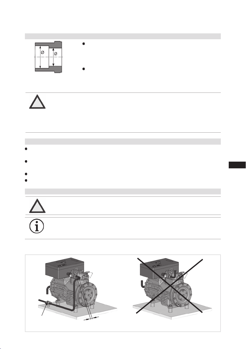
Aruleofthumb:Alwayslaytherstpipesectionstartingfromtheshut-offvalvedownwards and
parallel to the drive shaft.
ATTENTION Improperly installed pipes can cause cracks and tears which can
result in a loss of refrigerant
INFO Proper layout of the suction and pressure lines directly after the com-
pressor is integral to the smooth running and vibration behaviour of
the system.
Pipes and system components must be clean and dry inside and free of scale, swarf and layers of
rust and phosphate. Only use air-tight parts.
Lay pipes correctly. Suitable vibration compensators must be provided to prevent pipes being
cracked and broken by severe vibrations.
Ensure a proper oil return.
Keep pressure losses to an absolute minimum.
As short
as possible Rigid fixed point

18
D
GB
F
E
I
09691-01.2021-DGbFEIRu
Fig. 14 Fig. 15
Valve spindle seal
Release
Tighten
4|Compressor assembly
4.7 Operating the shut-off valves
Before opening or closing the shut-off valve, release the valve spindle seal by approx. 1/4of a turn
counter-clockwise.
After activating the shut-off valve, re-tighten the adjustable valve spindle seal clockwise.
Pipe connection
Pipe connection
4.8 Operating mode of the lockable service connections
Fig. 16
Openingtheshut-offvalve:
Spindle: turn to the left (counter-clockwise) as far as it will go.
—> Shut-off valve completely opened / service connection closed.
Fig. 17
Opening the service connection
Spindle: Turn 1/2- 1 turn to the right clockwise.
—> Service connection opened / shut-off valve opened.
Connection
blocked
Spindle
Spindle Connection
open
Compressor
Compressor
Service connection
closed
Service connection
opened
Afteractivatingthespindle,generallytthespindleprotectioncapagainandtightenwith14-16Nm.
This serves as a second sealing feature during operation.
For systems with long pipes and higher degree of contamination, a lter on the suction-side is
recommended.Thelterhastobebereneweddependingonthedegreeofcontamination(reduced
pressure loss).
4.9Suctionpipelter

D
GB
F
E
I
19
09691-01.2021-DGbFEIRu
5|Electrical connection
DANGER Risk of electric shock! High voltage!
Only carry out work when the electrical system is disconnected
from the power supply!
INFO Connect the compressor motor according to the circuit diagram (s.
g. 19 or sticker inside the terminal box). Comply with local safety
regulations for electrical work, safety standards (within the EU:
EN 60204, EN 60335 among others) and regulations for setting up
electrical systems in explosion-endangered areas (within the EU: IEC/
EN 60079-14 among others).
Avoiddamagetocablettings,sinceotherwiseoperationalsafetycan
beimpaired.Laythecablesothatthettingtotheterminalboxwill
not loosen itself. If necessary (e.g. installation that is not twist free),
protection against loosening can be achieved through check nuts or
appropriate adhesive. Avoid abrasion points on cables.
For cable lead-through at the terminal box, use suitable Ex cable
screw connections in the correct protective version (see name plate).
Use strain relief. Avoid abrasion points on cables.
Install all switching devices outside the explosion-endangered area.
Motor contactors, feed lines and fuses are to be rated according to the
maximum operating current (see name plate). Recommendations for
contactor and motor protection selection are included in the table at
the end of the „Electrical system“ chapter 5.2.
Do not separate contacts 1 + 2 of the motor thermistors under voltage.
Comparethedetailsforvoltageandfrequencyonthenameplatewith
the details for the electricity mains supply. The motor may only be
connected if these details match.
Use a motor protector switch. It should be set to the rated motor current
and checked.
For the installation of phases L1, L2 and L3 to line-up terminals U1, V1
and W1, no solid wire may be used.
Cross section for connection of line-up terminals U1, V1 and W1
= 0,5 - 6,0 mm².
Cross section for connection of line-up terminals 1, 2, 3 and 4 =
max. 2,5 mm².
5 Electrical connection
ATTENTION When attaching accessories with an electrical cable, a minimum
bending radius of 3 x the cable diameter must be maintained for
laying the cable.

20
D
GB
F
E
I
09691-01.2021-DGbFEIRu
Potentialequalizationconnection
Fig. 18
5.2 Information for contactor and motor contactor selection
5|Electrical connection
5.1 Potentialequalization
Beforestart-up,thepotentialequalisationmustbeconnected(seeFig.18).
Allprotectiondevicesandswitchingormonitoringunitsmustbettedinaccordancewiththelocal
safetyregulationsandestablishedspecications(e.g.VDE)aswellaswiththemanufacturer’sinfor-
mation. Motorprotectionswitchesarerequired! Motor contactors, feed lines, fuses and motor
protection switches must be rated on the basis of the maximum working current (see name plate).
For motor protection use a current-dependent and time-delayed overload protection device for moni-
toring all three phases. Set the overload protection device so that it must be actuated within 2 hours,
if there is 1.2 times the max. working current.
INFO Specialattentionmustbepaidtosufcientconductivityofallcontact
points. There must be a large seat (e.g. with ring cable lug).
Theinstalledvoltageequalizationmustbesecuredagainstloosing
andrmlyconnectedtoearth
WARNING Always install all electrical peripheral devices in an external
control cabinet outside the explosion-endangered area!
This manual suits for next models
21
Table of contents
Other BOCK Industrial Equipment manuals


