18 www.bodine-electric.com
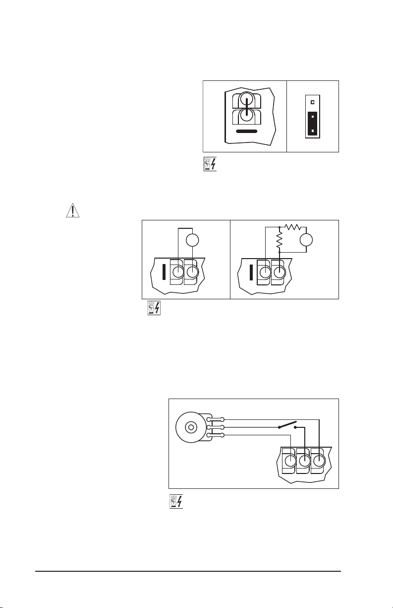
6.5 Boost Mode Selection (J6) –
Jumper J6 is factory set to the
“FIX” position for Fixed Boost.
For Adjustable Boost using the
BOOST Trimpot, set Jumper
J6 to the “ADJ” position. See
Figure 21. Also see Section
13.8 on page 25 for the BOOST
Trimpot range.
6.6 Braking Mode Selection (J7) –
Jumper J7 is factory set to the
“RG” position for Regenerative
Braking when the Start/Stop
Switch is set to the “STOP”
position. For DC Injection
Braking, set Jumper J7 to the
“INJ” position. See Figure 22
on page 19. Also see Section
13.5 on page 24.
When the Injection Brake
Mode is selected, the DECEL
Trimpot is used to adjust the
brake time and intensity.
6.7 Run/Fault Output Relay
Operation Selection (J8) –
Jumper J8 is factory set to
the “R” position for “Run”
operation of the Run/Fault
Relay. For “Fault” operation of
the Run/Fault Relay, set Jumper
J8 to the “F” position. See
Figure 23 on page 19.
For Run/Fault Relay output
contacts, see Section 5.8 on
page 15. The Run/Fault Relay
contact status for various drive
operating conditions is shown
in Table 5 on page 16.
6.8 Stop Contact Selection (J9) –
Jumper J9 is factory set to the
“NO” position for a normally
open stop contact. For remote
normally closed stop contact,
set Jumper J9 to the “NC”
position. See Figure 24 on page
19. For wiring information, see
Section 5.5 on page 14.
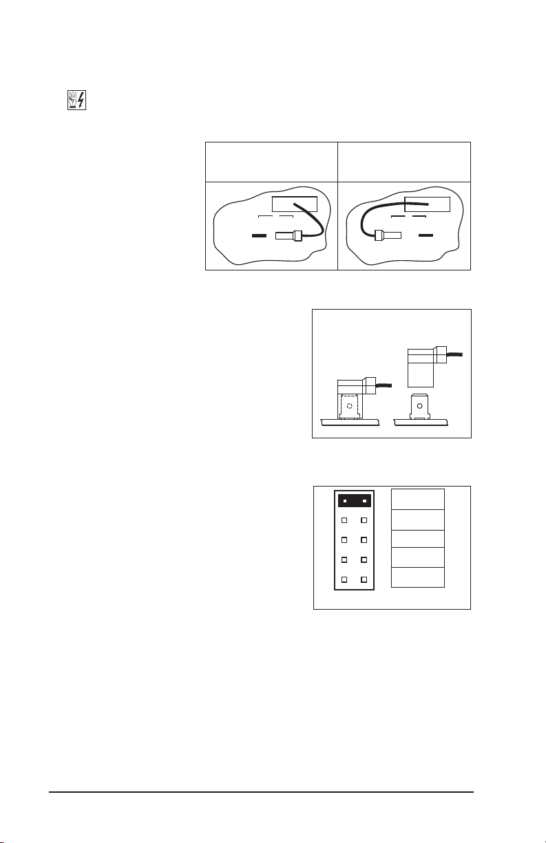
Automatic Ride-Through
(Factory Setting)
(J3 Installed in “A”Position)
Manual Start
(J3 Installed in “M”Position)
A
J3
M
A
J3
M
Figure 17 – Automatic Ride-Through
or Manual Start Selection*
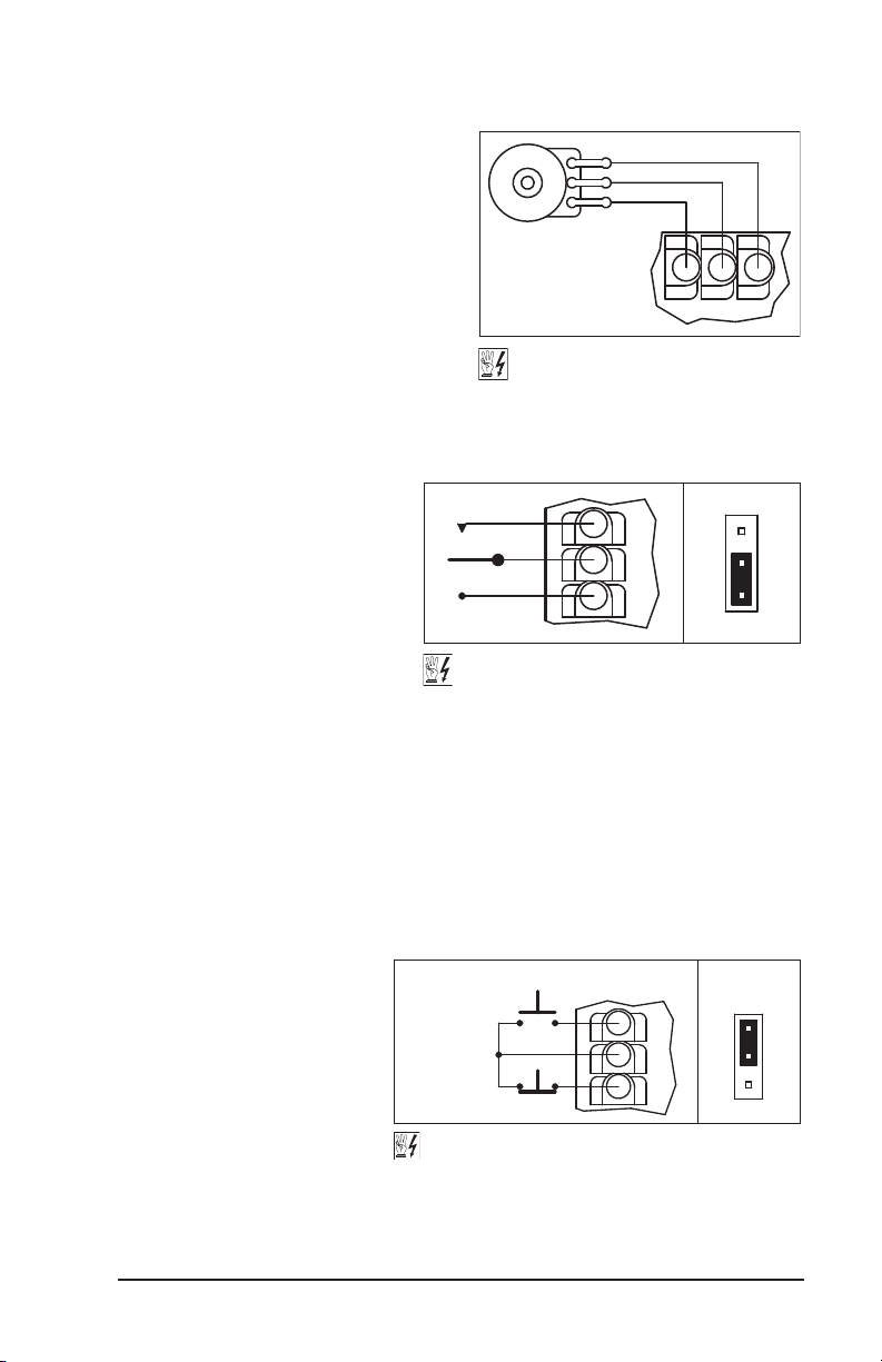
60 Hz Motor Operation
(Factory Setting)
(J4 Installed in “1X”Position)
(J5 Installed in “60Hz” Position)
50 Hz Motor Operation
(J4 Installed in “1X”Position)
(J5 Installed in “50Hz” Position)
50Hz
J5
60Hz
2X
J4
1X
50Hz
J5
60Hz
2X
J4
1X
Figure 18 – 60 Hz & 50 Hz Motor Selection
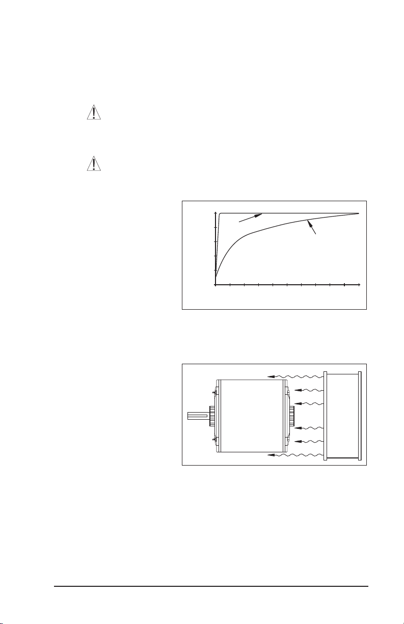
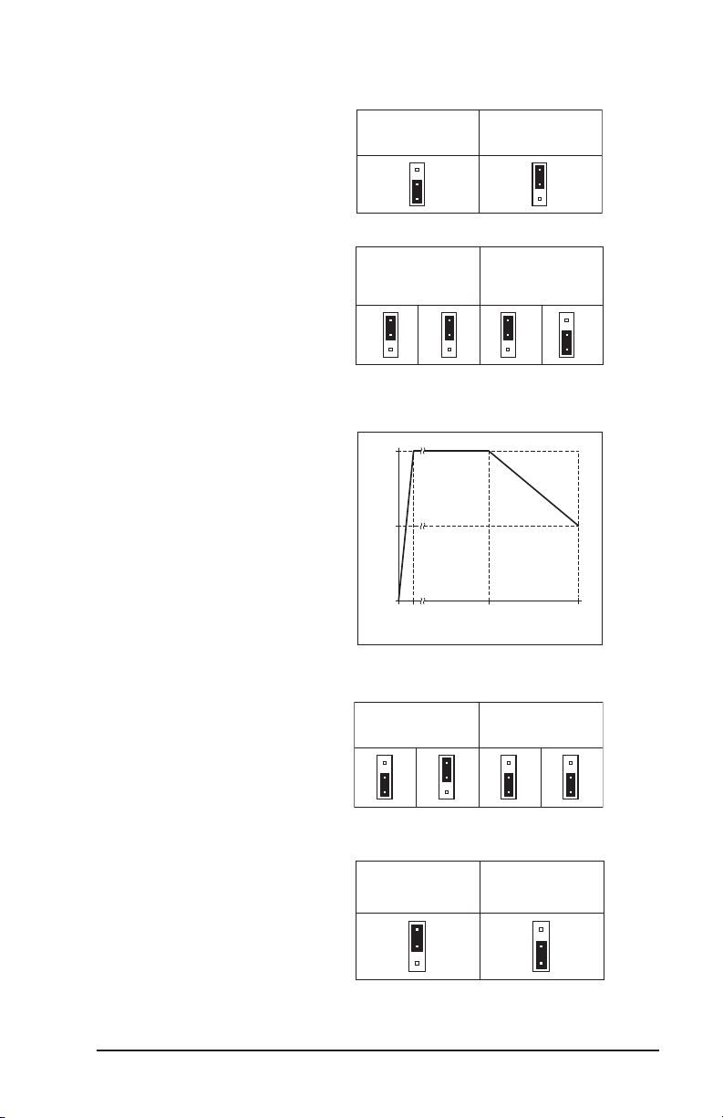
50/60
020
50
Figure 19 – Available Torque vs.
Output Frequency
120 Hz Output with 60 Hz Motor
(J4 Installed in “2X”Position)
(J5 Installed in “60Hz” Position)
100 Hz Output with 50 Hz Motor
(J4 Installed in “2X”Position)
(J5 Installed in “50Hz” Position)
50Hz
J5
60Hz
2X
J4
1X
50Hz
J5
60Hz
2X
J4
1X
Figure 20 – 120 Hz & 100 Hz Drive Output
Frequency Selection
Fixed Boost
(Factory Setting)
(J6 Installed in “FIX”Position)
Adjustable Boost
(J6 Installed in “ADJ” Position)
ADJ
J6
FIX
ADJ
J6
FIX
Figure 21 –
Fixed or Adjustable Boost Selection