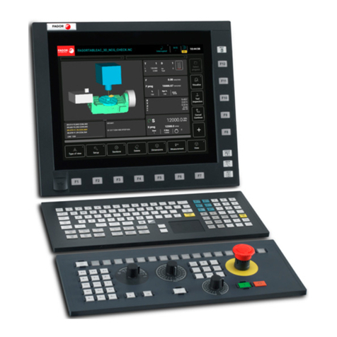
Fagor CNC 8070 User manual

(Ref: 1505)
8070
CNC
Operating manual

All rights reserved. No part of this documentation may be transmitted,
transcribed, stored in a backup device or translated into another language
without Fagor Automation’s consent. Unauthorized copying or distributing of this
software is prohibited.
The information described in this manual may be changed due to technical
modifications. Fagor Automation reserves the right to make any changes to the
contents of this manual without prior notice.
All the trade marks appearing in the manual belong to the corresponding owners.
The use of these marks by third parties for their own purpose could violate the
rights of the owners.
It is possible that CNC can execute more functions than those described in its
associated documentation; however, Fagor Automation does not guarantee the
validity of those applications. Therefore, except under the express permission
from Fagor Automation, any CNC application that is not described in the
documentation must be considered as "impossible". In any case, Fagor
Automation shall not be held responsible for any personal injuries or physical
damage caused or suffered by the CNC if it is used in any way other than as
explained in the related documentation.
The content of this manual and its validity for the product describedhere has been
verified. Even so, involuntary errors are possible, thus no absolute match is
guaranteed. Anyway, the contents of the manual is periodically checked making
and including the necessary corrections in a future edition. We appreciate your
suggestions for improvement.
The examples described in this manual are for learning purposes. Before using
them in industrial applications, they must be properly adapted making sure that
the safety regulations are fully met.
MACHINE SAFETY
It is up to the machine manufacturer to make sure that the safety of the machine
is enabled in order to prevent personal injury and damage to the CNC or to the
products connected to it. On start-up and while validating CNC parameters, it
checks the status of the following safety elements. If any of them is disabled, the
CNC shows a warning message.
• Feedback alarm for analog axes.
• Software limits for analog and sercos linear axes.
• Following error monitoring for analog and sercos axes (except the spindle)
both at the CNC and at the drives.
• Tendency test on analog axes.
FAGOR AUTOMATION shall not be held responsible for any personal injuries or
physical damage caused or suffered by the CNC resulting from any of the safety
elements being disabled.
HARDWARE EXPANSIONS
FAGOR AUTOMATION shall not be held responsible for any personal injuries or
physical damage caused or suffered by the CNC resulting from any hardware
manipulation by personnel unauthorized by Fagor Automation.
If the CNC hardware is modified by personnel unauthorized by Fagor Automation,
it will no longer be under warranty.
COMPUTER VIRUSES
FAGOR AUTOMATION guarantees that the software installed contains no
computer viruses. It is up to the user to keep the unit virus free in order to
guarantee its proper operation. Computer viruses at the CNC may cause it to
malfunction.
FAGOR AUTOMATION shall not be held responsible for any personal injuries or
physical damage caused or suffered by the CNC due a computer virus in the
system.
If a computer virus is found in the system, the unit will no longer be under warranty.
DUAL-USE PRODUCTS
Products manufactured by FAGOR AUTOMATION since April 1st 2014 will
include "-MDU" in their identification if they are included on the list of dual-use
products according to regulation UE 428/2009 and require an export license
depending on destination.

Operating manual
CNC 8070
(REF: 1505)
·3·
INDEX
About the product ......................................................................................................................... 9
Declaration of conformity............................................................................................................ 11
Version history ............................................................................................................................ 13
Safety conditions ........................................................................................................................ 23
Warranty terms ........................................................................................................................... 27
Material returning terms.............................................................................................................. 29
CNC maintenance ...................................................................................................................... 31
CHAPTER 1 DESCRIPTION OF THE KEYS
1.1 Monitor LCD-15. ............................................................................................................ 33
1.2 Monitor LCD-10K. ......................................................................................................... 34
1.3 HORIZONTAL KEYB / HORIZONTAL KEYB + MOUSE. ........................................ 36
1.4 VERTICAL KEYB / VERTICAL KEYB + MOUSE. .................................................... 37
1.5 OP PANEL / OP PANEL + SPDL RATE. ................................................................. 38
1.6 Keyboard shortcuts. ....................................................................................................... 39
CHAPTER 2 GENERAL CONCEPTS
2.1 Turning the CNC on and off........................................................................................... 41
2.1.1 Emergency shutdown with battery ............................................................................. 43
2.2 Work modes and software protection at the CNC.......................................................... 44
2.3 Ethernet. ....................................................................................................................... 47
2.4 USB. .............................................................................................................................. 47
CHAPTER 3 HOW TO OPERATE THE CNC
3.1 General description of the interface. .............................................................................. 49
3.2 Detailed description of the CNC status bar.................................................................... 50
3.2.1 Channel synchronization window............................................................................... 51
3.2.2 PLC messages........................................................................................................... 52
3.3 Horizontal softkey menu ................................................................................................ 53
3.4 Operating modes ........................................................................................................... 54
3.4.1 Description of the various operating modes............................................................... 56
3.5 Task window ..................................................................................................................58
3.6 Windows for warnings and errors .................................................................................. 59
3.6.1 CNC warnings and errors........................................................................................... 59
3.6.2 PLC errors.................................................................................................................. 60
3.7 File selection window ..................................................................................................... 61
3.8 Calculator....................................................................................................................... 63
3.8.1 Defining expressions.................................................................................................. 65
3.9 Dialog boxes .................................................................................................................. 67
CHAPTER 4 AUTOMATIC MODE
4.1 Interface description....................................................................................................... 69
4.1.1 Softkey menus. .......................................................................................................... 71
4.2 Display the status of the program or of the active subroutines. ..................................... 72
4.3 Program simulation and execution................................................................................. 73
4.3.1 Select program........................................................................................................... 73
4.3.2 Select the first and last blocks of the execution. ........................................................ 74
4.3.3 Execute a program..................................................................................................... 77
4.3.4 Resume the execution of a program from the block where it was canceled. ............. 78
4.3.5 Cancel the execution and resume from another block while keeping the history. ..... 79
4.3.6 Simulated execution of a program. ............................................................................ 80
4.3.7 Execute a program (retrace). ..................................................................................... 83
4.3.8 Executing a program in 8055 MC/TC language. ........................................................ 86
4.4 Executing program blocks separately. ........................................................................... 87
4.5 Tool inspection. ............................................................................................................. 88
4.5.1 Tool inspection (execution in retrace mode, independent interpolator or rigid tapping).
91
4.6 Block search. ................................................................................................................. 93
4.6.1 Treatment of functions M, H, F, S. ............................................................................. 95
4.7 Show/hide the dynamic override of the HSC. ................................................................ 96

·4·
Operating manual
CNC 8070
(REF: 1505)
CHAPTER 5 MANUAL (JOG) MODE
5.1 Interface description. ..................................................................................................... 97
5.1.1 Softkey menus. .......................................................................................................... 99
5.2 Operations with the axes. ............................................................................................ 100
5.2.1 Home search............................................................................................................ 100
5.2.2 Jog ........................................................................................................................... 101
5.2.3 Jogging the axes with handwheels .......................................................................... 103
5.2.4 Moving an axis to a particular position (coordinate)................................................. 105
5.2.5 Coordinate preset .................................................................................................... 105
5.3 Spindle control ............................................................................................................. 106
5.4 Tool selection and tool change .................................................................................... 107
5.5 Setting the feedrate and spindle speed. ...................................................................... 108
5.6 Setting and activating the zero offsets and the fixture offsets. .................................... 109
CHAPTER 6 MANUAL (JOG) MODE. TOOL CALIBRATION
6.1 Manual calibration. Calibration without a probe........................................................... 113
6.2 Semi-automatic calibration. Calibration with a probe................................................... 117
6.3 Automatic calibration with a probe and a canned cycle............................................... 120
6.3.1 Mill or lathe model ("trihedron" geometrical configuration)....................................... 120
6.3.2 Lathe model ("plane" geometrical configuration) ..................................................... 123
CHAPTER 7 MANUAL (JOG) MODE. PART CENTERING (MILL MODEL)
7.1 How to define the data................................................................................................. 126
7.2 Data programming. ...................................................................................................... 127
7.3 Basic operation. ........................................................................................................... 130
CHAPTER 8 EDISIMU MODE (EDITING AND SIMULATION)
8.1 Interface description. ................................................................................................... 133
8.1.1 Softkey menus. ........................................................................................................ 135
8.2 Program editing and simulation ................................................................................... 136
8.2.1 Program editing........................................................................................................ 136
8.2.2 Editing a program in the 8055 CNC language ......................................................... 137
8.2.3 Program simulation .................................................................................................. 139
8.2.4 Simulation errors...................................................................................................... 141
8.3 Editing window............................................................................................................. 142
8.3.1 Softkey and hotkey menus....................................................................................... 144
8.3.2 Contextual programming assistance........................................................................ 145
8.3.3 Help for programming subroutines........................................................................... 146
8.3.4 Syntax errors when editing ...................................................................................... 147
8.4 Working in the editing window. .................................................................................... 148
8.4.1 Select a program...................................................................................................... 148
8.4.2 Operations with blocks. Cut and paste. ................................................................... 149
8.4.3 Find a line or a text in the program. ......................................................................... 150
8.4.4 Undo and redo. ........................................................................................................ 151
8.4.5 Operations with files................................................................................................. 152
8.4.6 Customizing the editor. ............................................................................................ 153
8.4.7 TEACH-IN ................................................................................................................ 155
8.4.8 Import DXF files ....................................................................................................... 156
8.4.9 Profile editor.............................................................................................................158
8.4.10 Canned cycle editor. ................................................................................................ 159
8.4.11 Inclined planes (·M· model)...................................................................................... 160
8.4.12 Geometric-help editor (·M· model) ........................................................................... 161
8.5 Graphic assistance for the program editor................................................................... 162
8.6 Graphics window ......................................................................................................... 163
8.7 Program window .......................................................................................................... 164
8.8 Working in the program window. ................................................................................. 165
8.8.1 Select the first and last blocks of the execution. ...................................................... 165
8.8.2 Simulate program blocks separately........................................................................ 166
8.8.3 Display the status of the program or of the active subroutines. ............................... 167
8.9 Statistics window ......................................................................................................... 168
8.9.1 Time estimates......................................................................................................... 169
CHAPTER 9 PROFILE EDITOR
9.1 Interface description. ................................................................................................... 171
9.1.1 How to use the profile editor. ................................................................................... 173

Operating manual
CNC 8070
(REF: 1505)
·5·
9.2 Define a new profile, enlarge an existing one or import one from a file. ...................... 174
9.2.1 Define any profile using straight and curved sections.............................................. 175
9.2.2 Define a circular profile. ........................................................................................... 177
9.2.3 Define a rectangular profile. ..................................................................................... 178
9.2.4 Enlarge a profile. ...................................................................................................... 178
9.2.5 Import a profile from a DXF file. ............................................................................... 179
9.3 Modify a profile and insert corners............................................................................... 181
9.4 Configuring the profile editor. Displayed area.............................................................. 183
9.5 Configuring the profile editor. Define the work plane................................................... 183
9.6 End the session at the editor. ...................................................................................... 183
9.7 Examples of how to define profiles. ............................................................................. 184
9.7.1 Profile editor. Example 1 (milling). ........................................................................... 184
9.7.2 Profile editor. Example 2 (milling). ........................................................................... 185
9.7.3 Profile editor. Example 3 (milling). ........................................................................... 187
9.7.4 Profile editor. Example 4 (lathe)............................................................................... 188
CHAPTER 10 GRAPHIC ENVIRONMENT (MILL MODEL)
10.1 Description of the graphic environment. ...................................................................... 189
10.1.1 Softkey menus. ........................................................................................................ 190
10.2 Type of graphics .......................................................................................................... 191
10.3 Zoom............................................................................................................................ 192
10.4 Dimensions ..................................................................................................................193
10.5 Point of view................................................................................................................. 193
10.6 Measurement ............................................................................................................... 194
10.7 Clear screen................................................................................................................. 195
10.8 Colors........................................................................................................................... 195
10.9 Options......................................................................................................................... 196
10.10 Real coordinates .......................................................................................................... 197
10.11 Real coordinates with enlarged error ........................................................................... 197
10.12 Simulation speed ......................................................................................................... 197
CHAPTER 11 HD GRAPHIC ENVIRONMENT (MILL MODEL)
11.1 Description of the graphic environment. ...................................................................... 199
11.1.1 Softkey menus. ........................................................................................................ 200
11.2 Move, rotate and zoom in or out on the graphic. ......................................................... 201
11.3 Select the type of view. ................................................................................................ 202
11.4 Configure the graphics (number of windows, colors, etc.). .......................................... 203
11.5 Actions (move sections and print graphics). ................................................................ 206
11.6 Delete the graphic........................................................................................................ 207
11.7 Define the dimensions of the parts and the size of the graphic. .................................. 207
11.8 Measure the part.......................................................................................................... 208
11.9 Simulation speed. ........................................................................................................ 208
CHAPTER 12 GRAPHIC ENVIRONMENT (LATHE MODEL)
12.1 Description of the graphic environment. ...................................................................... 209
12.1.1 Softkey menus. ........................................................................................................ 210
12.2 Type of graphics .......................................................................................................... 211
12.3 Zoom............................................................................................................................ 212
12.4 Dimensions ..................................................................................................................213
12.5 Measurement ............................................................................................................... 213
12.6 Clear screen................................................................................................................. 214
12.7 Colors........................................................................................................................... 214
12.8 Options......................................................................................................................... 215
12.9 Real coordinates .......................................................................................................... 216
12.10 Real coordinates with enlarged error ........................................................................... 216
12.11 Simulation speed ......................................................................................................... 216
CHAPTER 13 HD GRAPHIC ENVIRONMENT (LATHE MODEL)
13.1 Description of the graphic environment. ...................................................................... 217
13.1.1 Softkey menus. ........................................................................................................ 218
13.2 Move, rotate and zoom in or out on the graphic. ......................................................... 219
13.3 Select the type of view. ................................................................................................ 220
13.4 Configure the graphics (number of windows, colors, etc.). .......................................... 221
13.5 Actions (move sections and print graphics). ................................................................ 224
13.6 Delete the graphic........................................................................................................ 225
13.7 Define the dimensions of the parts and the size of the graphic. .................................. 225
13.8 Measure the part.......................................................................................................... 226
13.9 Simulation speed. ........................................................................................................ 226

·6·
Operating manual
CNC 8070
(REF: 1505)
CHAPTER 14 MDI/MDA MODE
14.1 Interface description. ................................................................................................... 227
14.1.1 Softkey menus. ........................................................................................................ 228
14.2 Edit and execute individual blocks............................................................................... 229
14.3 Block history. ............................................................................................................... 230
CHAPTER 15 USER TABLES
15.1 User table presentation................................................................................................ 231
15.1.1 Softkey menus. ........................................................................................................ 232
15.2 Zero offset tables ......................................................................................................... 233
15.3 Fixture table ................................................................................................................. 235
15.4 Arithmetic parameter tables......................................................................................... 236
15.5 Operations with tables ................................................................................................. 238
15.5.1 Data editing..............................................................................................................238
15.5.2 Save and recall tables.............................................................................................. 239
15.5.3 Find text. ................................................................................................................. 240
CHAPTER 16 TOOL AND MAGAZINE TABLE
16.1 Presentation of the tool tables and magazine tables. ................................................. 241
16.1.1 Softkey menus. ........................................................................................................ 242
16.1.2 Search for a text in the tables .................................................................................. 243
16.1.3 Save and load the tables ......................................................................................... 244
16.1.4 Printing the tables .................................................................................................... 246
16.2 Tool table ..................................................................................................................... 247
16.3 Tool and tool magazine table....................................................................................... 249
16.3.1 Vertical softkey menu............................................................................................... 249
16.3.2 The tool list............................................................................................................... 250
16.3.3 Description of the tool data ...................................................................................... 251
16.4 Tool table (simple mode). ............................................................................................ 259
16.4.1 Vertical softkey menu............................................................................................... 259
16.4.2 Configuring the tool data display.............................................................................. 259
16.4.3 Data of the M tools (standard page - screen-). ........................................................ 260
16.4.4 Data of the T tools (standard page - screen-). ......................................................... 261
16.4.5 Data of the M/T tools (offset page - screen-). .......................................................... 262
16.4.6 Editing the tool table. ............................................................................................... 262
16.5 Operations with the tool table (full mode). ................................................................... 263
16.5.1 Editing the tool table ................................................................................................ 263
16.6 Active-tools table ......................................................................................................... 264
16.6.1 Softkey menus. ........................................................................................................ 265
16.6.2 Changing the tool of the spindle .............................................................................. 265
16.7 Table for the status of the tool change process........................................................... 266
16.8 Magazine table ............................................................................................................ 267
16.8.1 Softkey menus. ........................................................................................................ 268
16.8.2 List of magazine positions........................................................................................ 269
16.8.3 Magazine information............................................................................................... 270
16.9 Operations with the magazine table ............................................................................ 272
16.9.1 Loading / unloading tools to / from the magazine .................................................... 272
16.9.2 Load / unload a tool to / from the tool changer arm ................................................. 274
CHAPTER 17 UTILITIES MODE
17.1 Interface description. ................................................................................................... 275
17.1.1 Softkey menus. ........................................................................................................ 277
17.2 Set how to display the list of programs. ....................................................................... 278
17.3 Select files and create folders...................................................................................... 279
17.4 Search in files .............................................................................................................. 280
17.5 Protection passwords .................................................................................................. 281
17.6 Data safety backup. Backup - Restore ........................................................................ 283
17.7 Encrypting files ............................................................................................................285
CHAPTER 18 PLC
18.1 Appearance of the PLC mode ..................................................................................... 287
18.1.1 Icon description (vertical softkeys)........................................................................... 288
18.2 "Programs" service ...................................................................................................... 289
18.2.1 Softkey menus. PLC project. ................................................................................... 290
18.2.2 Softkey menus. Files of the PLC project.................................................................. 291
18.3 Program editing ........................................................................................................... 292

Operating manual
CNC 8070
(REF: 1505)
·7·
18.4 Editing in C language or mnemonic language. ............................................................ 294
18.4.1 Softkey "Analyze"..................................................................................................... 295
18.4.2 Softkey "File". ..........................................................................................................295
18.4.3 Softkey "Undo". ........................................................................................................ 295
18.4.4 Softkey "Operations with blocks". ............................................................................ 296
18.4.5 Softkey "Find/Replace". ........................................................................................... 297
18.4.6 Softkey "Customize"................................................................................................. 298
18.5 Editing in contact (ladder) language (softkeys)............................................................ 299
18.5.1 Softkey "Analyze"..................................................................................................... 300
18.5.2 Softkey "File". ..........................................................................................................300
18.5.3 "Edit" softkey. ..........................................................................................................301
18.5.4 Softkey "View". ........................................................................................................ 303
18.5.5 Softkey "Marks". ...................................................................................................... 303
18.5.6 Softkey "Find"........................................................................................................... 304
18.5.7 Softkey "Customize"................................................................................................. 304
18.6 Program monitoring ..................................................................................................... 305
18.6.1 Softkey menus. Monitoring in C language or mnemonic language. ........................ 306
18.6.2 Softkey menus. Monitoring in contact (ladder) language. ....................................... 307
18.7 "Commands" service.................................................................................................... 309
18.7.1 Softkey menus. Options of the "Commands" service............................................... 309
18.8 "Outputs" service ......................................................................................................... 310
18.8.1 Softkey menus. Options of the "Outputs" service. ................................................... 311
18.9 "Logic analyzer" service............................................................................................... 312
18.9.1 Editing logic analyzer data ....................................................................................... 313
18.9.2 Save, load and reset the analyzer configuration...................................................... 315
18.9.3 Execute and analyze trace....................................................................................... 316
18.9.4 Customize the appearance of the logic analyzer ..................................................... 316
18.10 "Monitoring" service ..................................................................................................... 317
18.10.1 Description of resource tables.................................................................................. 318
18.10.2 Definition of the table resources............................................................................... 319
18.10.3 Options of the "Monitoring" service (softkeys). ........................................................ 320
18.11 "Cross references" service........................................................................................... 321
18.11.1 Softkey menus. Options of the "Cross reference" service. ...................................... 322
18.12 "Statistics" service........................................................................................................ 323
18.12.1 Softkey menus. Options of the "Statistics" service................................................... 324
18.13 "Messages" service...................................................................................................... 325
18.13.1 Softkey menus. Options of the "Messages" service................................................. 326
18.13.2 Editing the message and error table ........................................................................ 327
18.13.3 Displaying PLC messages ....................................................................................... 328
18.13.4 Displaying PLC errors .............................................................................................. 329
18.13.5 Grouping the additional information text files in a single file. ................................... 330
18.13.6 Save, load and print a message and error table ...................................................... 331
CHAPTER 19 MACHINE PARAMETERS
19.1 Appearance of the machine parameter tables ............................................................. 333
19.1.1 Softkey menus. ........................................................................................................ 334
19.2 Parameter table description ......................................................................................... 335
19.2.1 "M" function setting table.......................................................................................... 336
19.2.2 Compensation table ................................................................................................. 337
19.2.3 Kinematics table....................................................................................................... 338
19.2.4 OEM parameters...................................................................................................... 339
19.3 Operations with tables ................................................................................................. 340
19.3.1 Data editing and validation....................................................................................... 340
19.3.2 Save and recall tables.............................................................................................. 341
19.3.3 Find text. ................................................................................................................. 342
19.3.4 Importing and exporting compensation tables. ........................................................ 343
CHAPTER 20 SETUP ASSISTANCE
20.1 Oscilloscope................................................................................................................. 346
20.1.1 Interface description................................................................................................. 347
20.1.2 Softkey menus. ........................................................................................................ 348
20.1.3 Configuration screen ................................................................................................ 351
20.1.4 Configure and execute the oscilloscope function..................................................... 352
20.1.5 Machine parameter editing. ..................................................................................... 353
20.2 The Bode diagram ....................................................................................................... 356
20.2.1 Interface description................................................................................................. 357
20.2.2 Softkey menus. ........................................................................................................ 358
20.2.3 Machine parameter editing. ..................................................................................... 361
20.2.4 Configuration screen ................................................................................................ 363

·8·
Operating manual
CNC 8070
(REF: 1505)
20.3 The circularity (roundness) test ................................................................................... 366
20.3.1 Interface description................................................................................................. 367
20.3.2 Softkey menus. ........................................................................................................ 369
20.3.3 Configuring and executing the circularity (roundness) test ...................................... 370
20.3.4 Configure the graphic environment.......................................................................... 371
20.3.5 Define and execute the movement subroutine ........................................................ 372
20.3.6 Data capture for the graphic .................................................................................... 373
20.3.7 Adjustment of the machine parameters involved ..................................................... 374
20.3.8 Validate the changes and save the configuration used ........................................... 376
20.3.9 Machine parameters that may be modified.............................................................. 377
CHAPTER 21 DDSSETUP
21.1 Appearance of the DDSSetup mode ........................................................................... 379
21.1.1 Icon description (vertical softkeys)........................................................................... 380
21.2 List of devices connected to the bus............................................................................ 381
21.3 Drives accessing level (only Sercos). .......................................................................... 383
21.4 –Parameters and variables– service. .......................................................................... 384
21.5 –Error management– service. ..................................................................................... 386
21.6 –Monitoring– service.................................................................................................... 387
21.7 –Information– service .................................................................................................. 389
21.8 Command generator (only Sercos). ............................................................................ 391
21.9 Command line.............................................................................................................. 392
21.10 File for setting the parameters of Mechatrolink servos. ............................................... 394
CHAPTER 22 DIAGNOSIS
22.1 Appearance of the diagnosis mode. ............................................................................ 397
22.1.1 Softkey menus. ........................................................................................................ 398
22.2 Configuration diagnosis ............................................................................................... 399
22.2.1 System diagnosis..................................................................................................... 399
22.2.2 Software diagnosis................................................................................................... 400
22.2.3 Hardware diagnosis. Bus CAN, Sercos and Mechatrolink....................................... 401
22.3 Sercos diagnosis ......................................................................................................... 403
22.4 Save the CAN configuration for the start-up test. ........................................................ 404
22.5 Report generation ........................................................................................................ 405
22.6 View the history of errors and warnings issued by the CNC........................................ 406
22.7 Generating the Fagor file for error diagnosis. .............................................................. 406
22.8 Access particular utilities of the operative system and other applications. .................. 406
CHAPTER 23 APPS
23.1 Send emails. ................................................................................................................408
23.1.1 Configure and activate the application. .................................................................... 410
23.1.2 Configuring network properties. ............................................................................... 412

Operating manual
CNC 8070
(REF: 1505)
·9·
ABOUT THE PRODUCT
BASIC CHARACTERISTICS.
(*) Differential TTL / Sinusoidal 1 Vpp (**) TTL / Differential TTL / Sinusoidal 1 Vpp / SSI protocol
Basic characteristics. ·BL· ·OL·
PC-based system. Closed system Open system
Number of axes. 3 to 7 3 to 28
Number of spindles. 1 1 to 4
Number of tool magazines. 1 1 to 4
Number of execution channels. 1 1 to 4
Number of handwheels. 1 to 12
Type of servo system. Analog / Digital Sercos / Digital Mechatrolink
Communications. RS485 / RS422 / RS232
Ethernet
PCI expansion. No Option
Integrated PLC.
PLC execution time.
Digital inputs / Digital outputs.
Marks / Registers.
Timers / Counters.
Symbols.
< 1ms/K
1024 / 1024
8192 / 1024
512 / 256
Unlimited
Block processing time. < 1 ms
Remote modules. RIOW RIO5 RIO70 RIOR RCS-S
Valid for CNC. 8070
8065
8060
8070
8065
8060
8070
8065
- - -
- - -
- - -
8060
8070
8065
8060
Communication with the remote modules. CANopen CANopen CANfagor CANopen Sercos
Digital inputs per module. 8 24 / 48 16 48 - - -
Digital outputs per module. 8 16 / 32 16 32 - - -
Analog inputs per module. 4 4 8 - - - - - -
Analog outputs per module. 4 4 4 - - - 4
Inputs for PT100 temperature sensors. 2 2 - - - - - - - - -
Feedback inputs. - - - - - - 4 (*) - - - 4 (**)
Customizing.
PC-based open system, fully customizable.
INI configuration files.
FGUIM visual configuration tool.
Visual Basic®, Visual C++®, etc.
Internal databases in Microsoft® Access.
OPC compatible interface

·10·
Operating manual
CNC 8070
(REF: 1505)
SOFTWARE OPTIONS.
Bear in mind that some of the features described in this manual depend on the software options that are
installed. The information of the following table is informative only; when purchasing the software options,
only the information provided in the ordering handbook is valid.
-BL- model -OL- model
Open system.
Access to the administrator mode.
- - - Option
Editing and simulation environment. - - - Standard
Number of execution channels 1 1 to 4
Number of axes 3 to 7 3 to 28
Number of spindles 1 1 to 4
Number of tool magazines 1 1 to 4
Number of interpolated axes (maximum) 4 28
Limited to 4 interpolated axes - - - Option
IEC 61131 language - - - Option
Non-Fagor digital drive Option Option
Tool radius compensation Option Option
"C" axis Option Option
Dynamic RTCP Option Option
HSSA machining system. Option Option
Drilling ISO cycles for the OL model.
(G80, G81, G82, G83).
- - - Option
Tandem axes - - - Option
Synchronism and cams Option Option
Tangential control Option Option
Volumetric compensation (up to 10 m³). - - - Option
Volumetric compensation (more than 10 m³). - - - Option
PWM (Pulse-Width Modulation). - - - Option

Operating manual
CNC 8070
(REF: 1505)
·11·
DECLARATION OF CONFORMITY
The manufacturer:
Fagor Automation S. Coop.
Barrio de San Andrés Nº 19, C.P.20500, Mondragón -Guipúzcoa- (Spain).
Declares:
The manufacturer declares under their exclusive responsibility the conformity of the product:
8070 CNC
Consisting of the following modules and accessories:
8070-BL-ICU, 8070-OL-ICU
8070-BL-MCU, 8070-OL-MCU , 8070-OL-MCU-PCI
MONITOR-LCD-10K, MONITOR-LCD-15, MONITOR-SVGA-15
HORIZONTAL-KEYB, VERTICAL-KEYB, OP-PANEL
BATTERY, MOUSE UNIT
Remote Modules RIOW, RIO5, RIO70, RCS-S.
Note.Some additional characters may follow the model references indicated above. They all comply with the
directives listed here. However, compliance may be verified on the label of the unit itself.
Referred to by this declaration with following directives:
According to the European Community Directives 2006/95/EC on Low Voltage and 2004/108/EC
on Electromagnetic Compatibility and their updates.
In Mondragón, September 1st, 2013.
Low-voltage regulations.
IEC 60204-1:2005/A1:2008 Electrical equipment on machines. Part1. General requirements.
Regulation on electromagnetic compatibility.
EN 61131-2: 2007 PLC. Part 2. Equipment requirements and tests.


Operating manual
CNC 8070
(REF: 1505)
·13·
VERSION HISTORY
Here isa listof thefeaturesadded toeach manualreference.Eachmanual reference isvalid forthe indicated
software version and newer versions.
Ref. 0201
Ref. 0212
Ref. 0501
Software V01.00
First version. Milling model.
Software V01.10
New repositioning feedrate after tool inspection. • Machine parameter: REPOSFEED.
New treatment of the JOG keys. Different keys to select the axis and the
direction.
• Machine parameter: JOGKEYDEF.
Know the dimensions of the kinematics on an axis. • Variable: (V.)A.HEADOF.xn
Keyboard simulation from the PLC. • Variable: (V.)G.KEY
Manual (jog) mode. Tool calibration with or without probe.
Manual (jog) mode. Automatic loading of zero offsets table.
Manual (jog) mode. Programming of feedrate "F" and spindle speed "S".
MDI mode. Block syntax check.
Utilities mode. Define protection passwords.
Block search. Define the first block.
Improved tool table.
Axis selection/deselection to move it with a handwheel.
Simulate the theoretical path.
Confirm the execution of a program pressing the [START] key in a mode other
than automatic.
General scaling factor. • New instruction, #SCALE.
Probe selection. • New instruction, #SELECT PROBE.
Probing canned cycles. • New instruction, #PROBE.
Programming of warnings. • New instruction, #WARNING.
Block repetition. • New instruction, #RPT.
Know the active general scaling factor. • Variable: (V.)G.SCALE
Knowing which is the active probe. • Variable: (V.)G.ACTIVPROBE
Improved programming of high speed machining. • #HSC instruction.
Improved programming of axis swapping. • Instructions #SET, #CALL, #FREE, #RENAME.
The number of macros in a program is now limited to 50. • Macros.
Software V02.01
Windows XP operating system.
Emergency shutdown with battery (central unit PC104).
Multi-channel system, up to 4 channels. Swapping of axes and spindles,
communication and synchronization between channels, common arithmetic
parameters, access variables by channel, etc.
Multi-spindle system, up to 4 spindles.
Tool management with up to 4 magazines.
New languages (Basque and Portuguese). • Machine parameter: LANGUAGE.
Placing the vertical softkeys on the left or on the right. • Machine parameter: VMENU.
Tool radius compensation mode (G136/G137) by default • Machine parameter: IRCOMP.
OEM generic machine parameters. • Machine parameter: MTBPAR.
Reading Sercos variables from the CNC. • Machine parameter: DRIVEVAR.
Electronic-cam editor. • Machine parameter: CAM.
New behavior for rotary axes.
The "(V.).TM.MZWAIT " variable is not necessary in the subroutine associated
with M06.
• Subroutine associated with M6.
• Variable: (V.).TM.MZWAIT
Know the software version. • Variable: (V.)G.SOFTWARE
Variables related to loop adjustment. Gain setting via PLC. • Variables:
(V.)A.PLCFFGAIN.xn (V.)A.PLCACFGAIN.xn
(V.)A.PLCPROGAIN.xn
Variables related to loop adjustment. Position increment and sampling period. • Variables:
(V.)A.POSINC.xn (V.)A.TPOSINC.xn
(V.)A.PREVPOSINC.xn

·14·
Operating manual
CNC 8070
(REF: 1505)
Ref. 0504
Ref. 0509
Variables related to loop adjustment. Fine adjustmentoffeedrate, acceleration
and jerk.
• Variables:
(V.)A.FEED.xn (V.)A.TFEED.xn
(V.)A.ACCEL.xn (V.)A.TACCEL.xn
(V.)A.JERK.xn (V.)A.TJERK.xn
Variables related to the feedback inputs. • Variables:
(V.)A.COUNTER.xn (V.)A.COUNTERST.xn
(V.)A.ASINUS.xn (V.)A.BSINUS.xn
Optimize the reading and writing of variables from the PLC. Only the access
to the following variables will be asynchronous.
• The tool variables will be read asynchronously when the tool is neither the
active one nor in the magazine.
• The tool variables will be written asynchronously whether the tool is the
active one or not.
• The variables referred to local arithmetic parameters of the active levels
will be read and written asynchronously.
• Reading and writing of variables from the PLC.
Spindle parking and unparking. • Instructions #PARK, #UNPARK.
Tool radius compensation.
• Behavior of the beginning and end of tool radius compensation when not
programming a movement.
• Changing the type of radius compensation while machining.
Via program, loading a tool in a specific magazine position.
Programming of modal subroutines. • New instruction, #MCALL.
Executing a block in a channel. • New instruction, #EXBLK.
Programming the number of repetitions in the block. • NR command.
Direct resolution of 2D and 3D pockets without requiring a softkey.
Simulating a canned cycle of the editor separately.
Importing DXF files from the program editor or from the profile editor.
Importing programs of the 8055/8055i CNC from the program editor.
Use a softkey to select the repositioning of the spindle after tool inspection.
Backup-restore utility.
Improved profile editor.
Assistance in the program editor. Contextual programming assistance.
• When programming "#", it shows the list of instructions.
• When programming "$", it shows the list of instructions.
• When programming "V.", it shows the list of variables.
Specific password for the machine parameters for kinematics.
Save the CAN configuration for testing it when starting up the system.
The diagnosis mode shows detailed information on the Sercos connection
(Type and version of the drive and motor connected to it).
It is possible to print all the information on the configuration from any section
of the diagnosis mode.
It is possible to simulate a cycle separately from the cycle editor.
Setup assistance. Oscilloscope, Bode diagram, circularity test.
Software V02.03
New values of machine parameter SERPOWSE for the "Sercos II" board. • Machine parameters: SERPOWSE.
The simulated axes are ignored regarding the validation code.
Electronic cam programming (real coordinates). • New instruction, #CAM.
Synchronization of independent axis (real coordinates). • New instruction, #FOLLOW.
Movement of the independent axis. • New instruction, #MOVE.
DDSSetup mode.
G31. Temporary polar origin shift to the center of interpolation. • Function G31.
G112. Change the drive's parameter set. • Function G112.
Software V03.00
Lathe model. Machining canned cycles, lathe tool calibration, variables to
consult the geometry of lathe tools, etc.
Incline axis.
Permit using the G95 function in jog mode. • Machine parameter: FPRMAN.
Lathe model. Select graphics configuration. • Machine parameter: GRAPHTYPE.
Lathe model. Select axis configuration. • Machine parameter: GEOCONFIG.
Select the set of parameters for synchronization. • Machine parameter: SYNCSET.
"C" axis maintained. • Machine parameter: PERCAX.
Magazine-less system.
Ground tools for a turret magazine.
Variable to read the accumulated PLC offset. • Variable: (V.)[ch].A.ACTPLCOF.xn
Variable to obtain a linear estimation of the following error. • Variable: (V.)[ch].A.FLWEST.xn
Variables to read the instant value of feed-forward or AC-forward. • Variables:
(V.)[ch].A.ACTFFW.xn (V.)[ch].A.ACTACF.xn
Variable to know the line number of the file being executed. • Variable: (V.)[ch].G.LINEN
Variable to know what kind of cycle is active. • Variable: (V.)[ch].G.CYCLETYPEON
Variable to know the tool orientation. • Variable: (V.)[ch].G.TOOLDIR
Software V02.01

Operating manual
CNC 8070
(REF: 1505)
·15·
Ref. 0601
Ref. 0606
Variable to know whether the HSC mode is active or not. • Variable: (V.)[ch].G.HSC
Variable to know the theoretical feedrate on 3D path. • Variable: (V.)[ch].G.F3D
Variable to know the number of the warning being displayed. • Variable: (V.)[ch].G.CNCWARNING
The variable (V.)G.CNCERR is now per channel. • Variable: (V.)G.CNCERR
Select the type of loop, open or closed, for the spindle. • New instruction, #SERVO.
Spindle synchronization. • New instruction, #SYNC.
Spindle synchronization. • New instruction, #TSYNC.
Spindle synchronization. • New instruction, #UNSYNC.
Select milling cycles at a lathe model. • New instruction, #MILLCY.
Select turning cycles at a milling model. • New instruction, #LATHECY.
Define a kinematics when activating the C axis. • #CYL instruction.
Define a kinematics when activating the C axis. • #FACE instruction.
Improved coordinate transformation (#CS/#ACS).
• Keep the part zero when deactivating the transformation.
• Working with 45º spindles. Select between the two choices.
• Keep the rotation of the plane axes with MODE 6.
• Instructions #CS, #ACS.
G33. New parameter (Q1) to define the entry angle. • Function G33.
G63. Tool inspection is possible during rigid tapping. • Function G63.
Function G112 is not valid for the spindle. • Function G112.
New criteria when assuming a new master spindle in the channel.
Improved tool table.
Software V03.01
Axis slaving. Configuring the default status of an axis slaving (coupling). • Machine parameters: LINKCANCEL.
Tool radius compensation. The way tool radius is canceled. • Machine parameters: COMPCANCEL.
Screen test on power-up, if any element is missing, it restores the relevant
backup.
Editing mode. Editing programs in the 8055 CNC language.
DDSSetup mode. Saving and loading the data of all the drives at the same
time.
Using the ":" character to program a comment in a part-program.
Variables. Geometry of the lathe tools.
Variables. Number of the tool in the claws of the changer arm. • Variables:
(V.)TM.TOOLCH1[mz] (V.)TM.TOOLCH2[mz]
Automatic mode. It allows executing a program independently.
The instruction #EXEC does not issue an error if the channel is busy; the
instruction waits for the operation in progress to end.
• #EXEC instruction.
The instruction #EXBLK does not issue an error if the channel is busy; the
instruction waits for the operation in progress to end.
• #EXBLK instruction.
Software V03.10
Feedrate. Maximum machining feedrate. • Machine parameter: MAXFEED.
Feedrate. Default machining feedrate when none has been programmed. • Machine parameter: DEFAULTFEED.
The user keys may be configured as jog keys. • Machine parameter: USERKEYDEF.
Disabling a keyboard or jog panel integrated into the CAN bus. • PLC mark: PANELOFF.
Handwheel with push-button. Selecting an axis sequentially for jogging it with
the handwheel.
• PLC mark: NEXTMPGAXIS.
•
New parameter to set whether or not the CNC sends the M, H, S functions to
the PLC during block search.
• Machine parameter: FUNPLC.
The CNC allows changing the spindle override during electronic threading
(G33) and in the threading canned cycles of the ·T· model (G86, G87 and their
equivalent of the cycle editor).
• Machine parameters:
THREADOVR, OVRFILTER.
OEM machine parameters.
• Range of parameters that can be written from the part-program, from the
PLC or from the interface.
• Range of parameters affected by the change of units.
• Each parameter may have a different describing comment associated
with it.
Home search. New home searching method for spindles with home switch.
The spindle goes through the home switch twice.
The CNC displays the warnings generated at the drive.
M function table. New field to define whether the function is sent out to the PLC
or not during block search.
•Field:MPLC.
M function table. Each M function may have a different describing comment
associated with it.
• Field: COMMENT.
General handwheel. The CNC may have several general handwheels.
General handwheel. A general handwheel can move several axes at the same
time.
Improvements in the looks of some softkeys of the editor.
Improvements in the looks of some softkeys of the graphics window.
Editing mode. Programming help files for OEM and global subroutines.
Editing mode. Help file with the list of available subroutines.
Software V03.00

·16·
Operating manual
CNC 8070
(REF: 1505)
Ref. 0608
Ref. 0704 / Ref. 0706
Editing mode. Improved contextual assistance.
Editing mode. New softkey for deactivating the contextual assistance.
Editing mode. Improvements in the looks of the softkeys.
The automatic mode offers a softkey for selecting the program that is being
edited.
In automatic and jog modes, the CNC shows the status of the _FEEDHOL
mark.
• PLC mark: _FEEDHOL.
In automatic and jog modes, the CNC shows the status of the INHIBIT mark
of the axes and spindle.
• PLC mark: INHIBIT.
Automatic mode. It shows information on all the spindles.
Manual (jog) mode. It shows information on all the spindles.
"Retrace" function.
Tangential control.
Tool table. New softkey for initializing the positions; T1 in position 1, T2 in
position 2, etc.
Tool table. New softkeys for copying and pasting the data of a tool offset.
The CNC checks whether the programmed turning direction (M3/M4) matches
the one preset in the tool table.
Generating the warranty registration report.
Hiding the window for errors and warnings.
M02/M30. There is no need to program M02 or M30 to end a part program. • Functions M02/M30.
Canceling the preset turning direction of a tool. • Variables: (V.)G.SPDLTURDIR
Change the maximum feedrate allowed in the channel from the PLC. • Variables: (V.)[ch].PLC.PLCG00FEED
Show the status of the emergency relay. • Variables: (V.)G.ERELAYST
HSC. New FAST mode. • #HSC instruction.
C axis. The #CYL instruction requires programming the radius. • #CYL instruction.
Improved block search.
Tool calibration.
• Manual calibration. When calibration is done, pressing [START] assumes
the new values.
• Semi-automatic calibration. Calibration of lathe tools.
• Semi-automatic calibration. When calibration is done, pressing [START]
assumes the new values.
• Automatic calibration. When calibration is done, the CNC assumes the
new values.
Software V03.11
Simulator Possibility to use the dongle (hardware key) in a network.
Line graphics. Improved resizing of the graphics on the screen.
"Retrace" function. Several improvements to the retrace function.
HSC. New command CORNER. • #HSC instruction.
The default value of some machine parameters is different for the CNC and
for the simulator installed on a PC.
G33. The override limitation is maintained while returning to the beginning of
the thread.
• Function G33.
RTCP. Home search is now possible on the axes that are not involved in RTCP.
Abort the execution of the program and resume it somewhere else. • New instruction, #ABORT.
Software V03.13
Sign criteria for tool offsets (dimensions) and tool wear. • Machine parameters: TOOLOFSG.
Define the tool wear with incremental or absolute values. • Variables:
(V.)TM.TOOLCH1[mz] (V.)TM.TOOLCH2[mz].
Variables V.TM.TOOLCH1[mz] / V.TM.TOOLCH2[mz] may be written from the
PLC.
MDI mode. Cancel the block being executed while keeping the machining
conditions.
Software V03.14
MCU and ICU central unit. battery powered RAM. Connecting handwheels to
the central unit. local I/O. Local feedback inputs. Loca probes.
Define whether the spindle is homed automatically with the first movement or
not.
The application may be restarted while turning the CNC off.
The task window may be accessed by clicking on the OEM icon (top left of the
status bar).
The channels may be accessed by clicking on the icons of the status bar).
The pages of an operating mode may be accessed by clicking on the mode
name (top right of the status bar).
The turning speed limitation (G192) is also applied when the spindle is working
at constant turning speed (G97)
• Function G192.
Software V03.10

Operating manual
CNC 8070
(REF: 1505)
·17·
Ref. 0707
Ref. 0709
Ref. 0712
Ref. 0801
Software V03.15
Know the type of hardware. • Variable: (V.)G.HARDTYPE
Theoretical tool feedrate along the path • Variable: (V.)[ch].G.PATHFEED
Every time the diagnosis mode is accessed, the CNC creates the files
SystemInfo.txt and SercosInfo.txt.
PLC errors may have an additional data file associated with them, same as
PLC messages.
User tables. The zero offset table shows the spindles that may be activated
as C axis.
Zero offsets for the C axis.
The CNC shows a warning when a channel is expecting a tool that is being
used in another channel.
Software V03.16
Tandem spindles.
Diagnosis mode. Monitoring of the temperature of the CPU, board and
enclosure.
The CNC uses the combined feedback to calculate the velocity command, but
it uses the direct feedback to calculate the compensations, circularity test, etc.
The CNC does not assume any kinematics on power-up. • Machine parameters: KINID
Machine parameters: KINID
The CNC allows modifying the override while threading if it detects that the
feed forward (parameter FFWTYPE) is not active in a gear or if the active feed
forward is lower than 90%
Software V03.17
C axis maintained after executing M02, M30 or after an emergency or reset. • Machine parameter: PERCAX.
Software V03.20
The CNC has a different MTB folder foreach type of software installed; MTB_T
for lathe, MTB_M for mill and MTB_MC for motion control.
By default, the feedback alarms of the analog axes are activated.
Set change.
• For the CNC to assume the new parameter set, it must wait for the PLC
to receive the confirmation of one of the marks GEAR1 to GEAR4.
• The gear change concludes when the PLC receives the confirmation
signal AUXEND.
• Sercos spindle. The set change only affects the drive when it implies a
change of gear ratio.
• The CNC lets change the gear of the slave axis or spindle of a tandem.
Coordinate latching with the help of a probe or a digital input. • Variables:
(V.)[ch].A.LATCH1.xn (V.)[ch].A.LATCH2.xn
PLC. The PLC program can have several mnemonic files (extension "plc").
PLC. When defining each PLC error, it is possible to select whether it opens
the emergency relay or not.
PLC. Grouping the additional information text files in a single file.
PLC. Contact (ladder) editor.
Status of the local probes. • Variables: (V.)G.PRBST1 (V.)G.PRBST2.
Axis synchronization. Managing a rotary axis as an infinite axis making it
possible to increase the feedback count of the axis indefinitely (wihout limits)
regardless of the value of the module.
• Variables: (V.)[ch].A.ACCUDIST.xn
Errors and warnings.
• From the errors and warnings, it is possible to access the errors solving
(troubleshooting) manual.
• CNC errors between 10000 and 20000 are reserved for the OEM so he
can create his own warning or error texts in different languages.
Show a warning and interrupt program execution. • New instruction, #WARNINGSTOP.
Electronic cam programming (theoretical coordinates). • New instruction, #TCAM.
Dynamic distribution of the machining operations between channels. • New instruction, #DINDIST.
The CNC can park the main axes.
The axes may be programmed using the "?" wild card that refers to the axis
position in the channel.
•Wildcard"?".
Functions G130 (percentage of acceleration) and G132 (percentage of jerk)
may be applied to the spindles.
• Functions G130 and G132.
Profile editor. Axes coordinated with auto-scale and name of the axes.
Profile editor. Zoom and movement of the graphics area via keyboard.
Profile editor. At the lathe model, the orientation of the axes is defined by
parameter GRAPHTYPE.
• Machine parameter: GRAPHTYPE.
Edisimu mode. Inclined plane programming assistance.

·18·
Operating manual
CNC 8070
(REF: 1505)
Ref. 0809
Edisimu mode. To simulate the program, when pressing the "START" softkey,
the CNC assumes the real configuration of the spindles of the channel and the
configuration of the machine parameters. The starting coordinates for
simulation will be the real coordinates that the CNC had on power-up.
Edisimu mode. New window for consulting the status of the subroutines,
canned cycles, block repetition and loops.
Edisimu mode. The "START" softkey saves the program being edited.
Automatic mode. New functions and instructions that cancel the retrace
function.
Automatic mode. New window for consulting the status of the subroutines,
canned cycles, block repetition and loops.
Automatic mode. The [START] key saves the program being edited.
Diagnosis mode. Generate the Fagor file for error diagnosis.
Tool table. When selecting an incremental wear, it is possible to define the
maximum increment possible; by default 0.5 mm (0.019685 inch).
Machine parameters tables. Import and export leadscrew compensation
tables.
Within a work mode, select the different pages in reverse order using the
[SHIFT] key.
Setup assistance. Bode.
Interface related variables.
Software V04.00 (it does not include the features of version V03.21)
Unicode.
New language (Chinese).
In the machine parameter table, an icon indicates which parameters are
involved in parameter matching.
Handwheels. There can now be up to 12 handwheels. • Machine parameter: NMPG.
The CNC applies modulecompensation throughout theentire revolution of the
axis.
• Machine parameter: MODCOMP.
Home search moving the axis to the reference point. • Machine parameter: POSINREF.
PLC. There can now be up to 1024 PLC messages. • PLC resources: MSG.
PLC. There can now be up to 1024 PLC errors. • PLC resources: ERR.
Handwheels. Inhibit the handwheels of the system. • PLC mark: INHIBITMPG1/INHIBITMPG12.
Cancel spindle synchronization after executing M02, M30 or after an error or
a reset.
• Instructions #SYNC and #TSYNC.
Positioning a turret magazine whether there is a tool in the indicated position
or not.
• #ROTATEMZ instructions.
A channel maintains its master spindle after executing M02, M30 or after an
emergency or a reset or restarting the CNC.
• #MASTERinstruction.
Force the change of gears and/or of the parameter set of a Sercos drive • Variable: (V.)A.SETGE.xn
Set a machine coordinate. • Function G174.
There can now be up to 99 zero offsets. • Function G159.
There can now be up to 100 synchronization marks. • Instructions #MEET, #WAIT and #SIGNAL.
Select a turret position. • #ROTATEMZ instructions.
Axis synchronization. Managing a rotary axis as an infinite axis making it
possible to increase the feedback count of the axis indefinitely (wihout limits)
regardless of the value of the module.
• Variables: (V.)[ch].A.PREVACCUDIST.xn
Variables. The variable (V.)[ch].E.PROGSELECT can be written via part-
program, PLC and interface. This variable can only be written with the value
of ·0·
• Variables: (V.)[ch].E.PROGSELECT
Variables. The following variables are valid for the spindle. • Variables: (V.)[ch].A.MEAS.sn
(V.)[ch].A.ATIPMEAS.sn
(V.)[ch].A.MEASOF.sn
(V.)[ch].A.MEASOK.sn
(V.)[ch].A.MEASIN.sn
Profile editor.
• Programming in Polar coordinates.
• Programming in incremental coordinates.
• Best zoom, display part zero and auto-zoom from the keyboard.
• Improved softkey menu.
Manual (jog) mode. New softkey to turn the CNC off.
Manual (jog) mode. In handwheel mode, next to each axis, the CNC indicates
whether that axis has an individual handwheel associated with it or not.
Manual (jog) mode. The screen shows the tool dimensions.
Automatic mode. The screen shows the tool dimensions.
Handwheels. The general handwheels can move axes with an associated
individual handwheel.
Handwheels. Number of pulses sent by the handwheel since the system was
started up.
• Variables: (V.)G.HANDP[hw]
Feed handwheel.
Diagnosis mode. View the history of errors and warnings issued by the CNC.
Software V03.20

Operating manual
CNC 8070
(REF: 1505)
·19·
Ref. 0811
Ref. 0907
Ref. 1007
Edisimu mode and PLC mode.
• New hotkey to redo an operation.
• The editor shows the line number.
• The option "Find/replace" permits selecting the search direction, up or
down. New softkey to look for the text without replacing it.
• The editor adjusts the long blocks to the size of the window dividing the
block into several lines.
• The editor offers hotkeys [CTRL]+[+] and [CTRL]+[–] to increase or
decrease the size of the editor font. If the CNC has a mouse with a wheel,
the [CTRL] key combined with this wheel can also be used to increase
and decrease the size of the text font.
• In large files (more than 200 kB), the editor cancels the syntax coloring.
• In large files (more than 200 kB), the editor does not save the program
when changing blocks; the editor saves the program when the user has
not modified the program for about 5 seconds.
Edisimu mode.
• Comments having an asterisk (*) and programmed at the beginning of the
block allow to group blocks. Blocks programmed between these
comments will be grouped and may be expanded or shrunk the same way
as the cycles or profiles.
• Having the "Hide cycles/profiles" option active, when the cursor moves
over a hidden element, it expands automatically; when the cursor moves
out of the element, it shrinks again.
• The editor offers the [ALT]+[–]hotkey to expand y hide cycles, profiles and
grouped blocks. If the CNC has a mouse, click on the symbol located to
the right of the cycle, profile or group of blocks to expand them and hide
them.
• In large files (more than 200 kB), the editor does not hide the canned
cycles or the profiles.
PLC mode. New softkeys to sort the files that make up the PLC project.
Software V03.21 (features not included in version V04.00)
There can now be up to 1024 PLC messages. • PLC resources: MSG.
There can now be up to 1024 PLC errors. • PLC resources: ERR.
Software V04.01
The CNC turns the internal fan on and off as necessary. The CNC turns the
fan on when the temperature exceeds 50 ºC (122 ºF) and turns it off when it
gets under 45 ºC (113 ºF).
Communication with servos (axis and spindle) and inverters (spindle) through
the Mechatrolink bus, in Mlink-I (17 bytes) and Mlink-II (17 or 32 bytes) mode.
Define the maximum acceleration and jerk allowed on the tool path. • Machine parameters:
MAXACCEL, MAXJERK.
• Variables:
(V.)[ch].G.MAXACCEL (V.)[ch].G.MAXJERK
Variable to know the following error (lag) when feedback combination is active. • Variables:
(V.)[ch].A.FLWE.xn (V.)[ch].A.FLWACT.xn
Variable to know the position value of the first feedback when feedback
combination is active.
• Variable: (V.)[ch].A.POSMOTOR.xn
Diagnosis mode. Monitor battery voltage.
Software V04.10 (it does not include the features of version V04.02)
New languages (Russian and Czech). • Machine parameter: LANGUAGE.
Cancel the inclined plane on start-up. • Machine parameter: CSCANCEL.
Handwheels. Setting a negative resolution reverses the axis moving direction. • Machine parameter: MPGRESOL.
Activate the rapid traverse for the automatic mode while executing a program. • Machine parameters: RAPIDEN, FRAPIDEN.
• PLC mark: EXRAPID.
Maximum axis machining feedrate. • Machine parameter: MAXFEED.
Management of several keyboards. • Machine parameter: NKEYBD.
Configure the serial line as RS232, RS422 or RS485. • Machine parameter: RSTYPE.
Enable the HBLS handwheel. • Machine parameter: HBLS.
Selecting the type of PLC (IEC61131 or Fagor). • Machine parameter: PLCTYPE
RTCP. On tilting tables, rotate the part coordinate system when rotating the
table.
• Kinematics TYPE9 through TYPE12.
PLC. There are now 512 PLC timers. • PLC resources: Timers.
PLC. Management of spindle M functions (M3, M4 and M5) from the PLC. • PLC marks: PLCM3, PLCM4 and PLCM5.
New look for the interface.
MDI mode. The feedrate set in MDI/MDA mode will become the new feedrate
for the jog and automatic modes.
Manual (jog) mode. Set or activate a zero offset or fixture offset.
Manual (jog) mode. The screen shows an icon that represents the type of tool.
Automatic mode. The screen shows an icon that represents the type of tool.
Software V04.00 (it does not include the features of version V03.21)

·20·
Operating manual
CNC 8070
(REF: 1505)
Ref. 1010
Ref. 1304
Editing mode. Use a template for part programs.
Utilities mode. Encrypt files.
The CNC allows eliminating certain errors by pressing the [ESC] key without
having to do a reset.
M functions with an associated subroutine.
The CNC admits function G174 for axes in DRO mode and spindles. • Function G174.
Detailed CNC status in jog mode. • Variable: (V.)[ch].G.CNCMANSTATUS
Detailed CNC status in automatic mode. • Variable: (V.)[ch].G.CNCAUTSTATUS
Know the axes selected for home search, repositioning, coordinate preset or
movement to a coordinate.
• Variable: (V.)[ch].G.SELECTEDAXIS
Know the current position of the main rotary axes of the kinematics (third axis). • Variable: (V.)[ch].G.POSROTT
Know the target position of the main rotary axes of the kinematics (third axis). • Variable: (V.)[ch].G.TOOLORIT1
(V.)[ch].G.TOOLORIT2
Cancel the name change for axes and spindles (#RENAME) after executing
M02 or M30, after a reset or at the beginning of a newpart-program inthesame
channel.
• #RENAME instruction.
Graphic environment. Simulate the real path, but enlarging the error with
respect to the theoretical path.
Software V04.02 (features not included in version V04.10)
New language (Russian). • Machine parameter: LANGUAGE.
Activate the rapid traverse for the automatic mode while executing a program. • Machine parameters: RAPIDEN, FRAPIDEN.
• PLC mark: EXRAPID.
Maximum axis machining feedrate. • Machine parameter: MAXFEED.
Management of several keyboards. • Machine parameter: NKEYBD.
Configure the serial line as RS232, RS422 or RS485. • Machine parameter: RSTYPE.
Synchronize spindles without forcing a set change. • Machine parameter: SYNCSET.
Mechatrolink. Activate the drive options. • Machine parameter: OPTION.
RTCP. On tilting tables, rotate the part coordinate system when rotating the
table.
• Kinematics TYPE9 through TYPE12.
MDI mode. The feedrate set in MDI/MDA mode will become the new feedrate
for the jog and automatic modes.
Manual (jog) mode. Set or activate a zero offset or fixture offset.
The CNC admits function G174 for axes in DRO mode and spindles. • Function G174.
Detailed CNC status in jog mode. • Variable: (V.)[ch].G.CNCMANSTATUS
Detailed CNC status in automatic mode. • Variable: (V.)[ch].G.CNCAUTSTATUS
Know the axes selected for home search, repositioning, coordinate preset or
movement to a coordinate.
• Variable: (V.)[ch].G.SELECTEDAXIS
Know the current position of the main rotary axes of the kinematics (third axis). • Variable: (V.)[ch].G.POSROTT
Know the target position of the main rotary axes of the kinematics (third axis). • Variable: (V.)[ch].G.TOOLORIT1
(V.)[ch].G.TOOLORIT2
Know the status of a cam. • Variable: (V.)G.CAMST[cam]
Modify the range of the slave axis when activating the cam. • Variable: (V.)G.CAM[cam][index]
Set 0% feedrate override via PLC. • Variable: (V.)[ch].PLC.FRO
Cancel the name change for axes and spindles (#RENAME) after executing
M02 or M30, after a reset or at the beginning of a newpart-program inthesame
channel.
• #RENAME instruction.
Graphic environment. Simulate the real path, but enlarging the error with
respect to the theoretical path.
Edisimu mode. The simulation assumes the origins that are active for
execution.
Software V04.20
Configure how to operate the CNC. Access work modes using hotkeys or from
the softkey menu.
• Machine parameter: HMITYPE.
Maximum safety limit for feedrate. • Machine parameter: FLIMIT.
Maximum safety speed limit. • Machine parameter: SLIMIT.
Interruption subroutines per channel. • Programming instructions: #REPOS.
There maybe up to 30 OEM subroutines perchannelnow (G180-G189 / G380-
G399).
The OEM subroutines may be executed either in a non-modal (G180, G181,
etc) or in a modal way (MG180, MG181, etc).
Know the status of a cam. • Variable: (V.)G.CAMST[cam]
Modify the range of the slave axis when activating the cam. • Variable: (V.)G.CAM[cam][index]
Set 0% feedrate override via PLC. • Variable: (V.)[ch].PLC.FRO
Detailed CNC status in automatic mode. New values. • Variable: (V.)[ch].G.CNCAUTSTATUS
The CNC can execute programs of the 8055 MC and 8055 TC models made
up with conversational canned cycles including geometric assistance.
Tool table. Assign a name or text toany of the 4 "custom" parameters available
in each tool.
Operation with touch-screen model.
New tool inspection.
New HD graphics.
Software V04.10 (it does not include the features of version V04.02)
Other manuals for CNC 8070
9
Table of contents
Other Fagor Control Unit manuals