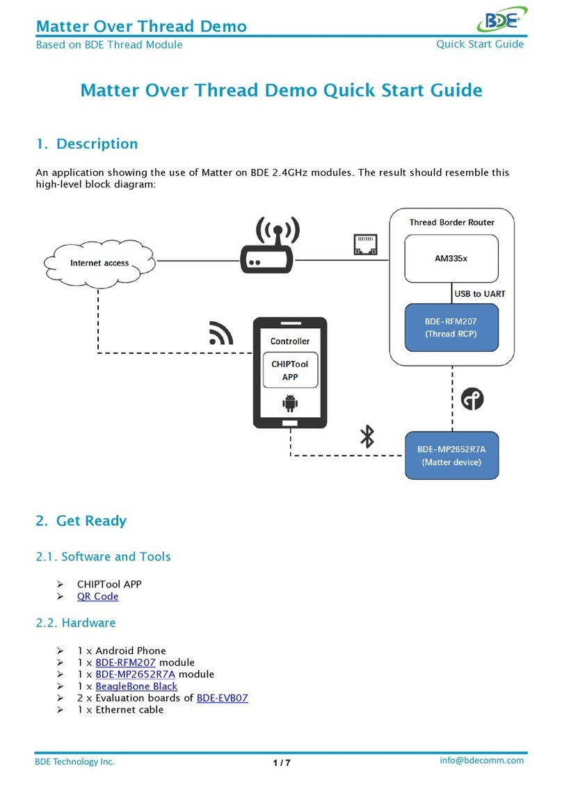
BDE BDM209A User manual

BDE-BDM209A Quick Start
info@bdecomm.com
BDE Technology Inc.
1/ 15
Quick Start Guide - BDE-BDM209A
1. Introduction
This document is a quick start guide for how to develop BDE-BDM209A module with BDE-
EVB07 evaluation board. It provides an instruction of how to modify the Demo source code to
run the Demos on BDE-BDM209A modules.
Figure 1-1: BDE-BDM209A Pinout Diagram Top View
2. BDE-EVB07
BDE-EVB07 is an evaluation board designed for various BDE modules. It is basically the
same as TI launch pad which is used to evaluation TI chips. BDE-EVB07 is made to evaluate
BDE modules.

BDE-BDM209A Quick Start
info@bdecomm.com
BDE Technology Inc.
2/ 15
Figure 2-1: BDE-EVB07 Top View
①Micro USB connector
②Reset button
③P4, Jumpers, to connect or disconnect the module from debug port or UART
④Connect with module
⑤Two LEDs, connect with DIO6 and DIO7
⑥J1, J3, 2.54 mm pins, module pins out
⑦J2, J4, 2.54 mm pins, module pins out
⑧Button 1, connect with DIO13
⑨Button 2, connect with DIO14
⑩XDS110 chip, for programming and debug, also providing USB to UART Converter
3. BDE-ADP-209
BDE-ADP-209 is an adaptor board which connect BDE-BDM209A to the BDE-EVB07.
1
2
3
4
5
6
7
8
9
10

BDE-BDM209A Quick Start
info@bdecomm.com
BDE Technology Inc.
3/ 15
Figure 3-1: BDE-ADP-209 Top View and Bottom View
Figure 3-2: Plug BDE-ADP-209 in BDE-EVB07
IO mapping between BDE-BDM209A and BDE-EVB07:
BDE-BDM209A
BDE-EVB07
TMS
TMS
TCK
TCK
TDO/PJ.5
TDO
TDI/PJ.4
TDI
RST
RST
P1.0
DIO22
P1.1
DIO24
P1.2
RXD, DIO02
P1.3
TXD, DIO03
P1.6
DIO11
P1.7
DIO10

BDE-BDM209A Quick Start
info@bdecomm.com
BDE Technology Inc.
4/ 15
P2.0
DIO15
P2.1
DIO13, Button 1
P2.2
DIO14, Button 2
P2.3
DIO12
P3.0
DIO7, Green LED
P4.0
DIO6, Red LED
P5.6
DIO20
P5.7
DIO19
P6.1
DIO21
AUD_CLK
DIO4
AUD_FSYNC
DIO9
AUD_IN
DIO5
AUD_OUT
DIO8
4. BDE-EVM-209A
BDE-EVM-209A is a breakout board for connecting BDE-BDM209A and BDE-EVB07. Different
from BDE-ADP-209, BDE-EVM-209A integrate stereo audio function which is the same as TI
CC3200AUDBOOST boards.
Figure 4-1: BDE-EVM-209A Top View and Bottom View

BDE-BDM209A Quick Start
info@bdecomm.com
BDE Technology Inc.
5/ 15
Figure 4-2: Plug BDE-EVM-209A in BDE-EVB07
IO mapping between BDE-BDM209A and BDE-EVB07:
BDE-BDM209A
BDE-EVB07
TMS
TMS
TCK
TCK
TDO/PJ.5
TDO
TDI/PJ.4
TDI
RST
RST
P1.0
DIO22
P1.1
DIO24
P1.2
RXD, DIO02
P1.3
TXD, DIO03
P2.0
DIO15
P2.1
DIO13, Button 1
P2.2
DIO14, Button 2
P2.3
DIO12
P3.0
DIO7, Green LED
P4.0
DIO6, Red LED
P5.6
DIO20
P5.7
DIO19
P6.1
DIO21
IO use for stereo audio function:
BDE-BDM209A
TLV320AIC3254
AUD_CLK
MCLK, BCLK
AUD_FSYNC
WCLK
AUD_IN
DOUT
AUD_OUT
DIN
P1.6/SDA
SDA
P1.7/SCL
SCL

BDE-BDM209A Quick Start
info@bdecomm.com
BDE Technology Inc.
6/ 15
5. SDK for BDE-BDM209A
CC2564CMSP432BTBLESW is CC2564C TI Dual-mode Bluetooth Stack on MSP432 MCUs. Stack
download link is:
https://www.ti.com/tool/CC2564CMSP432BTBLESW
Also, developers can find the stack user guide on this page.
Sample applications in the SDK are available for CCS, IAR, and Keil. Developers can follow the
steps in chapter 6.2 of TI stack user guide to set up the sample applications.
CCS link is:
https://www.ti.com/tool/CCSTUDIO-MSP?keyMatch=&tisearch=search-
everything&usecase=partmatches
6. Run the Demos in the CC2564CMSP432BTBLESW SDK on BDE-
BDM209A
To run the sample Demo codes in the CC2564CMSP432BTBLESW SDK on BDE-BDM209A,
please take the following step.
1. Find HRDWCFG.h file, change the I2C pins to P1.6 and P1.7
#define HRDWCFG_I2C_MODULE EUSCI_B0_BASE
#define HRDWCFG_I2C_SDA_PORT_NUM GPIO_PORT_P1
#define HRDWCFG_I2C_SDA_PIN_NUM GPIO_PIN6
#define HRDWCFG_I2C_SCL_PORT_NUM GPIO_PORT_P1

BDE-BDM209A Quick Start
info@bdecomm.com
BDE Technology Inc.
7/ 15
#define HRDWCFG_I2C_SCL_PIN_NUM GPIO_PIN7
7. CC2564x Demo Applications User’s Guide
Developers can get more information about each demo in the SDK from the “CC2564x Demo
Applications User’s Guide” document provided by TI.
The document link is below:
https://www.ti.com/product/CC2564C?keyMatch=CC2564C&tisearch=search-
everything&usecase=GPN#tech-docs
8. Run Bluetooth Stereo Audio Streaming Demo on BDE-BDM209A
8.1 With CC3200AUDBOOST board
If you are using the TI CC3200AUDBOOST board, you need to connect BDE-BDM209A and
CC3200AUDBOOST board first.
Figure 8-1: Connection between BDE-BDM209A and CC3200AUDBOOST

BDE-BDM209A Quick Start
info@bdecomm.com
BDE Technology Inc.
8/ 15
Connection Designator
BDM209A Pin
CC3200AUDBOOST Pin
Ground
GND
J1-4
3V3 Power
VDD
J1-1
AUD_CLK
AUD_CLK
J1-16
AUD_IN
AUD_IN
J1-20
AUD_FSYNC
AUD_FSYNC
J1-14
AUD_OUT
AUD_OUT
J1-18
I2C_SCL
P1.7
J1-17
I2C_SDA
P1.6
J1-19
8.2 With BDE-EVM-209A board
If you are using BDE-EVM-209A, you just need to plug the BDE-EVB-209A in the BDE-EVB07
board.
Before building and burn the audio demo, developers must finish modifying the code refer to
section 6.
Connect the BDE-EVB07 board to a PC using a microUSB cable. It will show up as XDS110 Class
Application/User UART (COM x) for MSP432, under Ports (COM & LPT) in the Device manager.
Figure 8-2: Application UART COM Port
Attach a Terminal program like PuTTY to the serial port x for the board. The serial parameters
to use are 115200 Baud, 8, n, 1.
PuTTY download link:
https://www.chiark.greenend.org.uk/~sgtatham/putty/
Open the PuTTY software, and open a serial terminal as below:

BDE-BDM209A Quick Start
info@bdecomm.com
BDE Technology Inc.
9/ 15
Figure 8-3: PuTTY
A3DP Sink Demo Guide
The Assisted Advanced Audio Distribution Profile (A3DP) Sink allows a device to act as an
Audio sink and can control and stream audio on an Audio source.
Demo project path is:
C:\TI\Connectivity\CC256X BT\CC256x MSP432 Bluetopia SDK\v4.2.1.1\Samples\A3DPDemo_SNK
Connect the BDE-EVB07 to the PC, and use PuTTY to open the UART Port. After the firmware
is flashed into the BDE-BDM209A, reset the module using Reset button and you should see the
stack getting initialized on the PuTTY terminal and the help screen will be displayed, which shows
all of the commands.

BDE-BDM209A Quick Start
info@bdecomm.com
BDE Technology Inc.
10 / 15
Figure 8-4: PuTTY Terminal
Plug your earphone into the Line Out Jack on the BDE-EVM-209A board. A3DP sink demo will
advertise automatic after reset. Use your smartphone to connect and pair with the module in the
Bluetooth settings menu. After the link is established, you should hear the sound via earphone if
the smartphone is playing music.

BDE-BDM209A Quick Start
info@bdecomm.com
BDE Technology Inc.
11 / 15
By default, A3DP sink demo select CODEC_LINE_OUT as output device, as below:

BDE-BDM209A Quick Start
info@bdecomm.com
BDE Technology Inc.
12 / 15
If developers want to use the speaker as the output device. Change the ‘OutputLine’ value, as
below:
But the stack doesn’t implement the speaker initialization code. So, developers should add
the below code in line 391 of CC3200AUDBOOST.c.
case CODEC_SPEAKER:
// Select Page 1
CodecPageSelect(1);
// P1, R14, b3. Left_DAC -> LOL (1)
CodecRegWrite(CODEC_REG_LOL_SEL, 0x08);
// P1, R15, b3. Right_DAC -> LOR (1)
CodecRegWrite(CODEC_REG_LOR_SEL, 0x08);

BDE-BDM209A Quick Start
info@bdecomm.com
BDE Technology Inc.
13 / 15
// P1, R18, b6. LOL Driver = Not Muted (0)
// P1, R18, b5-0. LOL Driver Gain = 0dB
CodecRegWrite(CODEC_REG_LOL_DRV_GAIN, 0x00);
// P1, R19, b6. LOR Driver = Not Muted (0)
// P1, R19, b5-0. LOR Driver Gain = 0dB
CodecRegWrite(CODEC_REG_LOR_DRV_GAIN, 0x00);
// P1, R9, b3. LOL Driver = Power Up (1)
// P1, R9, b2. LOR Driver = Power Up (1)
CodecRegWrite(CODEC_REG_OUT_DRV_CTRL ,0x0C);
// Select Page 0
CodecPageSelect(0);
// P0, R65, b7-0. Left_DAC Volume = 0dB
CodecRegWrite(CODEC_REG_LDAC_VOL, 0x00);
// P0, R66, b7-0. Right_DAC Volume = 0dB
CodecRegWrite(CODEC_REG_RDAC_VOL, 0x00);
// P0, R63, b7. Right_DAC = Power Up (1)
// P0, R63, b6. Right_DAC = Power Up (1)
// P0, R63, b5-4. Left_DAC = Left Channel (01)
// P0, R63, b3-2. Right_DAC = Right Channel (01)
// P0, R63, b1-0. Soft-Stepping = Disabled (10)
CodecRegWrite(CODEC_REG_DAC_CTRL_1, 0xD6);
// P0, R64, b7. Right_DAC_Off = Zero_Data (0)
// P0, R64, b6-4. DAC_Auto_Mute = Disabled (000)
// P0, R64, b3. Left_DAC = Not muted (0)
// P0, R64, b2. Right_DAC = Not muted (0)
// P0, R64, b1-0. DAC_Master_Vol = Independent L/R (00)
CodecRegWrite(CODEC_REG_DAC_CTRL_2, 0x00);
break;
And then , add below code in line 132 of CC3200AUDBOOST.h:
#define CODEC_REG_LOL_SEL 0x0E
#define CODEC_REG_LOR_SEL 0x0F
#define CODEC_REG_LOL_DRV_GAIN 0x12
#define CODEC_REG_LOR_DRV_GAIN 0x13

BDE-BDM209A Quick Start
info@bdecomm.com
BDE Technology Inc.
14 / 15
Developers can select the high gain mode by putting the jumper on as shown in above picture.

BDE-BDM209A Quick Start
info@bdecomm.com
BDE Technology Inc.
15 / 15
More Questions:
Please search existing answers on TI E2E support forums
Contact your local TI sales representative.
Or
Contact BDE Technology, Inc.
USA:
67 E Madison St, #1603A, Chicago, IL 60603
Tel: +1-312-379-9589
Website: http://www.bdecomm.com/ Email: info@bdecomm.com
China:
B2-403, 162 Science Ave, Huangpu District, Guangzhou, 510663
Tel: +86-020-28065335
Website: http://www.bdecomm.com/cn/ Email: [email protected]om
Table of contents
Other BDE Control Unit manuals
Popular Control Unit manuals by other brands
Warren rupp
Warren rupp Sandpiper HDF1 Service & operating manual
Siemens
Siemens SIMATIC 505 Installation and operation guide
JUMO
JUMO mTRON B 70.4015.4 installation instructions
ITRON
ITRON ERT 40W manual
Siemens
Siemens SINAMICS G120D Getting started guide
FASTRON.
FASTRON. OZtherm F-312 Installation and commissioning manual
