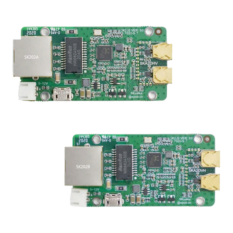
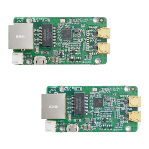
EPS SK202 Series User manual

SK202Specification
GigE
1.Overview
SK202 isapairofRFmod
ule
1GbpsdatarateEthernetto 6
0GH
ofSK202isanRJ45Gigabit
E
SK202modulesarebasedon
l
ea
outputconsist in anRFtransm
centimeter.
2.Features
Ÿ
60GHzV-Band tra
n
Ÿ
GigabitEthernetsh
o
Ÿ
Full duplex,horiz
ont
Ÿ
RJ45MDIinterfa
ce
Ÿ
Used in pairs
3.Application
Ÿ
LEDpanelsform
odul
Ÿ
Video surveillance
c
Ÿ
ContactlessEthern
e
4.Blockdiagram
Board outlook:
1
o
f
SK202
contactlessconnectivity
u
le
swithH&Vhornantenna andG-PHYto
ac
GH
zmillimeterWaveRFsignalconversion.
E
thernetConnectorsupporting 10/100/1000B
a
ea
dingedgeST60A2mmWRFtransceivera
n
m
issionofthecorrespondingSGMIIsignalov
e
n
sceiverwithST60A2
o
rtrangecontactlessconnectivity,preferred
3
n
taltransmissio
n,
ControlledAutonegotia
tion
ace
Ethernetinput
d
ulardisplaywalls
ce c
ame
ra
androbotics
e
tapplicatio
ns
f
3
ac
hieve
Theinput
a
se
-T.
n
dthe
e
rsever
al
3
cm
tion

SK202Specification
5.Assembly
PCBinstallation:
Note:
(1)Ifametalcoverisused,a
w
orothermicrowaveinsens
itiv
(2)TheDCsocketand theUS
B
MICRO-Bsocketisonlyu
bothat thesametime.
(3)It isrecommended that
the in
valueis2 cm, andthemax
i
themaxworkingdistance
6.Characteristics
Recommended operatingcond
Symbol Description
V
IN
Powersupply
C
IN
Inputcurrent(*)
PTotalPowerconsu
m
T
A
AmbientOperating
Temperature,forS
K
T
A
AmbientOperating
Temperature,forS
K
T
J
MaximumJunction
Temperature
T
STG
StorageTemperatu
re
2
o
f
Unit:mm
w
indowshould beaddedformicrowavesign
a
i
tivematerialscanbeusedtofillthewindow
.
B
MICRO-Bsocketare connectedtogether.
T
sedtosupplythepower.Pleasedo notconn
ec
installationdistance
(
A)isat least1cm, th
e
i
mumis5 cm -40~50 High temperatur
e
.
dit
ionsandelectricalcharacteristics
Minimu
mTypical Maxim
um
4.4 12 16
-50 80
m
ption - 0.6 -
K2
02AC/BC 0 - 70
K2
02AI/
BI
-40 - 85
- - 125
re
-40 105
f
3
a
l.
Plastic
T
heUSB
ec
tthem
e
typical
e
willaffect
um
Unit
V
mA
W

SK202Specification 3 of3
Fosc CarrierFrequency 60.3 60.4 60.5 GHz
whenpowersupplyis12VandEthernetisactive.
7.Auto-negotiation
TheEthernetPHYsupports1Gbps,100Mbpsand10Mbpsspeeds.Inorderfor
twoEthernetmodulestocommunicatecorrectly,caremustbetakenthatthePHYon
bothmodulesnegotiatethesamespeed.Theauto-negotiationisalwaysenabledonthe
RealtekPHY.Ittakesplaceindependentlybetweenamoduleandthedevice
connectedonitsRJ45port.Itistheresponsibilityoftheapplicationtoensurethe
auto-negotiationresultisthesameforbothEthernetmodules.
Forexample,ifonemoduleisconnectedtoa100Mbpsmodem,thePC
connectedontheothermoduleshouldbeconfiguredtoguaranteetheauto-negotiation
resultisalso100Mbps.
MoredetailsareavailableintheUserManual.
8.OrderInformation
Part
number Description
SK202A GigEcontactlessmodulewithRealtekRTL8211FS,PortA Originalversion
SK202B GigEcontactlessmodulewithRealtekRTL8211FS,PortB Originalversion
SK202AC GigEcontactlessmodulewithRealtekRTL8211FS,PortA Commercialversion
SK202BC GigEcontactlessmodulewithRealtekRTL8211FS,PortB Commercialversion
SK202AI GigEcontactlessmodulewithRealtekRTL8211FSI,PortA Industrialversion
SK202BI GigEcontactlessmodulewithRealtekRTL8211FSI,PortB Industrialversion
NOTE: PortA: withverticalpolarizedhornantennafortransmittingandhorizontal
polarizedhornantennaforreceiving.
PortB: withhorizontalpolarizedhornantennafortransmittingandvertical
polarizedhornantennaforreceiving.
RevisionHistory
Date Version Changes
OCT282020 2.0 Updateelectricalcharacteristics
NOV112019 1.6 FirstDraft,basedonSK20x_SPEC_1.3version

SK202Usermanual
Thisdocumentguidesus
e
modulestransmitsGigabitE
t
h
contactlessway.SK202open
s
moduleintegratesanetwork
transceiverchip,whichcanb
e
networkcable.Pleasenoteis
t
asdescribed insection3 ofth
i
s
Figure1. Sch
e
SK202 onlyneedsto beco
n
benotedthatthenetwork neg
oti
same.IfthePCsideisagigab
i
SK202Awill be1G.Thenthe
r
willautomaticallynegotiateth
e
be connected,workingonGig
a
Assumingthattherouterhasa
with therouter.Atthistime,t
h
areinconsistent,and thenetw
o
Auto-negotiation below.
Thecategoryofthe cables
u
must be compatiblewith ther
a
notethatSK202AandSK202
B
needstobe alignedwithadis
t
a
1of6
e
rshowtousetheSK202A/Bmodules.
T
th
ernetsignalsatadistanceofseveralcenti
m
anewscenefornetworkconnectionappli
ca
PHYchipandST60A2,amillimeterwa
v
e
simplyconnectedtotheexistingEthernet
r
t
hatbothSK202modulesmustatthesame
s
p
s
documen
t.
e
maticdiagramofusingSK202toconnectIPcamera
on
nectedto thenetworkand powersupply,bu
t
o
tiationrateofthePCsideand theroutersid
e a
i
tnetwork,therateautomaticallyneg
ot
iated
w
r
a
te
ontheroutersidemust be1Gbps, andth
e
e
ratewiththeSK202Bto be 1Gbps.Thene
t
w
a
bitEtherne
t.
rateof100M,SK202Bwill negotiate arate
o
h
erateofSK202Ais1Gbps,and theratesof
S
wo
rkwill not work.Pleaserefertosection C
ont
used to connectthemodulesto therestof
the
a
tethatwillbenegotiated.10/100 or1000M
bp
B
must beused inpairs, and thegoldenanten
n
a
nceofabout3c
m.
T
hepairof
m
etersina
ca
tions.This
v
ewireless
r
eplacinga
p
eedmo
de
t
itshould
e a
rethe
w
iththe
e
router
w
orkwill
o
f100M
S
K202A/B
n
trolled
the
network
b
p
s.
Please
n
apart

SK202Usermanual
Figure2.
P
TheNetworkPHYchipembe
d
isabletosupport10/100/1000
M
communicatetheymustopera
t
connectorofblinkswhena1
G
and thedistantPHY.TheOran
ThePHYsontheSK
2
automaticallywiththedevice
i
placein parallel.
Asaconsequence,ifthe
t
differentmaximumspeeds
, the t
Figure3.
FortheSK202com
mu
advertisingdifferentmaxi
m
fastestdevicehastobecontr
o
2of6
P
hysicalpictureofSK202
non
-contactconnector
d
dedin theSK202isset inAuto-negotiation
m
M
bps.In orderfortheSK202AandSK202B
t
eatthesamespeed.TheGreenLEDon the
R
Gb
pscommunication isestablishedbetween
th
n
geLEDsblinkswhen the communication is
a
K2
02workindependently and eachone
i
tisconnectedto.Sotwoindependentneg
oti
t
wodevices,suchasalaptopandacamer
a,
e
twoauto-negotiationresultswill differ.
Noncontrolledauto-negotiationmayfail
mmun
ication toestablish correctly betwe
e
m
umspeedcapabilities,theauto-negotia
t
i
o
lled.
m
odeand
to
R
J45
h
elocal
a
t10M
bps
negotiates
i
ationstake
a,
advertise
ndevices
i
onofthe

SK202Usermanual
Thankstothecontrolled
a
withtheSK202willbesetu
p
SK202andthecamera.
Figure4. Controlledauto-n
e
Alternatively,onecanintrodu
c
deviceinorderto ensurethe a
u
Figure5.
A
Ifyou need toevaluatethe
recommended to useathird-p
a
3of6
a
uto-negotiationonthelaptop,onecanens
u
p
atthesamespeedthantheonebetween
th
e
gotiationisre
qu
iredwhenthe2devicesdonotadve
r
ti
maximumspeedcapability
c
easwitchoperatingatthesamespeedthan
t
uto
-negotiationresultwillbethesameonb
oth
A
u
to
-negotiationresultcontrolledusingaswitch.
impactofSK202onnetworktransmiss
ion, i
t
a
rtytoolIPERF
3.
Onlyneed twonetworkca
bl
u
rethelink
th
esecond
ti
sethesame
t
heslowest
oth
side
s.
t
is
bl
e an
d two

SK202Usermanual
PCstocompletethetest.You
c
https://iperf.fr/iperf-down
l
o
Iperf3 testmethod:
Figure6.
Refertothefigure6toco
n
needthesamespeed,suchas
G
192.168.10.2,IPaddressof
PC
cablefortesting
PC-Aasaserver,runcom
m
PC-Basclient,runcomm
a
192.168.10.2--time100
IPERF3willtest100sec
on
therewill beBERand jitterre
s
Atserverside:
Atclientside:
Ifyoucareabouttheoutp
ut o
changetheSK202modulesto
thesamecommandforcompa
r
4of6
ca
n downloadfromtheaddressasbel
ow:
wnlo
ad.php
Iperf3testSchematicdiagramwithSK202
on
nect to thenetwor
k.
Thenetworkadapterso
f
G
igabitEthernetcontroller.IPaddressofPC-
A
PC
-Bissetto192.168.10.3.Pleaseuseatleast
C
m
and:
iperf3--server
a
nd:
iperf3--udp --bandwidth1G--c
--len63k
n
dsthroughUDPprotocolwith 1Gbandw
idth
s
ultoutp
ut
astheblowpicture.
put o
fiperf3 test,acomparisontestisnecessar
y
aRJ45connectorto directlyconnecttwoPC
s
r
ison tes
t.
f
twoPCs
A
issetto
C
at
5e-type
lient
h,
and
y
.
Youcan
s
,and use

SK202Usermanual
Figure7.
FortheRFwavestoprop
a
betakennottointroduceany
onthefiguresbelow.ThisKO
A
Thelengthbeing thedistance
b
Moreover,aSafeAreah
a
elementspresentinthisa
r
ea
propagation.
ThisSafeAreaisaparall
e
thedistancebetweentheanten
n
Incaseanelectronicco
m
paintoranysortofreflectiv
analyzed.
Figure8.
Incase ametallic casingis
insertan openingforthemilli
m
5of6
Iperf3testSchematicdiagramwithRJ45cable
a
gatecorrectlyfromonemoduletotheothe
r
,
metallicobstacleinaKeepOutArea(K
OA
A
isaparallelepipedof22mmwidthand9
m
b
etweentheantennae,usually30m
m.
a
sbeendefined,inorangeonthefigures
b
ea
mayhaveanimpactonthemillim
e
e
lepipedof60mmwidthandheight.Thel
e
n
ae,usually20mm.
m
ponent,ametalpart,afastener,ascrew,
s
tiv
esurfaceresidesinthisvolume,itsimpa
c
KeepOutArea(Green)andSafeArea(Orange)
tobeusedaround themodules,itismandato
m
eterwavestopropagate.Thisopeningmay
be
,
caremust
OA
),ingreen
mm
height.
b
elow.The
e
terwaves
e
ngthbeing
omemetal
c
tmustbe
ry
to
be
filled

SK202Usermanual 6 of6
withABSorothermicrowaveinsensitivematerialstomaintainwatertightness.This
openingshouldfollowtheseguidelines:
•
The casingmustbeplacedataround 2.7mmfromthePCBtoensureafree
spaceof0.8mm between theHornantennaebodyand theABShousing.
•
Theopeningshouldbeminimum22mm longand9mmwide,centeredon the2
antennae,butitcan beenlarged.
•
Should the casing beplacedfurtherthan2.7mmfromthe PCB,theopening
dimensionswill havetobe adjusted to preventreflections.
Thisissummarizedinthefigurebelow:
Figure9. Openninginametallichousing
RevisionHistory
Date Version Changes
NOV22020 1.0 InitialRelease
Other manuals for SK202 Series
2
This manual suits for next models
6
Table of contents
Other EPS Control Unit manuals
Popular Control Unit manuals by other brands

Zurn Wilkins
Zurn Wilkins ZW209 Installation, Troubleshooting, Maintenance Instructions

BFT
BFT RIGEL 6 installation manual

Assa Abloy
Assa Abloy TRAKA UD0011 user guide

ICP DAS USA
ICP DAS USA SG-3071 quick start guide

ChemValve-Schmid
ChemValve-Schmid ChemBall CSB Installation & operating instructions

SOMFY
SOMFY Oximo 40 Solar io manual