Boffi FLAT-KAP User manual
-1-
Istruzioni di montaggio
CAPPA IN ACCIAIO INOX - 120 V.
I
Assembly instructions
HOOD IN STAINLESS STEEL - 120 V.
GB
FLAT-KAP
N°MC0243/01
Data: 04.12.2007
ISTRUZIONI DI MONTAGGIO

READ AND SAVE THESE INSTRUCTIONS
INSTALLATION AND USE
IN USA AND CANADA
APPROVED FOR
RESIDENTIAL APPLIANCES
FOR RESIDENTIAL USE ONLY
PLEASE READ ENTIRE INSTRUCTIONS BEFORE PROCEEDING.
INSTALLATION MUST COMPLY WITH ALL LOCAL CODES.
IMPORTANT: Save these Instructions for the Local Electrical Inspectors use.
INSTALLER: Please leave these Instructions with this unit for the owner.
OWNER: Please retain these instructions for future reference.
Safety Warn ng: Turn off power c rcu t at serv ce panel and lock out panel,
before w r ng th s appl ance.
Requ rement: 120 V AC, 60 Hz. 15 or 20 A Branch C rcu t
IMPORTANT SAFETY INSTRUCTIONS
CAUTION: FOR GENERAL VENTILAT-
ING USE ONLY. DO NOT USE TO EX-
HAUST HAZARDOUS OR EXPLOSIVE MA-
TERIALS OR VAPORS.
WARNING - TO REDUCE THE RISK OF
FIRE, ELECTRIC SHOCK, OR INJURY TO
PERSONS, OBSERVE THE FOLLOWING:
A.
Use this unit only in the manner intended by
the manufacturer. If you have questions,
contact the manufacturer.
B.
Before servicing or cleaning the unit, switch
power off at service panel and lock service
panel disconnecting means to prevent power
from being switched on accidentally. When
the service disconnecting means cannot be
locked, securely fasten a prominent warn-
ing device, such as a tag, to the service
panel.
C.
Installation Work and Electrical Wiring
ust Be Done By Qualified Person(s) In
Accordance With All Applicable Codes &
Standards, Including Fire-rated Construc-
tion.
D.
Sufficient air is needed for proper combus-
tion and exhausting of gases through the
flue (chimney) of fuel burning equipment to
prevent back- drafting. Follow the heating
equipment manufacturers guideline and
safety standards such as those published by
the National Fire Protection Association
(NFPA), the American Society for Heating,
Refrigeration and Air Conditioning Engi-
neers (ASHRAE), and the local code au-
thorities.
E.
When cutting or drilling into wall or ceil-
ing, do not damage electrical wiring and
other hidden utilities.
F.
Ducted systems must always be vented to the
outdoors.
CAUTION: To r duc risk of fir and to
prop rly xhaust air, b sur to duct air
outsid - do not v nt xhaust air into
spac s within walls, c ilings, attics, crawl
spac s, or garag s.
WARNING
-
TO REDUCE THE RISK
OF FIRE, USE ONLY METAL DUCT
WORK.
Install this hood in accordance with all
requirements specified.
WARNING - To R duc Th Risk Of Fir
Or El ctric Shock, Do Not Us This Hood
With Any Ext rnal Solid Stat Sp d
Control D vic .
READ AND SAVE THESE INSTRUCTIONS
IMPORTANT SAFETY INSTRUCTIONS
WARNING -
TO REDUCE THE RISK OF A
RANGE TOP GREASE FIRE.
a) Never leave surface units unattended at high
settings. Boilovers cause smoking and
greasy spillovers that may ignite. Heat oils
slowly on low or medium settings.
b ) Always turn hood ON when cooking at high
heat or when flambeing food (i.e. Crepes
Suzette, Cherries Jubilee, Peppercorn Beef
Flambe).
c) Clean ventilating fans frequently. Grease
should not be allowed to accumulate on fan
or filter.
d ) Use proper pan size. Always use cookware
appropriate for the size of the surface ele-
ment.
WARNING - TO REDUCE THE RISK OF
INJURY TO PERSONS, IN THE EVENT
OF A RANGE TOP GREASE FIRE, OB-
SERVE THE FOLLOWING
:
a) S OTHER FLA ES with a close-fitting
lid, cookie sheet, or other metal tray, then
turn off the gas burner or the electric element.
BE CAREFUL TO PREVENT BURNS. If
the flames do not go out immediately,
EVACUATE AND CALL THE FIRE
DEPART ENT.
b ) NEVER PICK UP A FLA ING PAN - you
may be burned.
c ) DO NOT USE WATER, including wet dish-
cloths or towels - a violent steam explosion
will result.
d ) Use an extinguisher
ONLY
if:
1 ) You know you have a class ABC extin-
guisher, and you already know how to op-
erate it.
2 ) The fire is small and contained in the area
where it started.
3 ) The fire department is being called.
4 ) You can fight the fire with your back to
an exit.
READ AND SAVE THESE INSTRUCTIONS
ATTENTION: SEULEMENT POUR
LUTILISATION DAÉRATION. NE PAS
LUTILISER POUR ÉPUISER LA VAPEUR
OU LES MATIÈRES EXPLOSIVES OU
DANGEREUSES.
AVERTISSEMENT - POUR RÉDUIRE LE
RISQUE DINCENDIE, DE CHOC
ÉLECTRIQUE, OU DE LA BLESSURE AUX
PERSONNES, OBSERVER LE SUIVANT:
A. Utiliser cet appareil seulement dans la
manière destinée par le fabricant. Si vous
avez des questions, contacter le fabricant.
B. Avant lentretien ou le nettoyage de
lappareil, couper le courant au tableau de
service, et fermer à clef la moyenne de
débrayage de service pour empêcher
lalimentation dêtre allumée par hasard.
Quand la moyenne de débrayage de service
ne peut pas être fermée à clef, attacher une
étiquette au tableau de service pour indiquer
que l'alimentation a été coupée pour
l'entretien.
C. Le Travail dInstallation et de Câblage
Électrique Doit Être Fait Par les Personne(s)
Qualifiées Conformément à Tous les Codes
& Normes Applicables, y Compris la Con-
struction Calculée à Feu.
D. Lécoulement combur ant pour le
fonctionnement sûr du matériel de la com-
bustion du combustible peut être affecté par
le fonctionnement de cet appareil. Suivre la
directive des fabricants du matériel
chauffant et les normes de sécurité tel que
ceux publiées par lAssociation du Protec-
tion de Feu National (NFPA), et la Société
Américaine pour les Ingénieurs de
Chauffage, de Réfrigération et de
Climatisa- tion (ASHRAE), et les autorités
des codes locales.
LES INSTRUCTIONS DE SÉCURITÉ IMPORTANTES
E. En coupant ou en forant dans un mur ou dans
un plafond, ne pas endommager le câblage
électrique et des autres utilités cachées.
F. Les ventilateurs canalisés doivent être
toujours déchargés à lextérieur.
ATTENTION: Pour réduir l ri s qu
dinc ndi , utilis r s ul m nt l travail du
conduit métalliqu .
Installer ce capot conformé- ment aux toutes
exigences spécifiées par le fabricant de votre
cooktop/cuisinière.
ATTENTION: Pour réduir l risqu
dinc ndi , d choc él ctriqu , n pas utilis r
c tt hott av c aucun dispositif d contrôl
xt ri ur.
ATTENTION:
Pour réduire le risque dincendie,
de choc électrique, installer cette hotte seulement
avec des modeles des moteurs exterieurs indiqués
par le constructeur.

LES INSTRUCTIONS DE SÉCURITÉ IMPORTANTES
AVERTISSEMENT - POUR RÉDUIRE LE
RISQUE DUN FEU DE GRAISSE DU
SOMMET DE LA CUISINIÈRE:
1
. Garder le ventilateur, les filtres et les sur -
faces chargées de la graisse propres.
2
. Toujours mettre le c apot EN ARCHE en
cuisinant à la haute chaleur.
3.
Utiliser les hauts positionnements du
cuisinière sur la cuisinière seulement
quand cest nécessaire. Chauffer lhuile
lentement sur
un positionnement bas à moyen.
4.
Ne pas laisser la cuisinière sans surveillance
pendant la cuisson.
5. Utiliser toujours les batteries de cuisine et
les ustensiles appropriés pour le type et la
quantité de la nourriture ayant préparée.
AVER TISSEMENT: - POUR RÉDUIRE LE
RISQUE DE BLESSURE A UX PERSONNES
DANS LÉVÉNEMENT DUN FEU DE
GRAISSE DU SOMMET DE LA
CUISINIÈRE, OBSER VER LES SUIVANTS:
a) ÉTOUFFER LES FLA ES avec un
couvercle ajusté, une tôle du biscuit ou un
plateau métallique, puis fermer le bec.
SO YEZ CERTAIN DE PÊCHER LES
BRÛLURES. Si les flammes ne
séteindront pas immédiatement,
ÉVA CUER ET APPELER LE SERVICE
DES INCENDIES.
b ) NE J A AIS RA ASSER UNE CASSE-
ROLE EN FLA ES - Vous pouvez être
brûlé.
c ) NE PAS UTILISER DE L EA U, y compris les
torchons mouillés ou les serviettes - une
explosion violente résultera.
d ) Utiliser un extincteur
SEULEMENT
si:
1) Vous savez que vous avez un
e xtincteur de Classe ABC et vous. sa ve z
déjà comment le faire fonctionner.
2) Le feu est petit et est contenu dans
la région où il a commencé.
3) Le service des incendies est appelé.
4) Vous pouvez combattre le feu ave c
votre dos à une sortie.
BEFORE INSTALLING HOOD
1.
For the most efficient air flow exhaust,
use a straight run or as few elbows as
possible.
CAUTION:
Vent unit to outside of
b uilding, only.
2.
Almost two people are necessary for
installation.
3.
The hood is fitted with
Screws and
Drywall Anchors suitable f or most
surfaces, consult a Qualified Installer,
check if they perfectly fit with your
cabinet/wall.
4.
Do not use flex ducting.
5.
COLD W EATHER installations should
have an additional backdraft damper
installed to minimize backward cold air
flow and a nonmetallic thermal break to
minimize conduction of outside tempera-
tures as part of the ductwork. The damper
should be on the cold air side of the
thermal break.
The break should be as close as possible
to where the ducting enters the heated
portion of the house.
6.
ake up air: Local building codes may
require the use of ake-Up Air Systems
when using Ducted Ventilation Systems
greater than specified CF of air move-
ment.
The specified CF varies from locale to
locale. Consult your HVA C professional
for specific requirements in your area.
Electrical requirements
Important: Observe all governing codes and
ordinances.
It is the customers responsibility:
To contact a qualified electrical instal-
ler.
To assure that the electrical installation
is adequate and in conformance with
National Electrical Code, ANSI/NFPA
70 latest edition*, or CSA Standards
C22.1-94, Canadian Electrical Code,
Part 1 and C22.2 No.0- 91 - latest
edition** and all local codes and
ordinances.
If codes permit and a separate ground wire
is used, it is recommended that a qualified
electrician determine that the ground path
is adequate.
Do not ground to a gas pipe.
Check with a qualified electrician if you are
not sure range hood is properly grounded.
Do not have a fuse in the neutral or ground
circuit.
IMPORTANT:
Save Installation Instructions for electrical
inspectors use.
The range hood must be connected with copper
wire only.
The range hood should be connected directly to
the fused disconnect (or circuit breaker) box
through flexible armored or nonmetallic
sheathed copper cable.
Wire sizes must conform to the requirements of
the National Electrical Code ANSI/NFPA 70
latest edition*, or CSA Standards C22.1-94,
Canadian Electrical Code Part 1 and C22.2 No.
0- 91 - latest edition** and all local codes and
ordinances.
A U.L.- or C.S.A.-listed conduit connector must
be provided at each end of the power supply
conduit (at the range hood and at the junction
box).
Copies of the standards listed may be obtained from:
* National Fire Protection Association
Batterymarch Park uincy, Massachusetts 02269
** CSA International 8501 East Pleasant Valley Road
Cleveland, Ohio 44131-5575

B
min. 30"
1
18" 1/16
Y
Z
Y
Z
C
C
Junction
Box
Installation
This hood can be installed on the wall (as a wall
hood) or on the ceiling (as an island hood)
according your needs.
The cooker hood must be placed at a minimum
distance of 30 from the cooking plane for
electric cookers and for gas or mixed cookers.
The hood is equipped with a top air outlet
B
for discharge of fumes to the outside (
Ducting
v rsion
exhaust pipe and pipe fixing clamps
not provided).
Should it not be possible to discharge cooking
fumes and vapour to the outside, the hood can be
used in the
filt r v rsion
, fitting an activated
carbon, fumes and vapours are recycled through
the top of the hood.
Expansion wall plugs are provided to secure the
hood to most types of walls/ceilings. However,
a qualified technician must verify suitability of
the materials in accordance with the type of wall/
ceiling. The wall/ceiling must be strong enough
to take the weight of the hood.
Pr liminary information for installation of
th hood:
Disconnect the hood during electrical
connection, by turning the home mains switch
off.
Remove the vapour screens and the grease filter.
Do not tile, grout or silicone this appliance to the
wall. Surface mounting only.
Do not fix chimney flue to furniture or fly over
shelves unless the chimney flue can be easily
removed, in case maintenance is ever required.
Installing th hood on th wall
1.
Using a pencil, draw a line on the wall,
extending up to the ceiling, to mark the
centre. This will facilitate installation.
Draw two horizontal line: the first UST
correspond to the lower side of the hood the
second at 18 1/16 over the first.
This last corresponds to the location of the
upper hood support fixing holes.
2.
Rest the hood support bracket on the wall so
that its center coincides with the center ver-
tical line, and through the upper holes the
upper horizontal line is visible, mark the four
outer holes and drill them, insert 4 wall plugs
and fix the hood support bracket into place
using four screws.
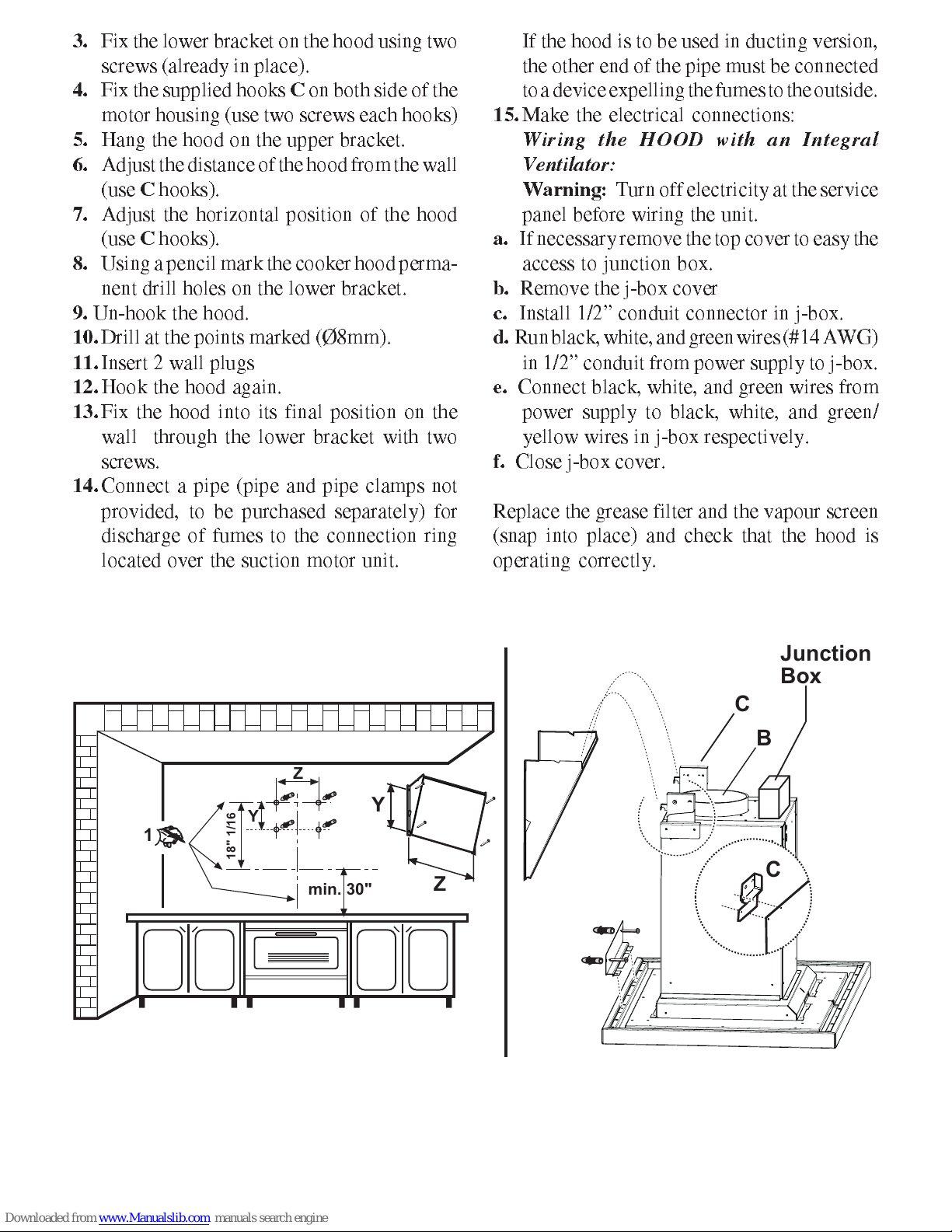
3.
Fix the lower bracket on the hood using two
screws (already in place).
4.
Fix the supplied hooks
C
on both side of the
motor housing (use two screws each hooks)
5.
Hang the hood on the upper bracket.
6.
Adjust the distance of the hood from the wall
(use
C
hooks).
7.
Adjust the horizontal position of the hood
(use
C
hooks).
8.
Using a pencil mark the cooker hood perma-
nent drill holes on the lower bracket.
9.
Un-hook the hood.
10.
Drill at the points marked (Ø8mm).
11.
Insert 2 wall plugs
12.
Hook the hood again.
13.
Fix the hood into its final position on the
wall through the lower bracket with two
screws.
14.
Connect a pipe (pipe and pipe clamps not
provided, to be purchased separately) for
discharge of fumes to the connection ring
located over the suction motor unit.
If the hood is to be used in ducting version,
the other end of the pipe must be connected
to a device expelling the fumes to the outside.
15.
ake the electrical connections:
Wiring the HOOD with an Integral
Ventilator:
Warning:
Turn off electricity at the service
panel before wiring the unit.
a.
If necessary remove the top cover to easy the
access to junction box.
b.
Remove the j-box cover
c.
Install 1/2 conduit connector in j-box.
d.
Run black, white, and green wires (#14 AWG)
in 1/2 conduit from power supply to j-box.
.
Connect black, white, and green wires from
power supply to black, white, and green/
yellow wires in j-box respectively.
f.
Close j-box cover.
Replace the grease filter and the vapour screen
(snap into place) and check that the hood is
operating correctly.
B
min. 30"
1
18" 1/16
Y
Z
Y
Z
C
C
Junction
Box

Description of the hood
1
Control panel
2
Grease filter
3
lamps
4
Vapour screens
5
Outlet hole
Operation
The hood is fitted with one motor having
several speed. Turn the hood on a few minu-
tes before you start cooking, you will then
get an under pressure in the kitchen. The
hood should be left on after cooking for
about 15 minutes or until all the odours have
disappeared.
The control switches are located on the units
front panel:
The hood operation may be controlled via
the control ball or with the remote control
(the remote control is a special accessory and
is ordered separately).
Every status change (changing speed,
switching on the lights, etc.) and is
recognizable from the variation of light
emitted by the control ball and by an acoustic
signal.
The control ball serves also as a light signal :
No signal :
The hood is switched off.
Static gr n light :
Hood is switched on at power level 1 (mini-
mum).
Static orang light :
Hood is switched on at power level 2 (me-
dium).
Static r d light :
Hood is switched on at power level 3 (maxi-
mum).
Alt rnating r d light :
Hood is switched on at intensive power level
(timed at 5 minutes)
Alt rnating gr n light :
Indicates the grease filter saturation - clean
the grease filter
Alt rnating orang light :
Indicates the charcoal filter saturation -
clean or replace the charcoal filter
Attention!
The control Ball flashes orange to indicate
the saturation of the odor filter even when the
charcoal filter is not installed inside the
cooker hood.
However perform the signal reset operation
as follows: select the intensive speed (the
control ball lights up with a red flashing
light), depress again and hold depressed for
about 3 seconds until a bip sound indicates
the reset.
1
2
3
3
4
5

Switching on the hood
The control ball is a balancer switch.
Depressing the control ball repeatedly towards
the right switches on the hood and you may
select the suction level desired, depressing once
again on the right the hood switches off.
Switching on the light
Depress the control ball towards the left :
once for submersed lighting,
once again for full lighting,
depress again to switch off the light.
Control device for grease
or charcoal filter
The air duct, in this hood, is provided with a
device that signals when the filter requires
cleaning or changing .
L d signal for gr as filt r
The LED signal flickers (flickering green light)
when the grease filter requires cleaning, occurs
at about 40 operating hours.
Carefully note the device for grease filter main-
tenance!
L d signal for charcoal filt r
The LED signal flickers (flickering orange light)
when the charcoal filter requires cleaning or
replacing, occurs at about 160 operating hours.
Carefully note the device for charcoal filter
maintenance!
R s tting th saturation indicator
After cleaning or replacing the filter, select the
intensive speed (the control ball lights up with
a red flashing light), depress again and hold
depressed for about 3 seconds until a bip sound
indicates the reset.
depress towards
the right to switch
on the hood
depress towards
the left to switch
on the light.
Maintenance
Prior to any maintenance operation ensure that
the cooker hood is disconnected from the power
supply.
Cl aning:
The cooker hood should be cleaned
regularly internally and externally.
For cleaning use a cloth moistened with
denatured alcohol or neutral liquid detergents.
Avoid abrasive detergents.
Warning:
Failure to carry out the basic stan-
dards of the cleaning of the cooker hood and
replacement of the filters may cause fire risks.
Therefore we recommend observing these ins-
tructions.
Gr as filt r
This must be cleaned once a month using non
aggressive detergents, either by hand or in the
dishwasher, which must be set to a low
temperature and a short cycle. When washed in
a dishwasher, the grease filter may discolour
slightly, but this does not affect its filtering
capacity. To remove the grease filter, pull the
spring release handle.
a
b
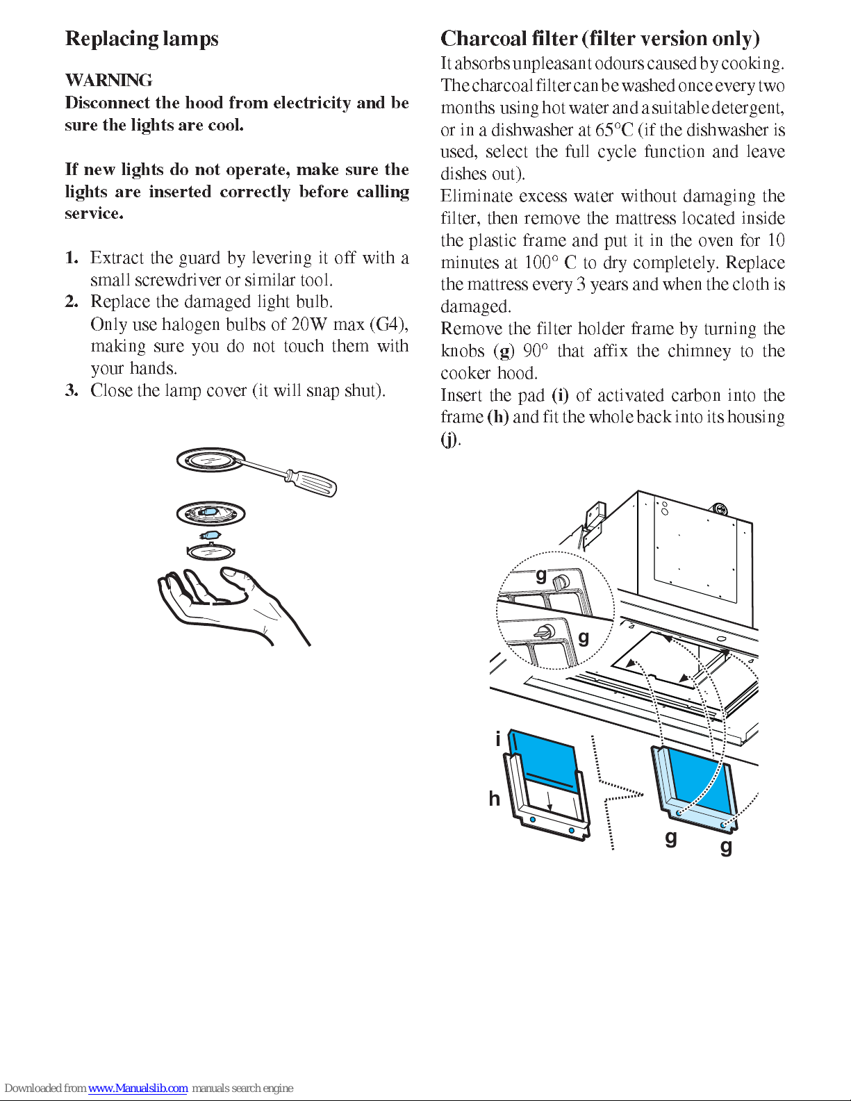
Replacing lamps
WARNING
Disconn ct th hood from l ctricity and b
sur th lights ar cool.
If n w lights do not op rat , mak sur th
lights ar ins rt d corr ctly b for calling
s rvic .
1.
Extract the guard by levering it off with a
small screwdriver or similar tool.
2.
Replace the damaged light bulb.
Only use halogen bulbs of 20W max (G4),
making sure you do not touch them with
your hands.
3.
Close the lamp cover (it will snap shut).
Charcoal filter (filter version only)
It absorbs unpleasant odours caused by cooking.
The charcoal filter can be washed once every two
months using hot water and a suitable detergent,
or in a dishwasher at 65°C (if the dishwasher is
used, select the full cycle function and leave
dishes out).
Eliminate excess water without damaging the
filter, then remove the mattress located inside
the plastic frame and put it in the oven for 10
minutes at 100° C to dry completely. Replace
the mattress every 3 years and when the cloth is
damaged.
Remove the filter holder frame by turning the
knobs (
g
) 90° that affix the chimney to the
cooker hood.
Insert the pad
(i)
of activated carbon into the
frame
(h)
and fit the whole back into its housing
(j)
.
g
g
g
g
h
i
Caution
This appliance is designed to be operated by
adults. Children should not be allowed to tamper
with the controls or play with the appliance. Do
not use the cooker hood where the grill is not
correctly fixed! The suctioned air must not be
conveyed in the same channel used for fumes
discharged by appliances powered by other than
electricity. The environment must always be
adequately aerated when the cooker hood and
other appliances powered by other than
electricity are used at the same time. Flambé
cooking with a cooker hood is prohibited. The
use of a free flame is damaging to the filters and
may cause fire accidents, therefore free flame
cooking must be avoided. Frying of foods must
be kept under close control in order to avoid
overheated oil catching fire. Carry out fumes
discharging in accordance with the regulations
in force by local laws for safety and technical
restrictions.
All r sponsibility, for any v ntual
inconv ni nc s, damag s or fir s caus d by
not complying with th instructions in this
manual, is d clin d.
mit Abluft- und Umluftsystem
mit Abluft- und Umluftsystem
CAPPA
HOOD
HOTTE
CAPPA
HOOD
HOTTE
Mod.
FLAT KAP
Mod.
FLAT KAP
aspirante / depurante
outdoor venting / air recirculation
évacuation extérieure / recyclage
aspirante / depurante
outdoor venting / air recirculation
évacuation extérieure / recyclage
DUNSTABZUGSHAUBE
DUNSTABZUGSHAUBE
Istruzioni per l'uso e l'installazione
Instructions for use and installation
Mode d'emploi et installation
Gebrauchsanweisungen
Istruzioni per l'uso e l'installazione
Instructions for use and installation
Mode d'emploi et installation
Gebrauchsanweisungen


IT
Istruzioniperl’installazione
Sommario
Installazione modello Isola, 1-5
Predisposizione faretti 6
Installazione modello Parete, 7-10
CAPPA FLAT KAP
Italiano, 1 Français, 21
Deutsch, 31
English, 11
GB
IT
FR
DE
2
IT
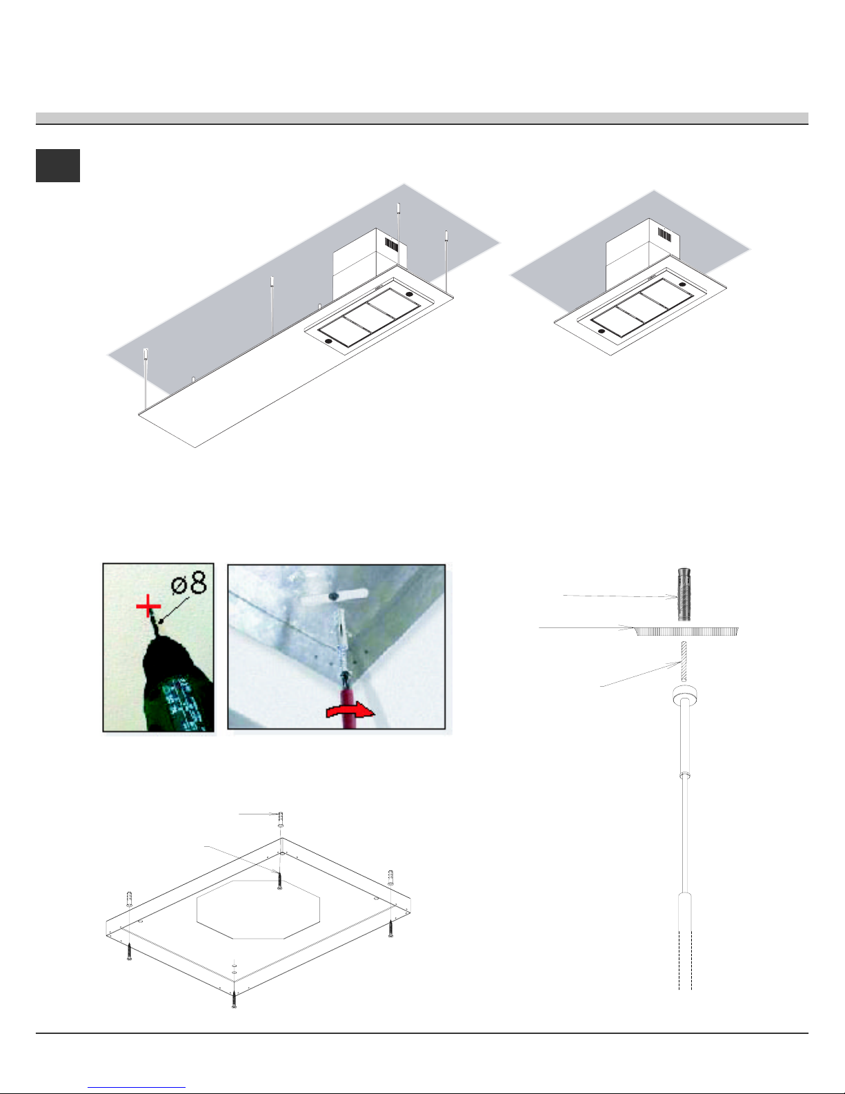
Installazione modello ad isola
L>120 cm
L=90 -120 cm
Esempio installazione Flat Kap con lunghezza
superiore a 120cm Esempio installazione Flat Kap con
lunghezza di 90 - 120cm
Posizionare la vela dove è prevista l’installazione, posizionare il piatto-muro all’interno del foro cappa nella vela,
riportare sul soffitto le posizioni dei fori, e dove presenti, riportare anche le posizioni dei tiranti, quindi forare e fissare
con tasselli/viti in dotazione
Vite
Tassello
Tassello
Barra filettata
Muro

3
IT
Fissaggio angolari camino a piatto-muro sul con viti in dotazione
Fissaggio angolari camino a supporto gruppo aspirante Flat Kap
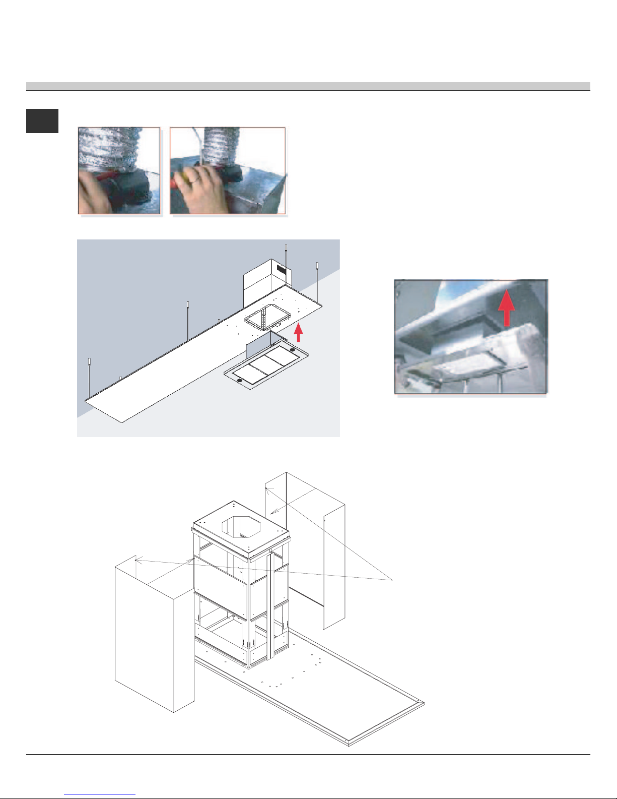
4
IT
Fissaggio corpo aspirante
Fissaggio tubo camino
Fissaggio carter camino
Fissare estremità con viti
Other manuals for FLAT-KAP
1
Table of contents
Languages:
Other Boffi Ventilation Hood manuals

Popular Ventilation Hood manuals by other brands


FULGOR
FULGOR FTHD 900 TC X Instructions for installation and use

AEG
AEG 1400 D Operating and installation instructions

Smeg
Smeg PASC7801FPX Installation and operating instructions

Greenheck
Greenheck Vektor-MH Installation, operation and maintenance manual

Hotpoint Ariston
Hotpoint Ariston HLB 9.5S AT/HA operating instructions

Hauslane
Hauslane chef Series user manual


