Boffi FLAT-KAP User manual
-1-
Istruzioni di montaggio
CAPPA IN ACCIAIO INOX - 220 V.
I
Assembly instructions
HOOD IN STAINLESS STEEL - 220 V.
GB
FLAT-KAP
N°MC0242/01
Data: 04.12.2007
ISTRUZIONI DI MONTAGGIO

GB INSTRUCTION ON MOUNTING AND USE
I ISTRUZIONI DI MONTAGGIO E DUSO
Installation
This hood can be installed on the wall (as a wall hood) or
on the ceiling (as an island hood) according your needs.
The cooker hood must be placed at a minimum distance of
75 cm from the cooking plane for electric cookers and for gas
or mixed cookers.
If the instructions for installation for the gas hob specify a
greater distance, this must be adhered to.
The hood is equipped with a top air outlet B for discharge
of fumes to the outside (Ducting version exhaust pipe
and pipe fixing clamps not pro ided).
Should it not be possible to discharge cooking fumes and
apour to the outside, the hood can be used in the filter
version, fitting an acti ated carbon, fumes and apours are
recycled through the top of the hood.
Expansion wall plugs are pro ided to secure the hood to
most types of walls/ceilings. Howe er, a qualified technician
must erify suitability of the materials in accordance with the
type of wall/ceiling. The wall/ceiling must be strong enough
to take the weight of the hood.
Preliminary information for installation of the hood:
Disconnect the hood during electrical connection, by turning
the home mains switch off.
Remo e the apour screens and the grease filter.
Do not tile, grout or silicone this appliance to the wall. Surface
mounting only.
Do not fix chimney flue to furniture or fly o er shel es unless
the chimney flue can be easily remo ed, in case maintenance
is e er required.
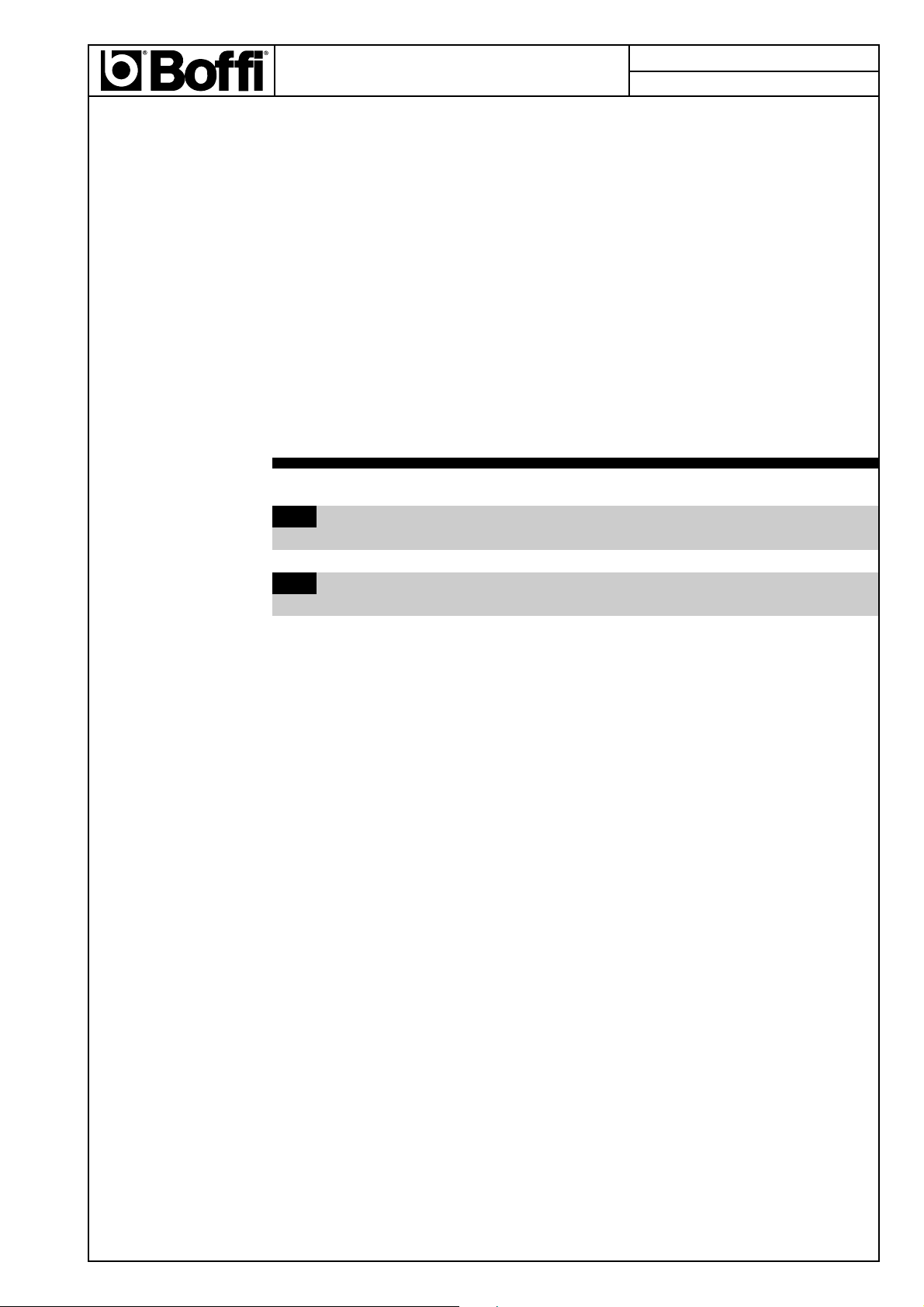
Installing the hood on the wall
1. Using a pencil, draw a line on the wall, extending up to
the ceiling, to mark the centre. This will facilitate
installation.
Draw two horizontal line: the first MUST correspond to
the lower side of the hood the second at 458mm o er
the first.
This last corresponds to the location of the upper hood
support fixing holes.
2. Rest the hood support bracket on the wall so that its center
coincides with the center ertical line, and through the
upper holes the upper horizontal line is isible, mark the
four outer holes and drill them, insert 4 wall plugs and
fix the hood support bracket into place using four screws.
3. Fix the lower bracket on the hood using two screws
(already in place).
. Fix the supplied hooks C on both side of the motor
housing (use two screws each hooks)
5. Hang the hood on the upper bracket.
6. Adjust the distance of the hood from the wall (use C
hooks).
7. Adjust the horizontal position of the hood (use C hooks).
8. Using a pencil mark the cooker hood permanent drill
holes on the lower bracket.
9. Un-hook the hood.
10. Drill at the points marked (Ø8mm).
11. Insert 2 wall plugs
12. Hook the hood again.
13. Fix the hood into its final position on the wall through the
lower bracket with two screws.
1 . Make all connections.
Replace the grease filter and the apour screen (snap into
place) and check that the hood is operating correctly.
Electrical connection
The electrical tension must correspond to the tension noted
on the label placed inside the cooker hood. Connect the
electrical plug, where pro ided, to the an easily accessible
outlet in conformity with local standards in force.
Where an electrical plug is not pro ided (for direct connection
to electrical network) place a standards appro ed bipolar
switch with an aperture distance of not less than 3mm
(accessible) from the contacts.
B
min. 50 cm
min. 75 cm
1458
mm
Y
Z
Y
Z
C
C

3
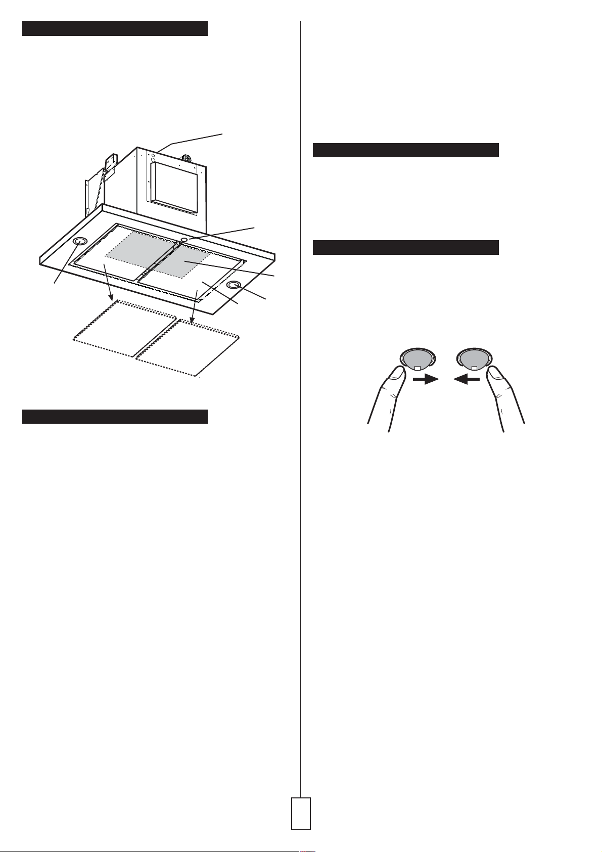
Description of the hood
1 Control panel
2 Grease filter
3 lamps
4 Vapour screens
5 Outlet hole
1
2
3
3
4
5
Operation
The hood is fitted with one motor ha ing se eral speed.
Turn the hood on a few minutes before you start cooking,
you will then get an under pressure in the kitchen. The
hood should be left on after cooking for about 15 minutes
or until all the odours ha e disappeared.
The control switches are located on the units front panel:
The hood operation may be controlled ia the control ball
or with the remote control (the remote control is a special
accessory and is ordered separately).
E ery status change (changing speed, switching on the
lights, etc.) and is recognizable from the ariation of light
emitted by the control ball and by an acoustic signal.
The control ball ser es also as a light signal :
No signal :
The hood is switched off.
Static green light :
Hood is switched on at power le el 1 (minimum).
Static orange light :
Hood is switched on at power le el 2 (medium).
Static red light :
Hood is switched on at power le el 3 (maximum).
Alternating red light :
Hood is switched on at intensi e power le el (timed at
5 minutes)
Alternating green light :
Indicates the grease filter saturation - clean the grease
filter
Alternating orange light :
Indicates the charcoal filter saturation - clean or replace
the charcoal filter
Attention!
The control Ball flashes orange to indicate the saturation
of the odor filter e en when the charcoal filter is not
installed inside the cooker hood.
Howe er perform the signal reset operation as follows:
select the intensi e speed (the control ball lights up with
a red flashing light), depress again and hold depressed
for about 3 seconds until a bip sound indicates the reset.
Switching on the hood
The control ball is a balancer switch.
Depressing the control ball repeatedly towards the right
switches on the hood and you may select the suction le el
desired, depressing once again on the right the hood
switches off.
Switching on the light
Depress the control ball towards the left :
once for submersed lighting,
once again for full lighting,
depress again to switch off the light.
Control device for grease
or charcoal filter
The air duct, in this hood, is pro ided with a de ice that
signals when the filter requires cleaning or changing .
Led signal for grease filter
The LED signal flickers (flickering green light) when the
grease filter requires cleaning, occurs at about 40 operating
hours.
Carefully note the de ice for grease filter maintenance!
Led signal for charcoal filter
The LED signal flickers (flickering orange light) when the
charcoal filter requires cleaning or replacing, occurs at about
160 operating hours.
Carefully note the de ice for charcoal filter maintenance!
Resetting the saturation indicator
After cleaning or replacing the filter, select the intensi e
speed (the control ball lights up with a red flashing light),
depress again and hold depressed for about 3 seconds until
a bip sound indicates the reset.
depress towards the
right to switch on the
hood
depress towards
the left to switch on
the light.
4
Using the Remote Control
The remote control may operate in humid en ironments, but
not when placed on wet surfaces.
Selecting the Suction Speed position the remote control
ertically near the cook top area and rotate clockwise to
increase the suction speed, and anticlockwise to decrease
the suction speed.
Turning on the Light, press the remote control from the
top downwards once for suffused lighting, again for full
lighting, and again to turn off the light.
Remote Control Maintenance
Clean the remote control using non abrasi e detergents.
Follow the instructions below in order to replace the batteries
for the remote control :
- Using a small screwdri er, raise the co er on the base
of the remote control, in order to access the battery
compartment.
Remo e the battery holder, and replace 4 new batteries
type ..394 of 1.5V.
- Place the batteries in order in the battery holder (see Fig.
5) taking care to respect the polarities indicated on the
base of the upper section of the remote control.
Warning!
If the remote control doesnt work after installation (yet the
control ball works correctly), do the following:
1. Place the remote control on the work surface near the
hood.
2. Disconnect the hood from the mains.
3. Reconnect the hood to the mains.
Follow this procedure whene er the remote control
doesnt work for no apparent reason (e.g.: dead battery).
5
Maintenance
Prior to any maintenance operation ensure that the cooker
hood is disconnected from the power supply.
Cleaning: The cooker hood should be cleaned regularly
internally and externally.
For cleaning use a cloth moistened with denatured alcohol
or neutral liquid detergents. A oid abrasi e detergents.
Warning: Failure to carry out the basic standards of the
cleaning of the cooker hood and replacement of the filters
may cause fire risks.
Therefore we recommend obser ing these instructions.
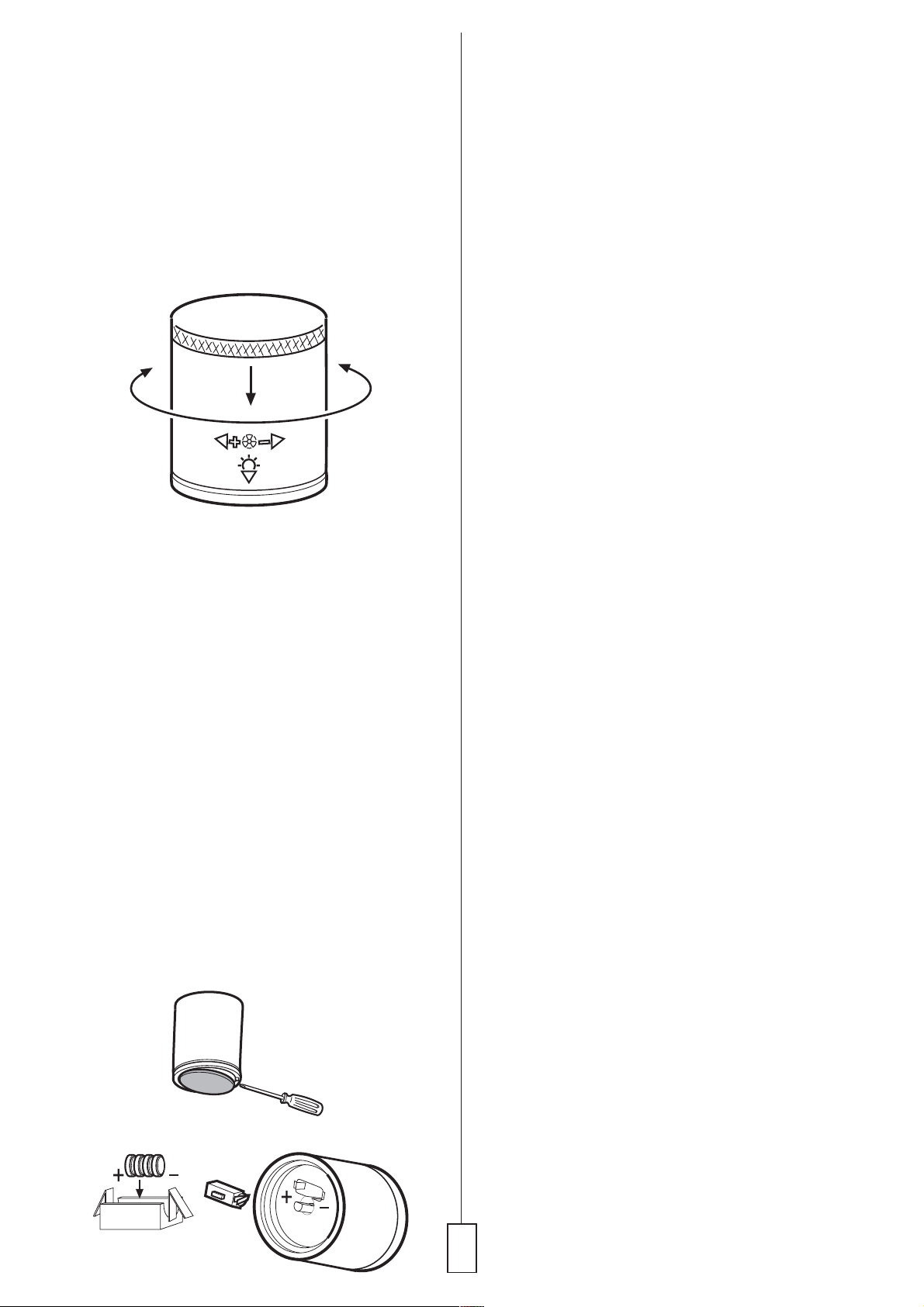
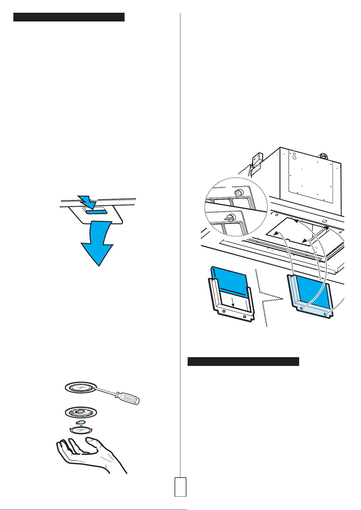
Grease filter
This must be cleaned once a month using non aggressi e
detergents, either by hand or in the dishwasher, which must
be set to a low temperature and a short cycle. When washed
in a dishwasher, the grease filter may discolour slightly, but
this does not affect its filtering capacity. To remo e the
grease filter, pull the spring release handle.
a
b
Replacing lamps
Warning! Prior to touching the light bulbs ensure they are
cooled down.
1. Extract the guard by le ering it off with a small screwdri er
or similar tool.
2. Replace the damaged light bulb.
Only use halogen bulbs of 20W max (G4), making sure
you do not touch them with your hands.
3. Close the lamp co er (it will snap shut).
If the lights do not work, make sure that the lamps are
fitted properly into their housings before you call for
technical assistance.
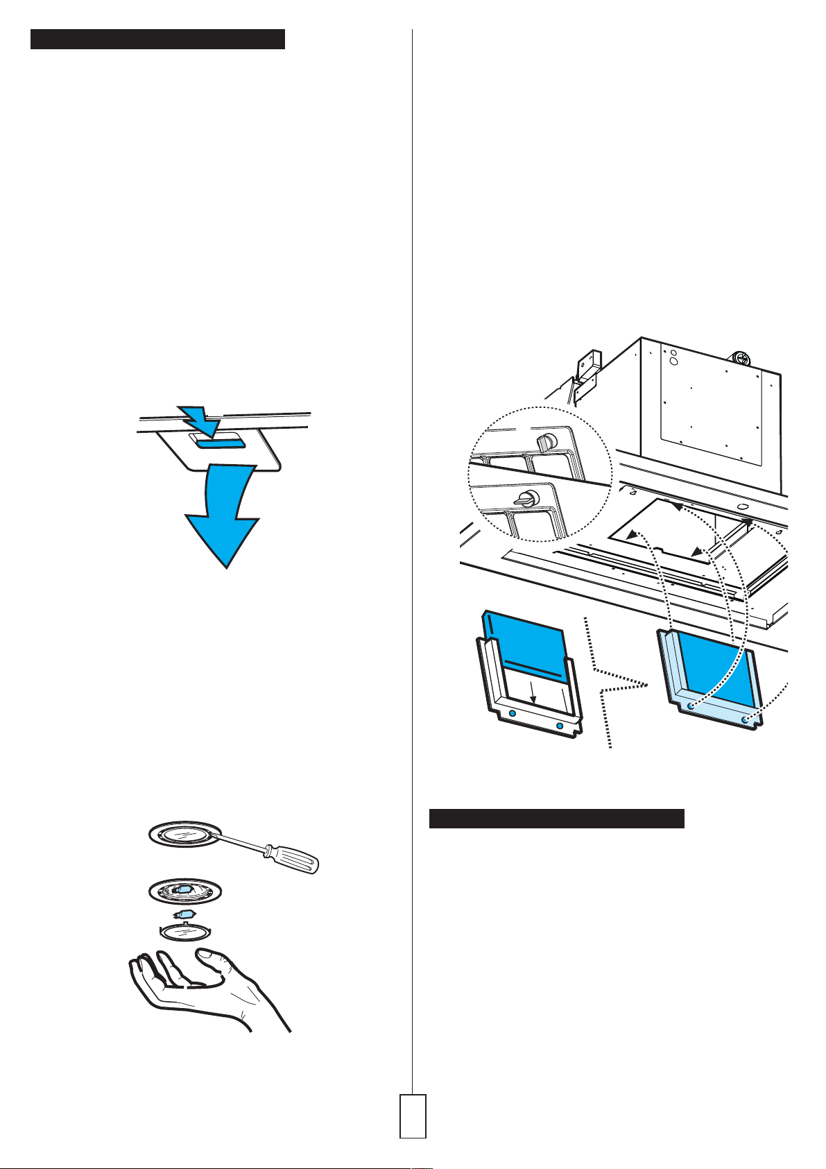
Charcoal filter (filter version only)
It absorbs unpleasant odours caused by cooking.
The charcoal filter can be washed once e ery two months
using hot water and a suitable detergent, or in a dishwasher
at 65°C (if the dishwasher is used, select the full cycle
function and lea e dishes out).
Eliminate excess water without damaging the filter, then
remo e the mattress located inside the plastic frame and put
it in the o en for 10 minutes at 100° C to dry completely.
Replace the mattress e ery 3 years and when the cloth is
damaged.
Remo e the filter holder frame by turning the knobs (g) 90°
that affix the chimney to the cooker hood.
Insert the pad (i) of acti ated carbon into the frame (h) and
fit the whole back into its housing (j).
g
g
g
g
h
i
Caution
This appliance is designed to be operated by adults. Children
should not be allowed to tamper with the controls or play with
the appliance. Do not use the cooker hood where the grill is
not correctly fixed! The suctioned air must not be con eyed
in the same channel used for fumes discharged by appliances
powered by other than electricity. The en ironment must
always be adequately aerated when the cooker hood and
other appliances powered by other than electricity are used
at the same time. Flambé cooking with a cooker hood is
prohibited. The use of a free flame is damaging to the filters
and may cause fire accidents, therefore free flame cooking
must be a oided. Frying of foods must be kept under close
control in order to a oid o erheated oil catching fire. Carry
out fumes discharging in accordance with the regulations in
force by local laws for safety and technical restrictions.
All responsibility, for any eventual inconveniences,
damages or fires caused by not complying with the
instructions in this manual, is declined.

Installazione
Questa cappa può essere appesa al muro o installata sul
soffitto in base alla Vs. necessità..
La cappa de e a ere una distanza minima dal piano cottura
di 75 cm in caso di cucine elettriche e in caso di cucine a
gas o miste.
Se le istruzioni di installazione del dispositi o di cottura a gas
specificano una distanza maggiore, bisogna tenerne conto.
La cappa è fornita di una uscita daria superiore B per lo
scarico dei fumi erso l'esterno (Versione aspirante- tubo
di scarico e fascette di fissaggio non fornite).
Nel caso non sia possibile scaricare i fumi e apori della
cottura erso lesterno, si può utilizzare la cappa in versione
filtrante montando un filtro ai carboni atti i, i fumi e apori
engono riciclati attra erso la parte superiore della cappa.
La cappa è dotata di tasselli di fissaggio adatti alla maggior
parte di pareti/soffitti. E tutta ia necessario interpellare un
tecnico qualificato per accertarVi sullidoneità dei materiali a
seconda del tipo di parete/soffitto. Il parete/soffitto de e
essere sufficientemente robusto da sostenere il peso della
cappa.
Informazioni preliminari per linstallazione della
cappa:
Scollegare la cappa agendo sul quadro generale domestico
nelle fasi del collegamento elettrico.
Rimuo ere gli schermi del apore e il filtro grassi.
Installazione della cappa al muro
1. Con una matita, eseguire una linea sulla parete, sino al
soffitto, corrispondente alla linea di mezzeria, faciliterà
le operazioni di installazione.
Eseguire due linee orizzontali, la prima in corrispondenza
del bordo inferiore della cappa, la seconda a 458 mm
dalla prima, questultima corrisponde ai fori superiori
della staffa di aggancio della cappa.
2. Appoggiare la staffa al muro in modo che il centro
corrisponda con la linea erticale di mezzeria, e attra erso
i fori superiori sia isibile la linea orizzontale superiore,
segnare i 4 fori esterni, forare ed inserire 4 tasselli a muro
e fissare la staffa con 4 iti.
3. Fissare la staffa inferiore alla cappa con 2 iti ( iti già in
posizione).
. Fissare gli agganci C su entrambi i lati del cassone del
motore (usare due iti ogni gancio).
5. Appendere la cappa alla staffa superiore.
6. Regolare la distanza della cappa dalla parete (usare gli
agganci C).
7. Regolare lassetto orizzontale della cappa (usare gli
agganci C).
8. Segnare con una matita i fori per il fissaggio definiti o
della cappa al muro.
9. Togliere la cappa dalla staffa.
10. Forare nei punti marcati.
11. Inserire 2 tasselli.
12. Riagganciare la cappa.
13. Fissare definiti amente la cappa al muro attra erso la
staffa inferiore con 2 iti.
1 . Eseguire tutte le connessioni
Rimontare il filtro grassi e gli schermi apori (fissaggio a
scatto) controllare il perfetto funzionamento della cappa.
Collegamento elettrico
La tensione di rete de e corrispondere alla tensione riportata
sulletichetta caratteristiche situate allinterno della cappa. Se
pro isto di spina allacciare la cappa ad una presa conforme
alle norme igenti posta in zona accessibile. Se spro isto
di spina (collegamento diretto alla rete) applicare un interruttore
bipolare a norme con una distanza dei contatti in apertura non
inferiore a 3mm (accessibile).
B
min. 50 cm
min. 75 cm
1458
mm
Y
Z
Y
Z
C
C
7
Descrizione della cappa
1Pannello di controllo
2Filtro antigrasso
3Lampade
Schermo apori
5Uscita aria
1
2
3
3
4
5
Funzionamento della cappa
La cappa è dotata di un motore con elocità regolabile.
Si consiglia di atti are la cappa alcuni minuti prima di
iniziare la cottura e farla funzionare altri 15 minuti circa
al termine della cottura, allo scopo di eliminare con
sicurezza tutti gli odori.
Il funzionamento della cappa può essere controllato con
la "control ball" o tramite il telecomando.
Ogni cambiamento di stato (cambio elocità, accensione
luci etc.) è riconoscibile dalla ariazione di luce emessa
dalla control ball e da un segnale sonoro.
La control ball serve anche da segnalatore luminoso:
Nessuna segnalazione:
La cappa è spenta.
Luce verde fissa:
Cappa accesa a potenza 1 (minima).
Luce arancio fissa:
Cappa accesa a potenza 2 (media).
Luce rossa fissa:
Cappa accesa a potenza 3 (massima).
Luce rossa lampeggiante:
Cappa accesa a potenza intensi a (temporizzata a 5
minuti)
Luce verde lampeggiante:
Indica la saturazione del filtro grassi - eseguire la pulizia
del filtro grassi
Luce arancio lampeggiante:
Indica la saturazione del filtro al carbone atti o - eseguire
la pulizia o sostituzione del filtro al carbone atti o.
Attenzione!
La control Ball lampeggia in arancio per indicare la saturazione
del filtro al carbone atti o anche quando non è installato
allinterno della cappa.
Eseguire comunque le operazioni di reset della segnalazione.
Procedere come segue: selezionare la elocità intensi a (la
control ball si accende con luce rossa lampeggiante),
premere ancora mantenendo premuto per circa 3 secondi
sino ad udire un segnale sonoro (bip) che indica l'a enuto
reset.
Per accendere la cappa
La control ball è un interruttore a bilanciere.
Premendo la control ball erso destra ripetutamente si
accende la cappa e si seleziona la potenza di aspirazione
sino allintensi o, premendo ancora a destra la cappa si
spegne.
Per accendere la luce
Premere la control ball erso sinistra: una olta per a ere
luce soffusa,
premere ancora per a ere luce piena, premere ancora per
spengere la luce.
Dispositivo di controllo del filtro
La cappa è fornita di un dispositi o che segnala quando il
filtro de e essere pulito o sostituito.
Spia di segnalazione della saturazione del filtro
grassi
La spia lampeggia (luce erde lampeggiante) quando il filtro
grassi de e essere pulito, questo succede ogni 40 ore di
funzionamento.
Seguire con cura tutte le istruzioni relati e alla manutenzione
del filtro grassi.
Spia di segnalazione della saturazione del filtro al
carbone attivo
La spia lampeggia (luce arancio lampeggiante) quando il filtro
al carbone atti o de e essere pulito o sostituito, questo
succede ogni 160 ore di funzionamento. Seguire con cura
tutte le istruzioni relati e alla manutenzione del filtro al
carbone atti o.
Reset della segnalazione di saturazione filtri
Dopo a er pulito o sostituito i filtri , selezionare la elocità
intensi a (la control ball si accende con luce rossa
lampeggiante), premere ancora mantenendo premuto per
circa 3 secondi sino ad udire un segnale sonoro (bip) che
indica l'a enuto reset.
Premere erso destra
per accendere
la cappa.
Premere erso
sinistra per
accendere la luce.

8
Utilizzo del telecomando
Il telecomando può funzionare in ambienti umidi, ma non
quando è posto su superfici bagnate.
Per selezionare la velocità di aspirazione, posizionare
erticalmente il telecomando icino alla zona cottura e
ruotare in senso orario per aumentare la elocità di
aspirazione, in senso antiorario per diminuirla.
Per accendere la luce, premere il telecomando dallalto
erso il basso una olta sola per luce soffusa, ancora una
olta per luce completa, premere ancora per spegnere la
luce.
Manutenzione del telecomando
Eseguire la pulizia del telecomando con detersi i non
abrasi i.
Seguire attentamente le istruzioni sottostanti per cambiare le
batterie al telecomando:
Sollevare il coperchio alla base del telecomando con
un piccolo cacciavite, per aprire il vano batterie.
Rimuo ere il contenitore delle batterie e sostituire le batterie
con 4 nuo e tipo..394 di 1,5 V.
Mettere le batterie nel contenitore (Fig.5), facendo bene
attenzione a rispettare le polarità indicate sulla base della
parte superiore del telecomando.
Attenzione!
Se il telecomando non funziona dopo linstallazione (ma la
sfera di controllo funziona in modo corretto), eseguire le
seguenti operazioni:
1. Posizionare il telecomando icino alla superficie di
la oro icino alla cappa.
2. Scollegare la cappa dalla rete elettrica.
3. Ricollegare la cappa.
Eseguire questa procedura ogni olta che il telecomando
non funziona senza alcuna ragione apparente (ad es.
batterie scariche).
9
Manutenzione
Prima di qualsiasi la oro di manutenzione scollegare la
cappa dalla corrente.
Pulizia
La cappa a frequentemente pulita, sia internamente che
esternamente. Per la pulizia usare un panno inumidito con
alcool denaturato o detersi i liquidi neutri. E itare luso di
prodotti contenenti abrasi i.
Attenzione:
Linosser anza delle norme di pulizia della cappa e della
sostituzione e pulizia dei filtri comporta rischi di incendi. Si
raccomanda quindi di attenersi alle istruzioni suggerite.
Filtro antigrasso
De e essere pulito una olta al mese, con detergenti non
aggressi i, manualmente oppure in la asto iglie a basse
temperature ed a ciclo bre e.
Con il la aggio in la asto iglie il filtro antigrasso metallico
può scolorirsi ma le sue caratteristiche di filtraggio non
cambiano assolutamente. Per smontare il filtro grassi tirare
la maniglia di sgancio a molla.
a
b
Sostituzione lampade
Attenzione!
Prima di toccare le lampade sincerarsi che siano
fredde.
1. Estrarre la protezione facendo le a con un piccolo
gira ite a taglio o simile utensile.
2. Sostituire la lampada danneggiata.
Utilizzare solo lampade alogene da 20W max (G4),
a endo cura di non toccarle con le mani.
3. Richiudere la plafoniera (fissaggio a scatto).
Se lilluminazione non dovesse funzionare, controllate
il corretto inserimento delle lampade nella sede
prima di chiamare lassistenza tecnica.
Filtro al carbone (solo per versione filtrante)
Trattiene gli odori sgradevoli derivanti dalla cottura.
Il filtro al carbone può essere la ato ogni due mesi in acqua
calda e detergenti idonei o in la asto iglie a 65°C (in caso
di la aggio in la asto iglie eseguire il ciclo di la aggio
completo senza sto iglie allinterno).
Togliere lacqua in eccesso senza ro inare il filtro, dopodiché
togliere il materassino posto allinterno del telaio in plastica
e riporlo nel forno per 10 minuti a 100°C per asciugarlo
definiti amente.
Sostituire il materassino ogni 3 anni e ogni olta che il panno
risulta danneggiato. Rimuo ere il telaio reggi filtro girando di
90° i pomelli (g) che lo fissano alla cappa.
Inserire il materassino (i) di carbone allinterno del telaio (h)
e rimontare il tutto nella apposita sede (j).
g
g
g
g
h
i
Avvertenze
Mai utilizzare la cappa senza griglia correttamente montata!
L'aria aspirata non de e essere con ogliata in un condotto
usato per lo scarico dei fumi di apparecchi alimentati con
energia di ersa da quella elettrica. De e essere sempre
pre ista un'adeguata areazione del locale quando una
cappa e apparecchi alimentati con energia di ersa da quella
elettrica engono usati contemporaneamente. E
se eramente ietato fare cibi alla fiamma sotto la cappa.
Limpiego di fiamma libera è dannoso ai filtri e può dar luogo
ad incendi, pertanto de e essere e itato in ogni caso. La
frittura de e essere fatta sotto controllo onde e itare che lolio
surriscaldato prenda fuoco. Per le misure tecniche e di
sicurezza da adottare per lo scarico dei fumi attenersi
strettamente a quanto pre isto dai regolamenti delle autorità
locali competenti.
Si declina ogni responsabilità per e entuali incon enienti,
danni o incendi pro ocati allapparecchio deri ati
dallinosser anza delle istruzioni riportate in questo manuale.
mit Abluft- und Umluftsystem
mit Abluft- und Umluftsystem
CAPPA
HOOD
HOTTE
CAPPA
HOOD
HOTTE
Mod.
FLAT KAP
Mod.
FLAT KAP
aspirante / depurante
outdoor venting / air recirculation
évacuation extérieure / recyclage
aspirante / depurante
outdoor venting / air recirculation
évacuation extérieure / recyclage
DUNSTABZUGSHAUBE
DUNSTABZUGSHAUBE
Istruzioni per l'uso e l'installazione
Instructions for use and installation
Mode d'emploi et installation
Gebrauchsanweisungen
Istruzioni per l'uso e l'installazione
Instructions for use and installation
Mode d'emploi et installation
Gebrauchsanweisungen

IT
Istruzioniperl’installazione
Sommario
Installazione modello Isola, 1-5
Predisposizione faretti 6
Installazione modello Parete, 7-10
CAPPA FLAT KAP
Italiano, 1 Français, 21
Deutsch, 31
English, 11
GB
IT
FR
DE
2
IT
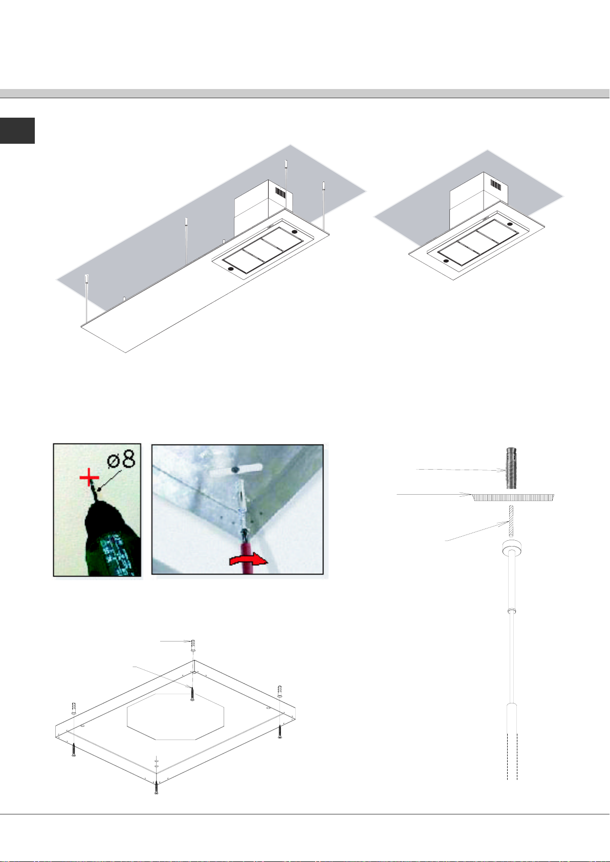
Installazione modello ad isola
L>120 cm
L=90 -120 cm
Esempio installazione Flat Kap con lunghezza
superiore a 120cm Esempio installazione Flat Kap con
lunghezza di 90 - 120cm
Posizionare la vela dove è prevista l’installazione, posizionare il piatto-muro all’interno del foro cappa nella vela,
riportare sul soffitto le posizioni dei fori, e dove presenti, riportare anche le posizioni dei tiranti, quindi forare e fissare
con tasselli/viti in dotazione
Vite
Tassello
Tassello
Barra filettata
Muro
3
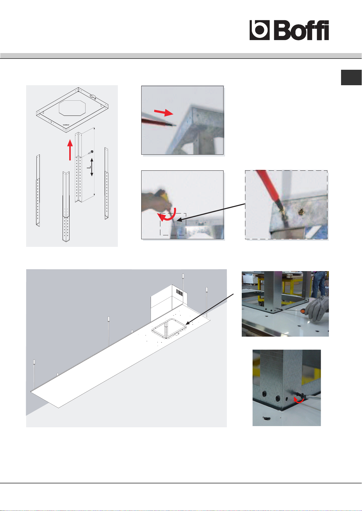
IT
Fissaggio angolari camino a piatto-muro sul con viti in dotazione
Fissaggio angolari camino a supporto gruppo aspirante Flat Kap

4
IT
Fissaggio corpo aspirante
Fissaggio tubo camino
Fissaggio carter camino
Fissare estremità con viti
5
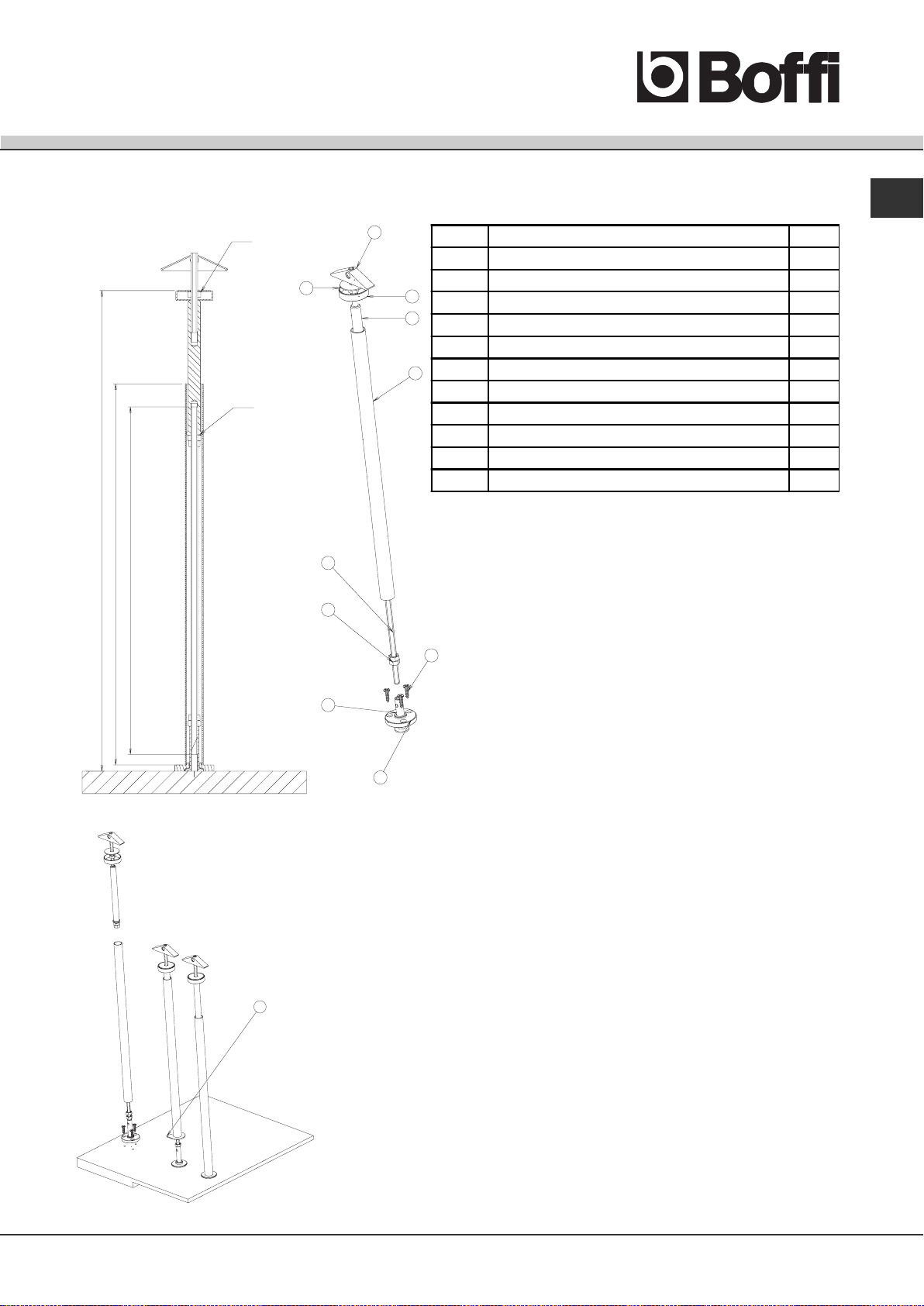
IT
H - 80
H - 110
A
3
45
6
8
7
1
10
9
2
428.9
310
340
Sequenza operazioni per montaggio kit tiranti
A - INSERIRE TASSELLO(3) BLOCCANDOLO CON DADO ESAGONALE (1)
B - INSERIRE FONDELLO (5)
C - AVVITARE MANICOTTO (6)
D - PREAVVITARE SU BARRA FILETTATA(7) 2 DADI ESAGONALI (1,vedi
dettaglio A) E QUINDI AVVITARE COMPLETAMENTE LA BARRA AL
MANICOTTO (6)
E – INSERIRE LA COPERTURA TIRANTE(8) BLOCCANDOLA CON LA
FORCELLINA(11) E 2 DADI ESAGONALI(1)
F - AVVITARE SU VELA FONDELLO(9) COMPLETO DI REGOLATORE(10)
G - PRENDERE LA VELA ED AVVITARE I REGOLATORI(10) ALLA BARRA
FILETTATA (7) FINO A LIVELLARE LA VELA
H - DOPO AVER LIVELLATO LA VELA BLOCCARE IL TUTTO CON DADI
ESAGONALI (1) E COPRIRE IL TUTTO CON LA COPERTURA TIRANTE (8)
11
Posizione Descrizione Quantità
1 DADO ESAGONALE NORMALE M6 UNI 5588 3
2 VITE 3,5x16 5
3 TASSELLO AD ANCORA M6 1
4 RONDELLA TASSELLO 1
5 FONDELLO DI CHIUSURA SUPERIORE 1
6 MANICOTTO DI COLLEGAMENTO TIRANTE 1
7TIRANTE 1
8 COPERTURA TIRANTE 1
9 FONDELLO DI BLOCCAGGIO TIRANTE PER CAPPA FLAT 1
10 REGOLATORE TIRANTE PER CAPPA FLAT 1
11 FORCELLINA 1
Montaggio kit tiranti
(
H) Distanza tra vela e soffit
to

6
IT
A
Omegafaretti
Punti luce
Preavvitare viti su
copertura vela
Dettaglio A
Asolescorrimento
per viti
Farscorrere le asoledell’
omega faretti sulle viti
Predisposizione faretti su modello isola
Collegamento elettrico faston faretti, al cablaggio del motore
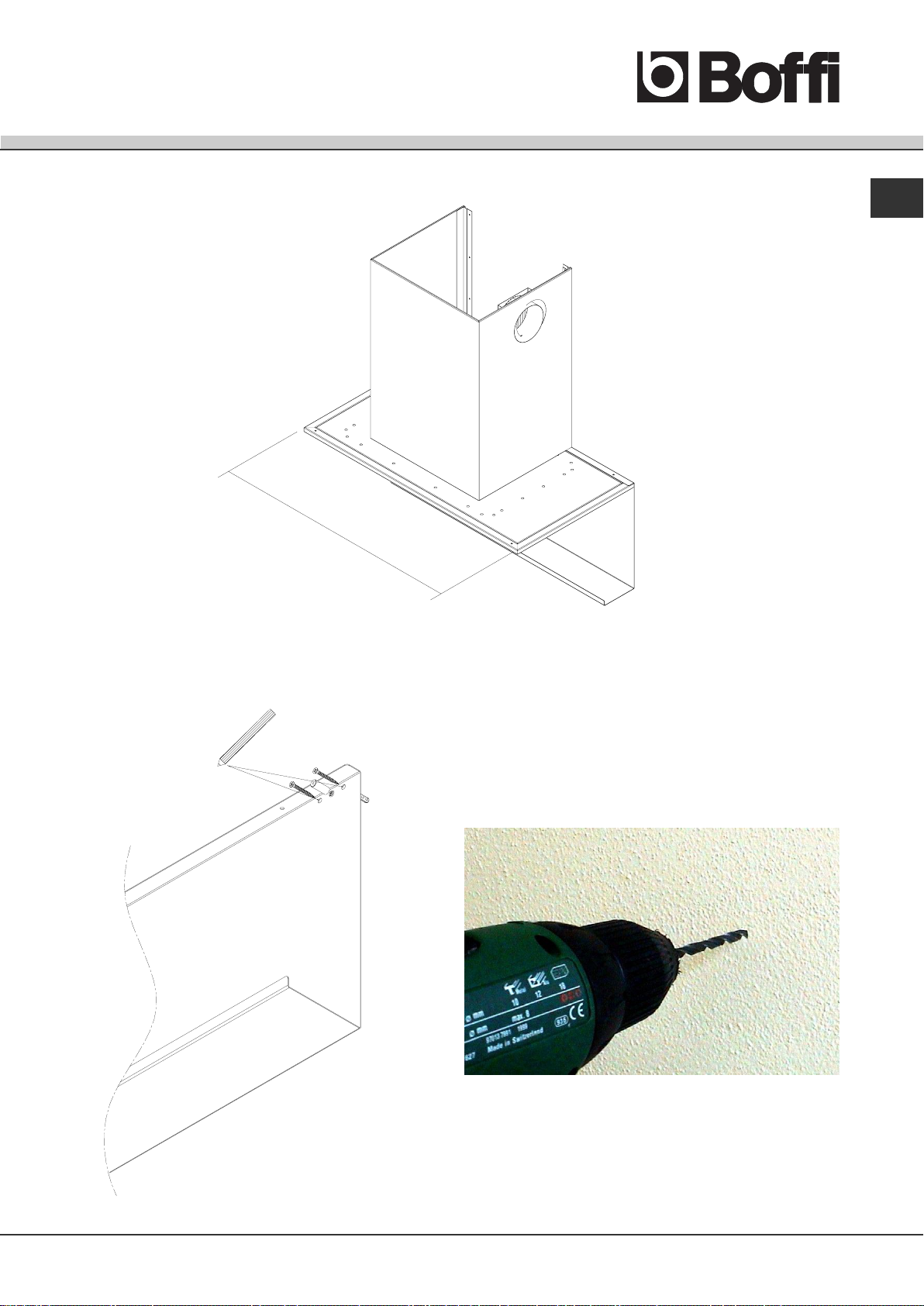
7
IT
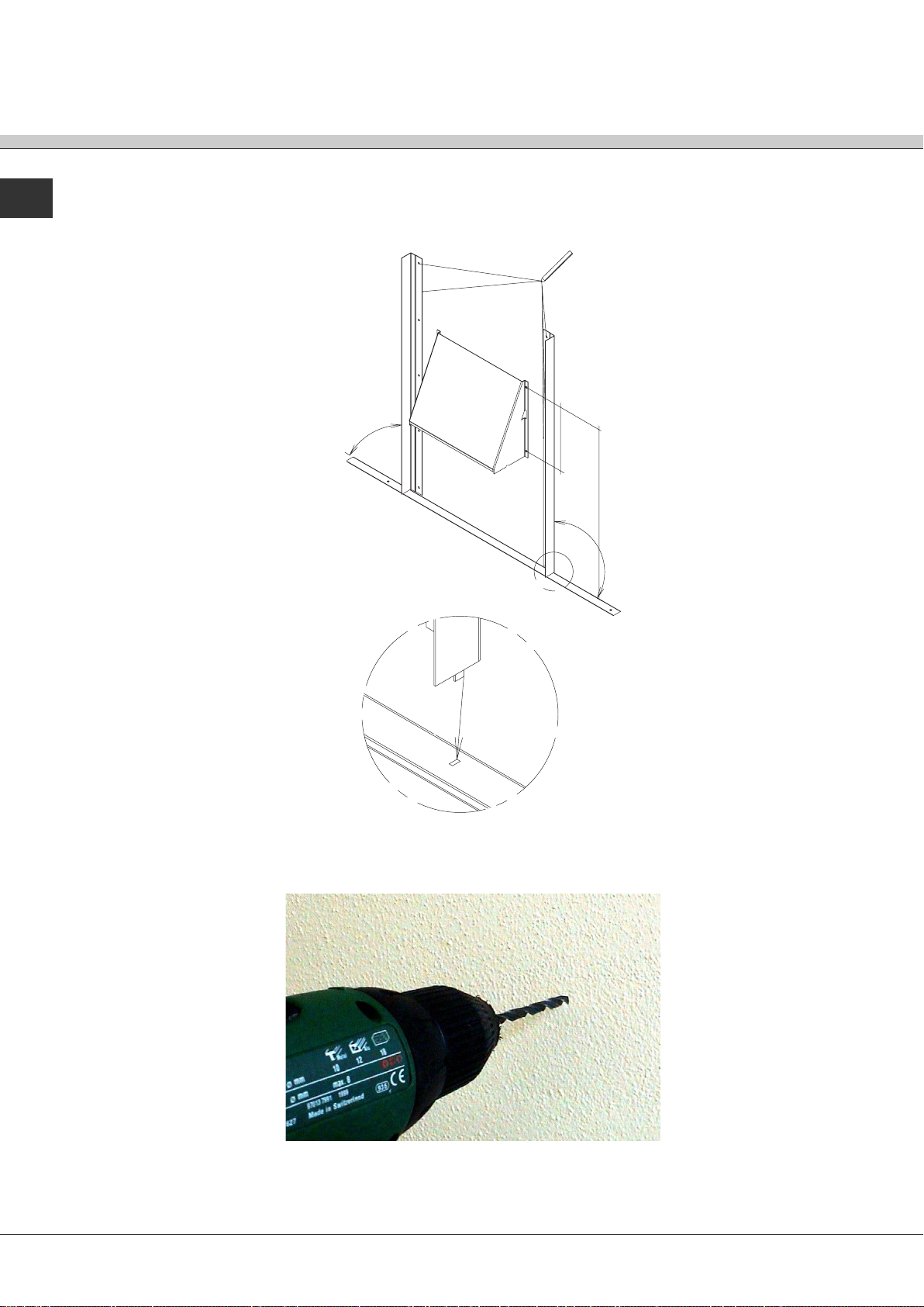
Installazione modello a parete
Posizionare lo schienale/angolare sulla parete, segnare riferimenti foro, forare e fissare con tasselli/viti in dotazione
Esempio installazione Flat Kap a parete
∅ 8∅ 8
∅ 8∅ 8
∅ 8
900 - 1200
8
IT Posizionaregliangolaridisostegnocamino,suiforidiriferimentodelloschinale/angolare,disporliperpendicolarmenteallostesso
segnare i fori e forare, fissare con tasselli/viti in dotazione
(posizionare la staffa di aggancio motore alla quota indicata rispetto allo schienale/angolare)
∅ 8∅ 8
∅ 8∅ 8
∅ 8
405
213.5
90˚
90˚
A
DETTAGLIO A
Other manuals for FLAT-KAP
1
Table of contents
Languages:
Other Boffi Ventilation Hood manuals


