Teka FilterCube 4-IFA User manual

Table of contents
1. General 3
2. Description of the system elements 4
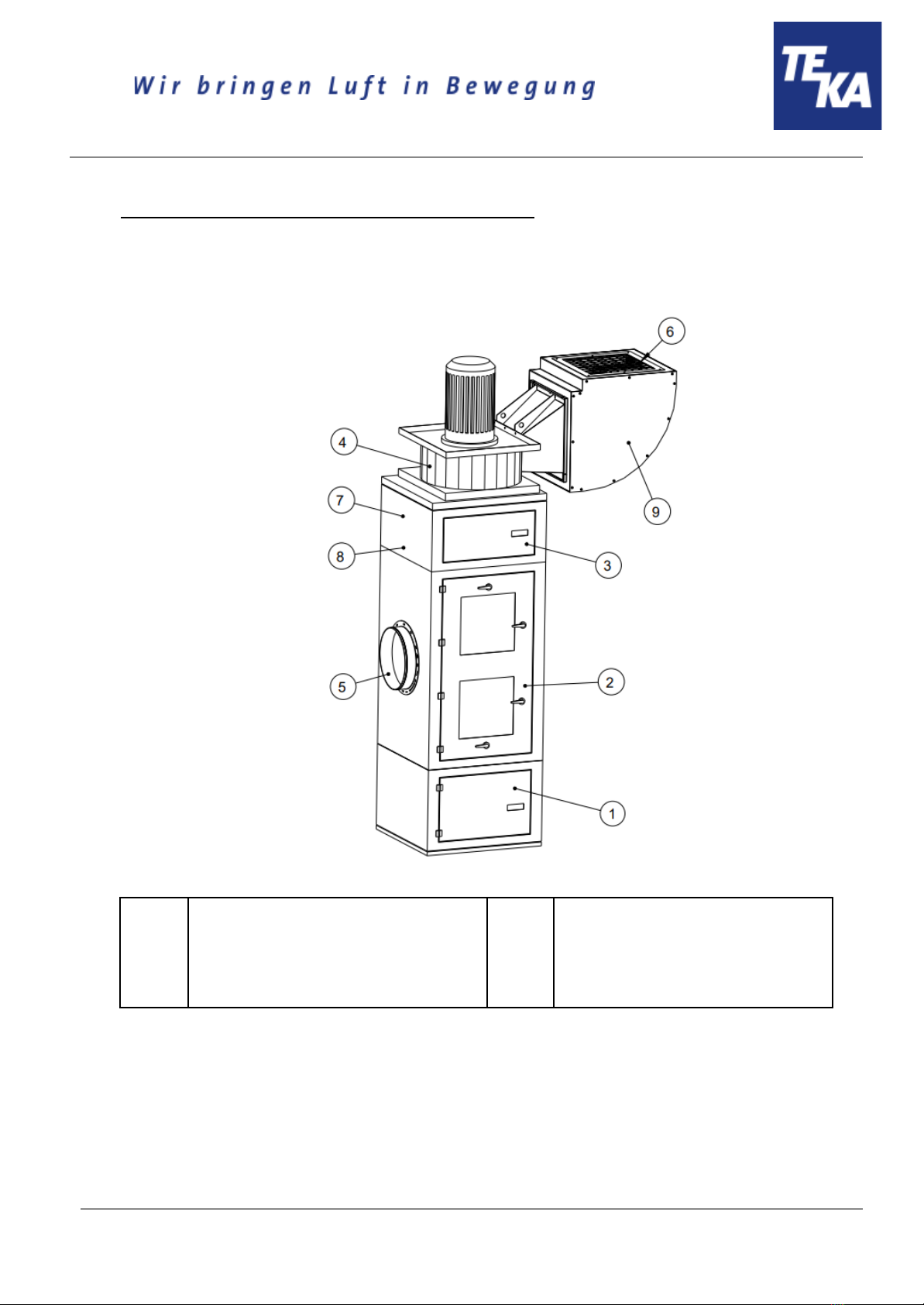
2.1. Illustration of the system elements 4
2.2. Functionality of the system 4
2.3. Intended use 5
2.4. Residual risk 5
3. Safety instructions 5
3.1. Definition of the hazard symbols 5
3.2. General safety instructions 6
4. Storage, transport and installation of the device 7
5. Commissioning 8
5.1. Connecting the suction line and exhaust air line 9
5.2. Electrical connection 10
5.3. Precoating of the filter cartridges 11
5.4. Connecting the compressed air supply 11
5.4.1. Compressed air supply for the cleaning of the filter cartridges 11
6. Operating the system 12
6.1. Explanation of the operating elements 12
7. Maintenance 13
7.1 Reset to maintenance state 14
7.2. Cleaning the filter cartridges 15
7.3. Replacing the filter cartridges 16
7.4. Emptying the dust collecting tank 22
7.5. Draining the condensate 23
7.6. Precoating of new filter cartridges 24
7.6.1. Feeding the precoat via a FVS (TEKA spark pre-separator) 25
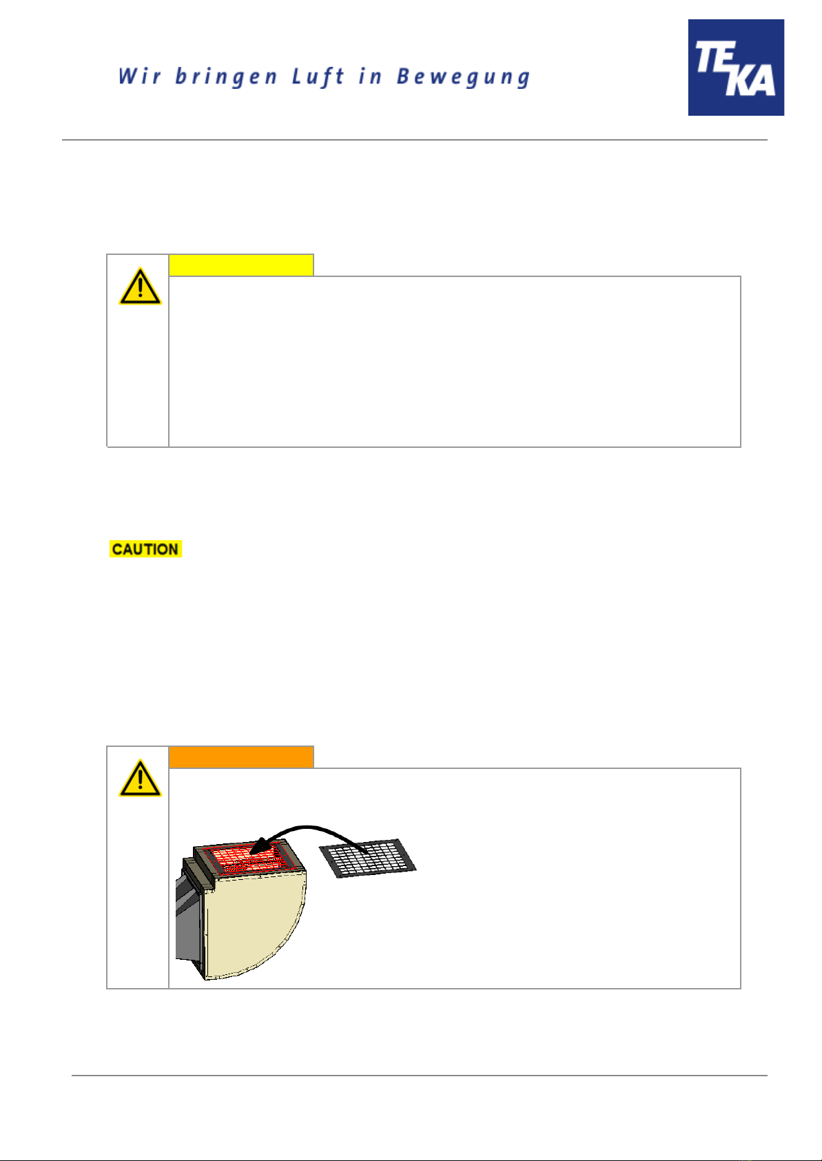
7.7. Cleaning/replacing the particle sensor 26
7.8. Replacing the filter mats at the control cabinet 27
8. Dismantling / Disposal 28
9. Diagnostics and troubleshooting 28
10. List of spare parts 30
11. Technical data 31
12. EC declaration of conformity 32
13. Training protocol 33
14. Maintenance intervals 34
14.1. Usage-related maintenance 34
14.2. General maintenance 35
14.2.1. Visual inspection of the device 35
14.2.2. Visual inspection of the pipelines for dust deposits 36
14.2.3. Visual inspection of the pneumatic pipes 36
BA_FilterCube_4_IFA_20230808_EN
2
08.08.2023

14.2.4. Functional test of the device 36
14.2.5. Electrical test of the electrical lines and earthing connections 37
14.2.6. Test of fixing of the mounted unit elements 37
1. General
Congratulations on purchasing the product from TEKA.
Our engineers ensure that our devices reflect the state of the art through continuous development.
Nevertheless, misuse or misconduct can endanger your safety. Please observe the following for a
successful use of the device:
Only authorised and instructed personnel can carry out transport, operation,
maintenance and repair of the device. The operator must ensure that the operating
personnel take note of these instructions.
Please read these instructions before operating the device, and observe the safety
precautions to avoid injury!
Store this manual in a safe place! These instructions are to be regarded as a component
of the product!
Adhere to all product notes!
Modifications or conversions that the operator carries out at the device without the
consent of the manufacturer, can lead to new safety hazards or to the loss of warranty
claims.
Observe the manufacturer’s instructions. Contact the manufacturer in case of any
uncertainty:
Tel: +49 2541-84841-0
E-mail: [email protected]
BA_FilterCube_4_IFA_20230808_EN
3
08.08.2023

2. Description of the system elements
2.1. Illustration of the system elements
Installation example:
Z.Nr. 21382701
Pos.1
Pos.2
Pos.3
Pos.4
Dust collecting housing
Filter housing
Cleaning housing
Fan
Pos.5
Pos.6
Pos.7
Pos.8
Pos.9
Suction nozzle
Exhaust air nozzle
Connection for compressed air
Drain valve for compressed air
Silencer
2.2. Functionality of the system
The filter unit serves to suck off and filter polluted air (according to the intended use). The air is purified
on the surface of the filter cartridge in the filter section of the unit. The separated dust is collected in a
dust collecting tank. An automatic filter monitoring indicates when a cleaning or a replacement of the
filters is necessary. The purified air is led outside via the exhaust air pipe or back into the working room.
BA_FilterCube_4_IFA_20230808_EN
4
08.08.2023

2.3. Intended use
The device is intended for commercial use. If the device is made publicly accessible, it must never be
operated unsupervised by authorized personnel, authorized by the operator.
The filter unit is intended for extraction and filtration of dusts and fumes that result from thermal joining
and cutting of metals. The filter unit is amongst others suitable for separating welding smokes of
unalloyed and alloyed steels as well as of high-alloy chromium-nickel steels and therefore meets the
highest welding fume separation category “W3” according to DIN EN ISO 21904-1 / -2.
WARNING
Improper use can damage parts and be a danger to life and limb!
The device must not be used for the extraction of oil-laden welding fume, explosive dust
and gases, hybrid mixtures, glowing or burning substances, gases, water, etc. The
device must not be operated in explosive zones.
Dangers arising from fire.
If the sucked medium is combustible fume or dust, the operator must determine
beforehand which fire protection measures are to be taken.
2.4. Residual risk
CAUTION
Danger due to possible hazardous materials in the exhaust air flow.
Because the unit does not monitor the quality of the air in the exhaust air flow, we
recommend that you always guide the exhaust air flow exiting our unit to areas (e.g. to the
outside into the open air) in which there is no danger to any living being. To do this, it is
necessary to fit a suitable exhaust air line at the filter unit.
3. Safety instructions
3.1. Definition of the hazard symbols
The device is constructed according to the state of the art and the recognised safety regulations.
Nevertheless, during use threats to life and limb of the user or other persons may arise. The impairment
of the machine or other property are also possible. In these instructions we warn by using corresponding
indications.
WARNING
WARNING
These instructions are made in case of risks that can lead to injury or death.
CAUTION
CAUTION
These instructions are made in case of risks that can lead to injury.
BA_FilterCube_4_IFA_20230808_EN
5
08.08.2023

NOTICE
NOTICE
These instructions are made in case of risks that can lead to material damages.
Information notes are no hazard warnings; they call attention to useful information.
3.2. General safety instructions
WARNING
Dangers arising from improper use / unauthorised operations.
The operator must ensure that their authorised personnel are familiar with all the safety
indications in this manual in advance. The operator is responsible for ensuring that all work
is carried out by authorised and qualified personnel. We therefore recommend using the
training protocol on the last page for that purpose (see chapter “Training protocol”).
Laymen are allowed to operate the device after having received the necessary instructions.
But they are not allowed to carry out any installation, repair or maintenance work.
Dangers arising from fire.
In case of fire, if possible, switch the unit immediately off or disconnect it from the power
supply. Fire extinguishing measures which the operator is obliged to determine beforehand
must be initiated immediately.
WARNING
Dangers arising from electricity.
The operator must ensure that electrical plants and equipment are only built, modified and
maintained by a qualified electrician or under the direction and supervision of a qualified
electrician. Do not work on components if you are not sure that these are disconnected. If
necessary, disconnect the device from the electric power supply and secure it against
unauthorized restarting.
BA_FilterCube_4_IFA_20230808_EN
6
08.08.2023

4. Storage, transport and installation of the device
WARNING
Risk of injury from tilting or unmounted components when stored or transported.
The device must be secured against tilting and slipping when it is stored or transported. Do
not stand under or next to the floating load. Lift trucks, forklift trucks and transport cranes
must have a sufficient minimum load bearing capacity.
Dangers arising from titling or functional impairments at its destination.
The unit may only be set up on a suitable surface. The unit may only be set up on a suitable
surface. The surface must be vibration-free and horizontal. The operator must check the
bearing capacity of the surface. The unit must be secured on the surface, for example using
lag bolts or stud bolts.
NOTICE
Damage or functional impairment of the unit due to climatic influences.
The unit must be stored in a dry place and protected against moisture during transport. As a
matter of principle, the filter unit is not designed to be installed outdoors. In this case contact
the manufacturer in order to find out if a caping or a trace heating system are necessary.
● First the filter unit as delivered must be transported to its destination. There the filter unit must
be moved to an upright position. Therefore, lift the filter unit with lifting tools:
Unit type 1 (with sound insulation housing): Use the 4 lifting rings (A).
Unit type 2 (without sound insulation housing): Use the 4 lifting rings (B) at the fan housing.
Unit type 3 (with fan attached alongside): Use the lifting rings (C) for the filter unit. You can
move the fan by lifting it with fork lift forks underneath the bottom (D) of the fan.
Use appropriate lifting tools (forklift truck, transport crane,...) with a
minimum load-carrying capacity of 1000 kg. The filter unit must be secured against tilting
and slipping when it is moved, lifted or put down. No one is allowed to stand under or
beside the load. Use only appropriate ladder tools.
● For setting up the filter unit at its precise designated position, you can use the methods
mentioned for each unit type. When the mentioned method is used, it may only be transported a
short distance. The filter unit must be set up and fixed on a suitable surface.
BA_FilterCube_4_IFA_20230808_EN
7
08.08.2023

5. Commissioning
WARNING
Dangers arising from a defective condition of the unit.
Make sure that the measures described in this chapter are completed before the
commissioning of the unit. All doors of the unit must be closed and all necessary connections
must be attached before turning the unit on. Do not operate the unit if any components are
defective, missing or damaged. Check the orderly condition of the unit before switching it on.
The unit must not be operated without a filter element.
NOTICE
Damaged supply lines.
Make sure that the supply lines are protected against damage by forklift trucks and similar
events. Protect all supply lines from heat, moisture, oil and sharp edges.
BA_FilterCube_4_IFA_20230808_EN
8
08.08.2023

5.1. Connecting the suction line and exhaust air line
For extracting the contaminated air, a suction line must be connected to the suction nozzle (see chapter
2.1).
CAUTION
Danger for the respiratory tract arising from polluted ambient air. Dust deposits in the
suction pipe are possible.
Only operate the system if the necessary suction line is fitted. The suction line must be
dimensioned according to the application in such a way that, if possible, no dust deposits
occur in the suction line. If this has not already been carried out by TEKA, a suitably qualified
employee must be consulted. If the suction line includes extraction elements (e.g. suction
arms, pipe grills, etc.), these must also be included in the layout. If this is the case then users
must be informed of whether extraction elements can be used simultaneously and, if this is
possible, then which. The regulating devices (e.g. throttle valves) of each single extraction
element must also be set appropriately during the final commissioning.
Depending on the application, the suction pipe must be equipped with extraction elements (suction arm,
extraction hose, round duct grille, etc.). When using a capture element with an extractor cowl, the
extractor cowl must follow the weld seam, if possible by using the movement of the welding fume
caused be thermal influences.
You have to make sure that connections between the workpiece and the suction
hood (and in general between the workpiece and the filter unit) are avoided in order to prevent
the welding current from flowing back to the welding machine via the protective conductor of the
filter unit.
If the air shall be directly sucked off by an upstream machine, the suction line must be connected to the
capture opening of the upstream machine.
The exhaust air pipe must be attached to the exhaust nozzle (see chapter 2.1).
In the case of an optional fan housing standing alongside, the filter unit and the fan must be connected
by means of a connecting pipe.
WARNING
Danger to life when reaching the fan impeller.
The exhaust air pipe must be attached before the commissioning.
If no exhaust air pipe is attached, the protective grille of the silencer must be installed.
BA_FilterCube_4_IFA_20230808_EN
9
08.08.2023

5.2. Electrical connection
WARNING
Risk of electric shock.
Electrical plants and equipment may only be built, modified and maintained by a qualified
electrician or under the direction and supervision of a qualified electrician. Do not work on
live electrical components and elements if you are not sure that these are indeed
disconnected. If necessary, disconnect the device from the mains. The operator is
responsible for a potential-free balance of the equipment.
If the unit is equipped with a frequency converter, then it may only be operated on networks
with an AC/DC sensitive RCCB. For frequency converter operation, the cross section of the
protective conductor
● must be at least 10mm²,
● and must be at least equal to the size of the operator side outer conductor
cross-section.
CAUTION
Health hazard arising from unintentional cleaning processes.
Switch on the control only if the unit is in operational condition.
NOTICE
Electric malfunction possible in cause of an incorrect power supply.
Pay attention to the admissible supply voltage. Please observe the specifications on the type
plate.
● Mount the housing of the external control (if it is not mounted on the device itself) close to the
device on the wall or at any other appropriate mounting point. Or mount the control together
with a cabinet console on a suitable surface, for example using lag bolts or heavy-duty anchors.
The housing is not suited for outdoor installation.
● Connect all visible cables and hoses are according to their functions. When delivered they are
labelled according to their functions. When connecting to the control, please observe the
specifications on the circuit diagram which is attached to the control.
● Connect the unit to the power supply.
● Check if the direction of fan rotation is correct (This is not necessary in the case of units with a
frequency converter). A wrong rotation direction can be identified thanks to the sticker sticked to
the fan scroll which is showing the direction. Compare the rotation direction on the sticker to the
rotation direction of the motor cooling fan when the motor is running down after being switched
off. If the motor rotates in the wrong direction, disconnect the device from the power supply and
exchange two phases at the supply line to the control.
When the fan rotates in the wrong direction, the extraction capacity is
reduced.
BA_FilterCube_4_IFA_20230808_EN
10
08.08.2023

5.3. Precoating of the filter cartridges
For a longer service life of the filter cartridges they are pretreated with a filter aid in the factory.
If the fan unit and the filter unit of the filter device are only connected to one another
on site, then the filter cartridges have not yet been pretreated at the factory. Then the precoating
can only be carried out during the commissioning at the operation site.
When the operator orders and installs new filter cartridges, we recommend to also precoat them before
the commissioning.
Please read and refer to "Precoating new filter cartridges" in the chapter "Maintenance". There
you can also find a description of the operating method of the precoat.
5.4. Connecting the compressed air supply
NOTICE
The compressed air must be dry and oil-free.
According to ISO 8573-1:2010 the compressed air quality must at least meet: [7:4:4]
➔Particle size: <40µm
➔Pressure dew point: <= +3°C
➔Oil content: <=5mg/m³
5.4.1. Compressed air supply for the cleaning of the filter cartridges
The filter cartridges of the system are automatically cleaned. Cleaning is carried out pneumatically via a
built-in compressed air tank.
Without compressed air supply the filter cartridges will become dirty very quickly.
● The external compressed air supply must be assured with an approved compressed air hose.
For the connection to the device, the compressed air hose must be equipped with a quick
coupling for an insert sleeve DN 7.2.
The compressed air must be dry and oil-free.
● The operating pressure of the compressed air supply must be a minimum of 3 bars and
maximum of 4 bars.
In case of the pressure being too low, the compressed air tank does not reach
quickly enough the operating pressure for the following cleaning. There is a risk of
material damage when the pressure is too high.
● Connect the compressed air hose to the insert sleeve (see chapter 2.1).
BA_FilterCube_4_IFA_20230808_EN
11
08.08.2023

6. Operating the system
6.1. Explanation of the operating elements
Control functions, setting options for programs, menu navigation, error messages, etc. are
described in the enclosed operating manual of the unit control. There is also an explanation of the
elements of the control panel.
Operating elements for the device control
Representa
tion
Designation
Description / function
Main switch
●OFF: The device is disconnected from the power supply.
●ON: The device is connected to the power supply and
ready to operate.
The main switch also serves as an emergency
off switch.
Operating elements for status and error messages
Representa
tion
Designation
Description / function
Stroboscope flash
The stroboscope flash draws attention to an error message of
the device control by flashing up. The error message is shown
on the display of the control.
BA_FilterCube_4_IFA_20230808_EN
12
08.08.2023

7. Maintenance
In accordance with national regulations, the operator is obliged to carry out repeat and functional tests.
Unless otherwise specified by national regulations, we recommend regular visual inspections and
functional tests of the device as described in the chapter “Maintenance intervals”.
You find the chapter “Maintenance intervals” at the end of the document. The general
maintenance (visual inspection, etc.) is also explained there.
In the chapter “Maintenance intervals” there is information on the maintenance intervals of the filter
elements. But these are only recommendations. Depending on the application (multi-shift operation,
dust generation, ...) it may be necessary for the operator to change the maintenance intervals.
In this chapter the maintenance work which is caused by wear caused during operation is described.
WARNING
Work on the open system entails the risk of electrical shock or accidental restart the
system. Both pose a danger to life and limb.
When cleaning and servicing equipment during the replacement of parts or when changing
to another function, set the device to maintenance condition first (see chapter “Reset to
maintenance state”).
A recommissioning of the device must only occur if it is ensured that the device is
functionally equivalent to the original state.
CAUTION
Hazards to the respiratory tracts are possible due to contact with contaminated filter
elements.
All maintenance work must only be carried out in well-ventilated rooms and while wearing an
appropriate respiratory mask! We recommend: respiratory protection half mask DIN EN
141/143 protection level P3. For all maintenance work ensure a cautious handling of filter
elements and components in order to avoid whirling up dust.
The operator is obliged to store and dispose of the collected dust in accordance with national or
regional regulations. For all maintenance or cleaning work please refer to the applying
environmental regulations. Pollutants and filter elements must be disposed of or stored according
to the regulations as well. If you have any doubts, we recommend contacting a disposal
contractor in your area.
BA_FilterCube_4_IFA_20230808_EN
13
08.08.2023

7.1 Reset to maintenance state
● Switch off the unit. Then disconnect the unit from the power supply by setting the main switch in
the “OFF” position. Secure the unit against unauthorized restarting during maintenance.
● Disconnect the compressed air hose of the external compressed air supply from the insert
sleeve (see chapter 2.1). Empty the compressed air tank by opening the drain valve (see
chapter 2.1) with a suitable screwdriver. Minor quantities of condensation water can leak out
when opening the drain valve. Close the drain valve when the compressed air tank is entirely
empty.
When opening the drain valve a compressed air blast can occur!
This step is not necessary if the unit is equipped with the safety upgrade. This
contains a 3/2-way valve which automatically empties the compressed air tank when the
unit is switched off.
● After completion of all maintenance work the unit can be reconnected to the power supply and
the external compressed air supply.
BA_FilterCube_4_IFA_20230808_EN
14
08.08.2023

7.2. Cleaning the filter cartridges
CAUTION
A sudden jet of compressed air and huge amounts of whirled up dust are possible
due to an automatic cleaning with an opened service door.
During the operation of the device, the service door of the filter housing must not be opened.
The same applies to the ready to operate condition (standby) as there is also the possibility
of an automatic cleaning (subsequent cleaning).
The filter cartridges are reusable filters and can be cleaned. The cleaning of the filter cartridges is
automatically carried out.
The degree of pollution of the filter cartridges is electronically monitored. In order to assure the required
extraction capacity of the device, the cleaning of the filter cartridges starts automatically when a preset
differential pressure value is reached. If the preset differential pressure value is not undercut after the
cleaning of the filter cartridges, another cleaning starts. The filter unit remains in operation during the
automatic cleaning. The compressed air blast is produced in opposite direction to the intake. The
cleaned dust falls downwards in the dust collecting tank.
Depending on the setting of the control unit there can be automatic postcleanings of the filter cartridges
even when the unit is switched off.
When the maximal admissible differential pressure value is reached, the device triggers an alarm (see
chapter “description of the control elements”). If despite of the automatic cleaning of the filter cartridge
the alarm value is not undercut anymore, the filter cartridge must be replaced. (see chapter: “Replacing
the filter cartridges”).
The differential pressure values in the control unit that initiate a cleaning or a filter alarm are preset
values adapted to the filter unit. Please find detailed information concerning the functioning in the
enclosed operating instructions of the control unit.
When using optional extraction elements with a suction hood, their throttle valve must be closed as
soon as the device is switched off. Otherwise dust can escape from the suction hood in case of possible
automatic subsequent cleanings.
BA_FilterCube_4_IFA_20230808_EN
15
08.08.2023

7.3. Replacing the filter cartridges
Replacing the filter cartridges becomes necessary when the filter cartridges are saturated with dirt in a
manner that despite of the cleaning the filter alarm is triggered again at very short intervals or
permanently. (The filter alarm is described in chapter “Cleaning the filter cartridges”.)
CAUTION
Whirling up dust is possible due to the polluted filter cartridges. Danger of
unintentional automatic cleaning with the unit switched off.
The filter cartridges must be cleaned before being replaced. This is done by carrying out 3
manual cleanings via the unit control (see separate operating instructions). The filter unit
must be switched off beforehand but without disconnecting the unit from the power supply.
After the cleaning, disconnect the filter unit from the power supply and secure it against
being switched on again. After cleaning the filter cartridges wait about 5 minutes before
opening the service door of the filter housing.
We recommend to pretreat new filter cartridges with filter aid (e.g. precoat) before the first
commissioning. Refer to the chapter "Precoating new filter cartridges".
BA_FilterCube_4_IFA_20230808_EN
16
08.08.2023

● We recommend that two people work
together to replace the filter cartridges.
● We recommend spreading out a protective
film in order to keep the area around the unit
clean.
●The filter cartridges may only
be replaced in well-ventilated rooms and
while wearing an appropriate respiratory
mask! We recommend: Respiratory
protection half mask DIN EN 141/143
protection level P3.
● We also recommend using additional
protective clothing such as gloves,
disposable overalls and protective eyewear.
● Before replacing the filter cartridges, make
sure you have a suitable container (e.g. PE
bag) for disposal.
The contaminated filter
cartridges must be packed in a suitable
container (e.g. PE bag). PE bags are
available as an option (see spare parts
list)! We recommend that you procure
disposal bags at an early stage.
● Open the filter housing’s service door by
opening the door handles. When doing this,
it is necessary to use a double-bit key to
open the door handle that is equipped with a
lock.
● Loosen the fixing screw. This is located at
the bottom of the cartridge holder. Loosen
the fixing screw but do not unscrew it from
the cartridge holder It is important that the
cartridge holder is still held loosely.
BA_FilterCube_4_IFA_20230808_EN
17
08.08.2023

● Pull the disposal bag over the cartridge
holder and filter cartridge.
● Unhook the cartridge holder from the
cartridge guides.
● Remove the cartridge holder with the filter
cartridge and the disposal bag from the filter
housing.
● Briefly lift the filter cartridge in order to
release it from the cartridge holder.
● Next, pull the cartridge holder with little dust
on it out of the disposal bag and past the
filter cartridge.
● Insert the bag into the inside of the filter
cartridge at the top.
● Then place the filter cartridge on its side.
BA_FilterCube_4_IFA_20230808_EN
18
08.08.2023

● Undo the cylindrical nut. This is located at
the base of the filter cartridge. When doing
this, do not grip the cylindrical nut directly
with your hands but from outside through the
bag.
● Place the filter cartridge upright again.
Remove the cylindrical nut from the bag.
● Remove the displacer from the filter
cartridge.
● Seal the disposal bag (e.g. with cable ties).
The operator is obliged to store and
dispose of contaminated filter
cartridges in accordance with
national or regional regulations.
.
●First of all, remove all the filter cartridges as described in the steps above.
●Only then should you start to install the new filter cartridges.
Only use TEKA replacement filters. Otherwise the correct functioning of the unit
is not guaranteed.
BA_FilterCube_4_IFA_20230808_EN
19
08.08.2023

● Insert the displacer into the new filter
cartridge in such a way that the displacer’s
screw passes through the opening in the
base of the filter cartridge.
Check whether the seal is in
contact at the thread of the displacer and
that it is undamaged. Otherwise, it is
necessary to use a replacement seal (see
spare parts list).
● Screw the displacer tight with the cylindrical
nut.
When you do this, the side of
the large chamfer (A) of the cylindrical
nut must face outwards.
● Insert the cartridge holder without a new filter
cartridge in one of the cartridge guides.
However, only do this for one side. The other
side of the cartridge holder should continue
to hang freely.
BA_FilterCube_4_IFA_20230808_EN
20
08.08.2023
Table of contents
Other Teka Ventilation Hood manuals

Teka
Teka DH 80T Series User manual

Teka
Teka CNL1-3000 User manual

Teka
Teka DHT 97670 ROS WH User manual

Teka
Teka DH ISLA User manual

Teka
Teka GFL 651 EOS User manual

Teka
Teka TL-2000 User manual

Teka
Teka DG 80 Series User manual

Teka
Teka DVS 983 BK User manual

Teka
Teka Pertecta4 DLH 985 User manual

Teka
Teka DPE User manual