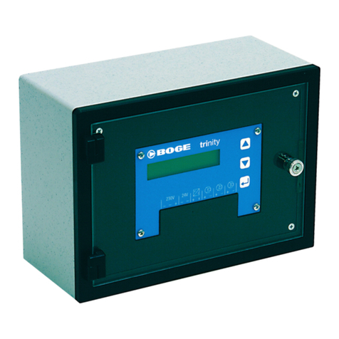
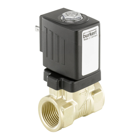
Boge airtelligence PROVIS User manual

Operating
instructions
Control for
several compressors
airtelligence PROVIS


BOGE Operating instructions for airtelligence PROVIS
Inhalt.pm6.5 - GB
Page I
Operating instructions
airtelligence
PROVIS
Issue: 11/2008
No. 596.0899.01
Nominal price: €5,00
BOGE KOMPRESSOREN
Postfach 10 07 13
D-33507 Bielefeld
Otto-Boge-Straße 1–7
D-33739 Bielefeld
Fon: ++49 / 52 06 / 6 01-0
Fax: ++49 / 52 06 / 6 01-200
Mail: info@boge.com
Net: www.boge.com

Page II BOGE Operating instructions for airtelligence PROVIS
Inhalt.pm6.5 - GB

BOGE Operating instructions for airtelligence PROVIS
Inhalt.pm6.5 - GB
Page III
Index
Index
1.1 General safety instructions ........................................................ 1.1
1.1.1 Safety instrutions for operation the control .................................... 1.1
1.1.2 Safety instructions for servicing and repairing the control ............. 1.1
1.2 Introduction ................................................................................. 1.2
1.2.1 Correct use.................................................................................... 1.3
1.2.2 Inadmissible use ........................................................................... 1.3
1.2.3 Transport damage .........................................................................1.4
1.2.4 Customer service .......................................................................... 1.4
1.3 Product description .................................................................... 1.5
1.3.1 Installation and adjustment............................................................ 1.5
General

Page IV BOGE Operating instructions for airtelligence PROVIS
Inhalt.pm6.5 - GB

Allgemein.pm6.5 - GB
Page 1.1
General
BOGE Operating instructions for airtelligence PROVIS
Nonobservance of the following safety instructions may lead to injuries
and damage to the control.
Also observe the generally valid safety and accident prevention regu-
lations in addition to the information in these operating instructions!
1. Ensure that no commissioning and maintenance work on the controlis
undertaken until these operating instructions are understood.
2. Only use the control for its intended use, as described in these operating
instructions.
3. The owner must ensure
– that only appropriately trained and authorized personnel work on this
control.
– that the operating, maintenance and repair personnel has been
made fully familiar with all safety instructions, and that they are being
observed.
– that the control is only operated in a safe operating condition.
4. Only operate the compressor using the additional equipment (options)
recommended or authorized by the manufacturer.
5. Never start the control when one or serveral parts (e.g. cable, plug) are
damaged, when not in perfect working order, when damage is detected
or suspected.
1. Ensure that maintenance work is only carried out by appropriately
trained persons.
2. Ensure that setting work, malfunction rectification and repair is only
carried out by qualified electricians (see DIN VDE 0100 or DIN VDE
0013 EN 60204).
3. Prior to maintenance or repair work:
– Switch off the main switch.
– Check that no parts are under voltage.
4. Work on voltage carrying parts and devices are not permitted. Exceptions
are governed by the appropriate regulations, e.g. DIN VDE 0105.
5. Only use original spare parts, compressor oils and operating materi-
als released by BOGE during repair or maintenance.
1.1.1
Safety instructions
for operation
of the control
1.1.2
Safety instructions
for servicing and
repair of the control
General safety instructions1.1

Page 1.2
Allgemein.pm6.5 - GB
General
BOGE Operating instructions for airtelligence PROVIS
The purpose of these operating instructions is to familiarize the user with the
function and all application possibilities of the control.
These operating instructions contain important information on how to operate
several compressors safely, economically and according to intended use,
with the aid of an MCS control.
Observing these operating instructions will assist in avoiding danger, to
reduce repair costs and down times and to increase the reliability and service
life of the compressors.
It contains important information concerning the required parameters and
settings, and assists in case of malfunctions.
The operating instructions must be available to the control and compressor
operating personnel at the place of operation, at all times.
The operating instructions must be carefully read and applied by all persons
engaged to undertake the following work on the compressor:
– Operation, including fault rectification
– Commissioning
Introduction1.2
1.2
Correct use

Allgemein.pm6.5 - GB
Page 1.3
General
BOGE Operating instructions for airtelligence PROVIS
1.2.1
Correct use
This BOGE multiple system control including its options is intended for the
control of several screw and piston compressors.
It may only be operated and adjusted by trained and authorised people.
Requirements for compressors to be controlled
If the master control is ordered with compressors, we install the interface in
the compressors in the factory (forced option). If the compressors are already
installed, it will be necessary to meet the requirements for the master control.
These are normally:
1. A potential-free contact "Ready" (2 terminals)
2. Two terminals in series with the pressure switch installed in the compres-
sor.
3. A potential-free contact "Operation" (2 terminals).
4. A potential-free contact "Fault" (2 terminals).
For compressors with proportional control or frequency control please
contact BOGE.
Care must be taken with other makes; always obtain approval from the
factory.
This BOGE control is not explosion protected.
Do not operate in explosive areas!
The following is not permitted:
– Exceeding or going below the specified operating voltages
– Operation of the control by unauthorized or untrained persons
– Connection of unsuitable compressors
– Too high room temperatures > 45°C
1.2.2
Inadmissible use
Introduction1.2

Page 1.4
Allgemein.pm6.5 - GB
General
BOGE Operating instructions for airtelligence PROVIS
BOGE does not accept any liability for breakage or transport damage.
Please inspect the compressor immediately after delivery and direct damage
claims to the last haulier – even when the packing is not damaged!
To safeguard claims against the haulier we recommend leaving the machine,
devices and packing material in the same condition as they were in when
the damage was detected.
In the event of any other complaints, please inform us within six days after
arrival of the delivery.
The BOGE customer service is, of course, at your disposal.
Please contact us on:
Telephone: ++49 / 52 06 / 6 01-0
To avoid delays, always specify the following details about your control:
1. Software version
2. Circuit diagram number
3. Job number
4. Machine number
5. Type
6. Year of manufacture
ATTENTION!
Only BOGE service technicians or persons authorized by BOGE in writing
may repair or alter the control during the warranty period. Otherwise all
warranty claims will expire!
1.2.3
Transport damage
1.2.4
Customer service
Introduction1.2

Allgemein.pm6.5 - GB
Page 1.5
General
BOGE Operating instructions for airtelligence PROVIS
1.3.1
Installation and
adjustment
– The electronic pressure sensor must always be fitted verticaly (plug
upwards) on the common receiver or pipelines and free of condensate
water.
– If the air is damp (eg, system without dryer), it will be necessary to verti-
cally install between the muff and pressure sensor a 150 mm pipe.
– The cutout point of the pressure switches of the individual compressors
must be set at least 0.2bar higher that the upper cutout point of the master
control.
Attention!
The maximum operating pressure of the individual compressors may not be
exceeded.
– The pressure switches of the compressors are only used to allow opera-
tion in the event the master control fails.
Attention!
In the adjustment sequence the sub-menu "Pressure thresholds" must first
be checked and adjusted; thereafter the sub-menus general parameters;
"Compressor data" must be adjusted in this order.
– These operating instructions are only valid in conjunction with the appro-
priate circuit diagram.
– Instructions for making adjustments are given in the individual chapters.
Commissioning, adjustment, troubleshoorting and repairs may only be
performed by qualified electricians (see DIN VDE 0100, DIN VDE 0113 and
DIN VDE 105).
Product description1.3

Page 1.6
Allgemein.pm6.5 - GB
General
BOGE Operating instructions for airtelligence PROVIS

airtelligence PROVIS
Operation manual with Web-Server
V 15-01-2008

Pmax
Pmin
25
25
25
13
7
m³/min
airtelligence PROVIS combines compressors of different sizes to an optimum unit
Almost the best strategy to save energy
Load
Energy
- only program the compressor capacities
- set the common pressure switch points
- mount the pressure transducer
- connect the cables
The compressors will be controlled by the real air consumption
Within only 1 pressure difference for all compressors
Un-loadsaving
Vers i on 2 . 603 Jan 26 2007 14 : 35 : 07
Ser i a l number = 2401 -01611560
MAC adress = 00 . 50 .C2 . 64 . 4F. 97
DE
W
PO I NT TEMPERATURE
1.3°C 18.7°C
. 603AM-2-07-V
2m3/min
37.7.05 bar
◄►
For program version and serial number press button
Load energy saving

SUMMARIES
PART 1 airtelligence PROVIS
Page 1 Summaries
Page 2 Functional description
Page 3 Display and Key control
Page 4 Various speed compressor
Page 5 Configuration for various speed Compressors
PROGRAMMING THE COMPRESSOR CONTROL
Page 6 Compressor capacities
Page 7 Pressure und rank profiles
Page 8 Analog and Digital Inputs on airtelligence PROVIS
Page 9 Analog und Digital inputs on connection modules
Page 10 Real time clock
Page 11 Clock – programming notices
Page 16 IP-address
STATUS DATA and COMMISIONING
Page 12 Status data of compressors and connection modules
Page 13 Commisioning and switching functions
PART 2 WEB-Server ONLINE Visualization
Page 15 Software - Version
Page 16 Programming IP-address
Page 17 Web Server installation
Page 18 Select data directory
Page 19 User interface
Page 20 OFFLINE evaluation
Page 21 Select different Diagrams
Page 22 Energy calculation, service and alarm report
Page 23 Fundamental settings
Page 24 General settings
Page 25 UPDATE with Admin-Tool. Create new compressor stations
PART 3 Measurement, configuration and connection drawings
Page 27 Measurement of the housing
Page 28 airtelligence PROVIS measuring drawing
Page 29 Connection name
Page 30 Connection schematic
Page 31 Configuration of connetion module
Page 32 Measure drawing of connection module
Page 33 RS-485 connection schematic
Page 34 Compressor load / unload connection
Page 35 Compressor remote / local schematic
Page 36 Digital and analog inputs of connection module
Page 37 Analog inputs and outputs of connection module
Page 38 Digital inputs and outputsof airtelligence PROVIS
Page 39 Analog inputs and outputs of airtelligence PROVIS
1

FUNKTIONAL DESCRIPTION
airtelligence PROVIScombines compressors of different sizes
to an optimum unit which automatically adapts to the production based on the current compressed air consumption.
It is madesure that it is always themost efficientcompressor combination which generates the compressed air
necessary for production, independent of the manufacturer and the performance. The system pressure remains
within the smallest limits. It is seen that the costs are kept as low as possible. The compressor performances and a
common pressure difference are programmed in for all the compressors.
Based on this information, airtelligence PROVIS permanently calculates the current compressed air consumption
and the volume of the compressed air system. The self-learning 8-fold calculation depth makes it possible to adapt
the compressors to the changes in consumption in a dynamic way.
Automatic compressor change as per compressed air consumption
If all the compressors are on the same rank, they are working fully automatically and based on real air
consumption. The priority of the compressors is adapted to the production process in real time with a useful
hysterisis calculation. It is always the compressor combination with the lowest cycle rates which is running and thus
with the lowest idle times. Big compressors are only running when needed. The smaller compressors are running
under load instead of idling the big compressors. The compressors auto-regulate the motor start limitations.
The status of the compressors is constantly monitored.
If a running compressor displays a malfunction within the pressure range or is switched off for service, its
performance is taken over by other compressors. If several compressors are needed to do this, addition is made
time-delayed. Load and total running times are stored for the individual compressors. The operating hours are
deleted, if required.
Connecting of compressors
is effected using the connecting moduls this being installed in the electrical housing of the compressor on the DIN-
rail. The connection to theMaster control is made over the industry us RS 485 bus. The operating voltage of 24
volts AC/DC can be attached to the tension supply of the compressor. If a power supply of 24V AC or DC is
available from the compressor electric.
Compressor fault
If a compressor goes on fault the display shows a symbolic cross. On fault of reported compressor the performance
gets the compressed air consumption the most favorable compressors combination replaces through this one. The
fault report for the compressors is activated at the airtelligence PROVIS an common fault signal.
Faults from the connection modules will be given out over the digital output „General fault of external equipment.
Compressor motor running
If these inputs get connected, airtelligence PROVIS receives the motor running time. The total hours are also
stored as the load hours. The advertisement of the hours can be retrieved over the display. The running time
compensation provides equally running times of compressors with same capacity.
Compressor ready input
These input must be connected so that compressor management airtelligence PROVIS recognizes the readiness
of the compressors. If these input don't get connected, the compressor cannot be in operation. A fault signal isn't
activated.
If the fault input is not connected
and one of the compressors stops due to a malfunction, the display will show a wrong compressed air consumption
(too high = by the value of the faulty compressor). For this reason it is advisable to connect the malfunction signal
inputs, so that the compressed air consumption is always shown correctly and the capacity is also corrected and
immediately after reaching the P min.
2

DISPLAY and KEY CONTROL
Pressure Air consumption
Analog input: AE2 AE3 AE4 on Controller
Function of analog inputs see Page 8
Button Function
EENTER - open the Main menu
▲Coursor upper
▼Coursor lower
◄►Cursor right
+- und ◄►press simultaneos = Cursor left
E und ◄►Back to the Main picture
4Showing status of compressors
7Showing status of connection modules for external equipment
1 und ▲More contrast of display
1 und ▼Less contrast of display
1Means YES (Y)
0Means NO (N)
3
▲
For indication of compressor symbols press button

VARIOUS SPEED COMPRESSOR
4
The various speed regulated compressor is integrated actively
He sends the information about his motor speed over his analog output to airtelligence PROVIS. This parameter must be
programmed to the minimal and maximumcapacity delivered compressed air. The analog output various speed regulated
compressor inter- preted for 4-20 mA. The analog signal of Compressorswith an analog output of 0-10VDC must be changed
from 0-10 VDC with a receiving multicoupler to 4-20 mA.
The right combination of compressor capacities
together with speed regulated and normal compressors with a firm performance is decisivefor good results in regulation. Is the
various speed regulated compressor the smallest in combination with only bigger compressors there areonly small section
regulated by the various speed compressor. Big mechanical hurdle cannot be regulated directly.
Example of the right interpretation of the performances:
4536271890
2,5-16 m³/min 10 m³/min 20 m³/min
0
9
18
27
36
45
4536271890
0
9
18
27
36
45
m³/min m³/min
Pmin
Pmax
Pmin
Pmax
2,5-16 m³/min 20 m³/min
20 m³/min
RIGHT combination WRONG combination
The freely definable regulation limits
switches smaller compressor direct ON orOFF direct in the pressure band. The regulation limits are defined with regulation
range max and regulation buffer. The regulation limits are then active if at least acompressor is smaller than the difference
between the minimum capacity and regulationrange max, minus buffer (in m³/min) ofthe regulated compressor. If setting the
regulation range max on e.g. 15m³/min, then the consumptiontrend is watched over a short time to start the next compressor.
The regulation range of VS compressor is enlarged.
If setting regulation buffer one.g. 2 m³/min, and the air consumption is lower than 13 m³/min,then the consumption trend is
watched over a short time to switch OFF an small compressor.
With the freely definable minimal capacity
of the various speed compressor you can determine whetherthe compressed air production can be producedbelow this point
with an normal load/unload compressor. The range will be from 0 m³/min up to the 50% of the capacity from the speed regu-
lated compressor. If this is point is setted to 0 m³/min the VSD compressor is responsibly also for the lower area in the
start/stop mode.
Respect: installation of pressure transducer with 2 regulated compressors
As an option is availably a control programfor 2 regulated compressors. The pressure transducer of airtelligence PROVIS
and the both VSD compressorsmust be installed at the same location !!!

regulation range
0
6,6
Switch off with regulation buffer
4536271890
2,5-16 m³/min
m³/min
Pmin
Pmax
max
18
27
36
09182736
max
10 m³/min 20 m³/min
max
buffer
max max max
buffer
buffer
15
m³/min
Pmin
Regulation range max
min
minimized
capacity
examble 15 m³/minexamble 4,5 m³/min
0
Pmin
16128
4
0
2,5-16 m³/min
0
4
8
12
Pmin
Pmax
CONFIGURATION of various speed COMPRESSORS
5
Definition REGULATION RANGE
Switches compressors ON / OFF if they are smaller than the regulation range
Regulation range

PROGAMMING the COMPRESSOR CAPACTIES
6
PROGRAMM I NG COMPRESSOR CONTROL
PROGRAMM I NG ANALOG - D I G I TAL - I NPUTS
STATUS DATA
CLOCK RELAY
LANGUAGE
DE
W
PO I NT TEMPERATURE
1.3°C 18.7°C
2m3/min
37.
05bar
7.
PROGRAMM I NG COMPRESSOR CONTROL
COMPRES SOR MODU L E
PRESSURE S
W
ITCH POINTS
COMPRESSOR ORDER OF SEQUENCE
T I ME CYCLE COMPRESSOR ORDER
CONTROL SYS T EM PARAME T ER
DE
W
PO I NT TEMPERATURE
1.3°C 18.7°C
2m3/min
7.05bar 37.
CNo VS COMPRESSOR PO
W
ER
O
M01 N 10 , 0 m3 / m i n
P02 Y 3 , 0 . . . 15 , 0 m3 /min
R03 N 12 , 0 m3 /mi n
E04 N 12 , 0 m3 /mi n
S05 N 14 , 3 m3 /mi n
S06 N 0 , 0 m3 /min
O07 Y 3 , 0 . . . 15 , 0 m3 /min
R08 N 7 , 3 m3 /min
DE
W
PO I NT TEMPERATURE
1.3°C 18.7°C
37.
05bar
7.2m3/min
COMPRESSOR MODU L 0 2 PROGRAMM I NG
AE 1 : SP EED CONTROL COMPRES SOR
Imi n 4,0 mA 3 , 0 m3 / m i n
Imax 20 , 0 mA 15 , 0 m3 /mi n
max regulated range 15,0 m3/min
regulate buf fer 0,0 m3/min
min comp air flow 0,0 m3/min
AE2 : T EMPERATURE MEASUREMENT y
Tmin -60,0 °C Tmax 00,0 °C
Amin -10,0 °C Amax 10,0 °C
DE
W
PO I NT TEMPERATURE
1.3°C 18.7°C
2m3/min
37.
05bar
7.
Programming the compressor capacities
Press „E“ (Enter) to open the main menu.
Select the menu „programming
compressor control“ to program:
• Compressor module (capacities)
• Pressure switch points
• Compressor order of sequence
• Time cyclecompressor order
• Control system parameter
Store data with „E“ (ENTER)
The compressor capacities
will be programmed in the menu
„Compressor Module“.
The capacities is definied in m³/min.
Variable speed compressor:
Under VS (variable speed) select Y(YES)
for programming an various speed
compressor.
For load/unload compressors select
N
(NO).
Button „1“ means „J“ (YES)
Button „0“ means „N“ (NO).
• Set minimum capacity
• Set maximum capacity
• Press „E“ for confirmation
Press „E“ (ENTER) for configuration of
• analog output signal of inverter
• Regulation range
• Regulation buffer
• Minimum air flow
The minimum and maximum
• Capacity of various speed compressor
must be the same as from the
compressormanufacturer given data
• The mA output signalof the inverter
must be programmed as it is in the
minimum and maximumspeed of the
compressor
Examble:
minimum capacity
2,5 m³/min = 6,2 mA measured
maximum capacity
16,0m³/min = 17,2 mA measured
Regulation range and regulation buffer
see Page 4+5
Table of contents
Other Boge Control Unit manuals
Popular Control Unit manuals by other brands
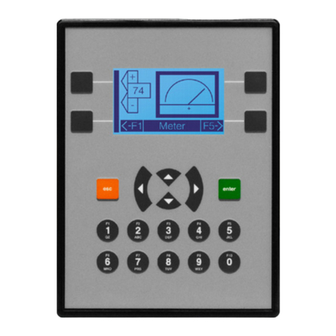
HORNER
HORNER X OCS Series manual
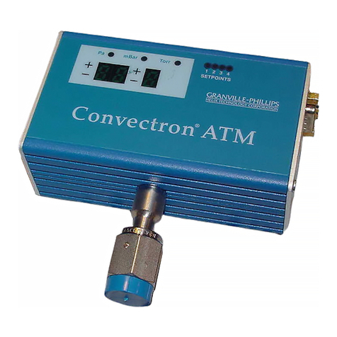
HELIX
HELIX GRANVILLE-PHILLIPS Convectron ATM instruction manual
Moog
Moog 72 Series Installation and operation instruction
Mitsubishi
Mitsubishi MELSEC-A AJ71DN91 user manual
Grosvenor
Grosvenor RM-LUM-M320-IT/A installation guide
Spirax Sarco
Spirax Sarco TD62LM Installation and maintenance instructions

