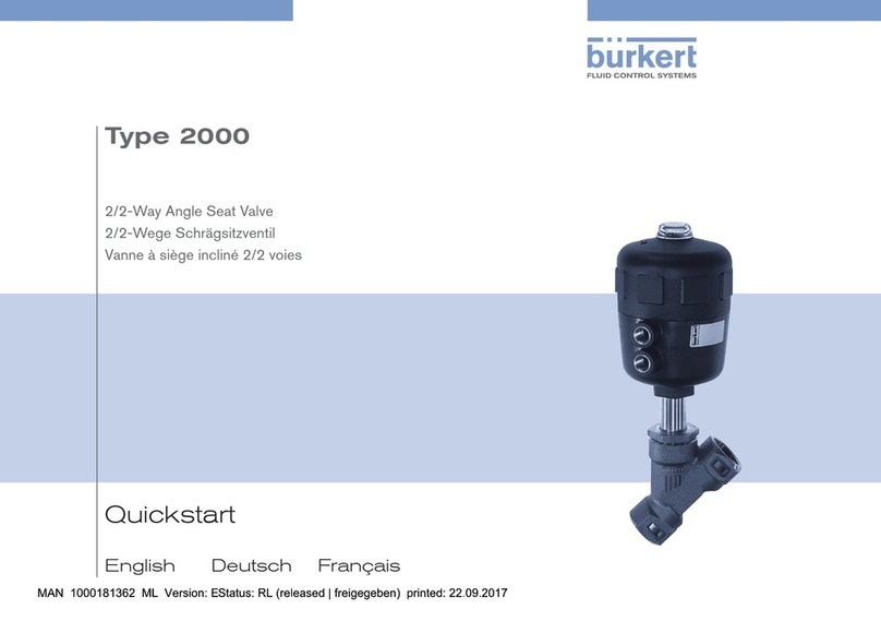
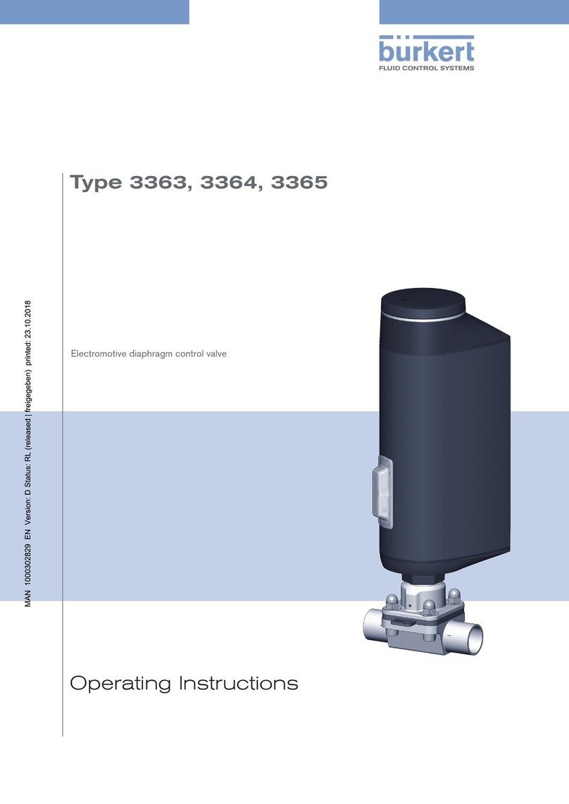
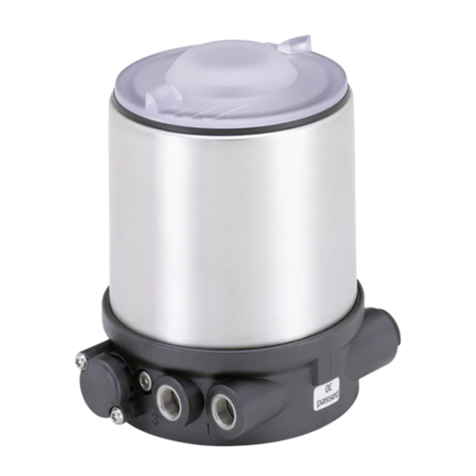
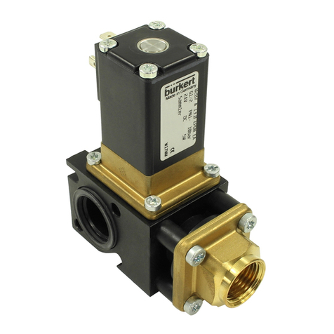
Burkert 2712 Series User manual

Operating Instructions
Bedienungsanleitung
Manuel d‘utilisation
Type 2712
Piston controlled flat-seat valve
Kolbengesteuertes Geradsitzventil
Soupape à tête droite commandée par piston
Actuator sizes 175 mm - 225 mm
Nominal diameters DN 65, DN 80, DN 100
Antriebsgrößen 175 mm - 225 mm
Nennweiten DN 65, DN 80, DN 100
Tailles de mécanisme 175 mm - 225 mm
Diamètre nominal DN 65, DN 80, DN 100

We reserve the right to make technical changes without notice.
Technische Änderungen vorbehalten.
Sous réserve de modifications techniques.
© Bürkert Werke GmbH & Co. KG, 200 - 2017
Operating Instructions 1706/_EU-EN_008 / Original DE

2712 big - 1
CONTENTS
english
Contents of the
overall operating instructions for the
Piston controlled flat-seat valve
Actuator sizes 175 - 225 mm
Nominal diameters DN 65, DN 80, DN 100
GENERAL NOTES............................................................................................................................................................................................................................... 3
Symbols .................................................................................................................................................................................................................................................. 4
Safety information ................................................................................................................................................................................................................... 4
Scope of delivery....................................................................................................................................................................................................................... 4
Warranty conditions.............................................................................................................................................................................................................. 4
TECHNICAL DATA............................................................................................................................................................................................................................. 5
Construction of the control valve ..................................................................................................................................................................... 6
Media ........................................................................................................................................................................................................................................................... 6
COMISSIONING........................................................................................................................................................................................................................................ 7
Installation........................................................................................................................................................................................................................................... 8
MAINTENANCE AND SERVICING........................................................................................................................................................................... 9
Malfunctions................................................................................................................................................................................................................................. 10
Replacing the control cone..................................................................................................................................................................................... 10
Replacement of valve seat ....................................................................................................................................................................................... 12
Spare parts sets for standard valves ....................................................................................................................................................... 13

2 - 2712 big
CONTENTS
english

2712 big - 3
GENERAL NOTES
english
GENERAL
NOTES
Symbols
..................................................................................................................................................................................................................................................
4
Safety notes
......................................................................................................................................................................................................................................
4
Scope of delivery
.......................................................................................................................................................................................................................
4
Warranty conditions
..............................................................................................................................................................................................................
4

4-2712 big
GENERALNOTES
hsilgne
Warranty conditions
This document contains no warranty statements. In this connection we refer to our general sales and
business conditions. A prerequisite for validity of the warranty is use of the device as intended with
observance of the specified conditions of use.
ATTENTION!
The warranty covers only faultless condition of the valveType 2712 with pneumatic
actuator and theTopControl.No liability will be accepted for consequential damage of
any kind that may arise from failure or malfunctioning of the device.
Scope of delivery
Immediately after receipt of a shipment, make sure that the contents are undamaged and match the
scope of delivery stated on the packing slip.
If there are discrepancies, please contact immediately our customer service:
Bürkert Fluid Control Systems
Sales Center
Christian-Bürkert-Str.13-17
D-76453Ingelfingen
Tel.:+49 (0) 7940 - 10 91 111
Fax:+49 (0) 7940 - 10 91 448
E-Mail:info@de.buerkert.com
Symbols
The following symbols are used in these operating instructions:
marks a work step thet you must carry out.
ATTENTION!
marks notes on whose non-observance your health or the functioning of the device will
beendangered.
NOTE
marksimportant additional information, tipsand recommendations.
Please observe the notes in these operating instructions together with the conditions of use and permitted
data that are specified in the data sheets for the pneumatically actuated valve and for the Top
Control
, in
order that the device will function perfectly and remain operable for a long time:
•Keep to standard engineering rules in planning the use of and operating the device!
•Installation and maintenance work are only allowed by specialist personnel using suitable tools!
•Observe the current regulations on accident prevention and safety for electrical devices during
operation and maintenance of the device!
•Switch off the supply voltage in all cases before intervening in the system!
•Note that in systems under pressure, piping and valves may not be loosened!
•Take suitable precautions to prevent inadvertent operation or damage by unauthorized action!
•Make sure that after an interruption to the electrical or pneumatic supply, the process starts up again in
awell-defined, controlled manner!
•Read the safety notes for the electrical part in the operating instructions for theTop
Control
.
•On non-observance of these notes and unauthorized interference with the device, we will refuse all
liability and the warranty on device and accessories will become void!
Safety notes

2712 big - 5
TECHNICAL DATA
english
TECHNICAL
DATA
Construction of the control valve
.....................................................................................................................................................................
6
Media
...........................................................................................................................................................................................................................................................
6

6 - 2712 big
TECHNICAL DATA
english
Liquid and gaseous media are suitable that do not attack the housing and seal materials.
Control medium:instrument air, Class 3 to DIN ISO 8573-1
Construction of the control valve
Media
NOTE
Theapproved operating pressuresand mediatemperatures are tobe takenfrom the data
sheet or rating plate.With regard to the permissible seat leakage rate, the values specified
in DIN EN 1349 are complied with, whereby for the steel/steel seal, leakage class IV
applies, and for the PTFE/steel seal, leakage class VI applies.
2/2-way piston controlled valve with control cone andY-housing.
Controlfunction A
(closed by spring force in rest position)
Controlfunction B
(openin rest position)
Actuatormaterial: PA(polyamide)
Housingmaterial: stainless steel 316L
Seal materials: steel/steel (1.4571) or PTFE/steel

2712 big - 7
COMMISSIONING
english
COMMISSIONING
Installation of the valve
.........................................................................................................................................................................................................
8

8 - 2712 big
COMMISSIONING
english
Procedure:
1. Remove the electrical and pneumatic supplies from the
Top
Control
.
2. Pulloff the pneumatichose betweenTop
Control
and actuator
at the control port of the latter.
3.
Control function A:
Pressurize the lower control port of the actuator with
compressed air (6 bar), so that the control cone is lifted from
the valve seat and is not damaged.
Control function B:
With control function B, no compressed air must be applied
for this purpose.
4. Remove the actuator in the open valve position by
unscrewingthe threaded nipple(SW70)from the housing.
Installation of the valve
NOTE
Forapplications in aggressive media, werecommaend attachingall free pneumatic
connections to a pneumatic hose whose other end lies in a neutral atmosphere.
DN 65 80 100
Tightening torque
[Nm] 100 ± 5 120 ± 5 150 ± 5
Tightening torques for the threaded nipple (SW70)
ATTENTION!
Do
not
loosen the screw (SW65) above the
threadednipple!
screw
(SW65)
threadednipple
(SW70)
5. Before reinstalling the actuator (in the open valve position), grease the nipple thread with
stainlesssteel lubricant, e.g. Klüberpaste UH196-402 fromMessrs. Klüber andreplace
thegraphite seal.
6. After tightening the threadednipple (observe torque),the actuatorcan be alignedas required.
Forthis purpose,unscrew the screw(SW65) abovethe threaded nipple ca. ahalf-turn andbring the
actuator into the desired position.
Then retighten the screw with a torque of 100 ± 5 Nm.
ATTENTION!
For special applications such as for oxygen and analysis, use only the approved
lubricants.
Installationin anyorientation, butpreferably withthe actuatorabove.
Observe the direction of flow: with control valves the general rule is: inlet under seat!
Cleanpipingfrom contamination!
Before attaching the valve housing, make sure the piping is aligned!
If the housing is to be welded on, make absolutely sure that the drive unit is removed beforehand.
ATTENTION!
During this operation, the valve must also be in the open position.
Top
Control
actuator
housing
lower
control port

2712 big - 9
MAINTENANCE AND SERVICING
english
MAINTENANCE AND
SERVICING
Malfunctions
.................................................................................................................................................................................................................................
10
Replacing the control cone
.....................................................................................................................................................................................
10
Replacement of valve seat
.......................................................................................................................................................................................
12
Spare parts sets
......................................................................................................................................................................................................................
13

10 -2712 big
MAINTENANCE AND SERVICING
hsilgne
Possiblemalfunctions concerning theactuator arelisted in the operatinginstructionsfortheTop
Control
.
Replacing the control cone
Malfunctions
Replacing the control cone:
Knock out the dowel pin with a suitable driver.
DriverdiameterØ 8 mm
Pull off the control cone with the aid of two metal strips of equal
height that are clamped to the left and right of the spindle between
the control cone and the threaded nipple of the actuator.To pull off
the control cone, apply compressed air (approx. 6 bar) to the lower
control connection of the actuator.
Place the new control cone onto the end of the spindle.
Align the bores to each other.
On the fluidic side, the control cone can be replaced in case of wear or damage. For this purpose, the
actuator must be disassembled from the housing.
ATTENTION!
Do not damage the sealing surface or the control
contour!
ATTENTION!
Do
not
loosenthe screw(SW65) above thethreaded nipple!
dowel pin control
cone
ATTENTION!
Repairs to the actuator may only be carried out in the factory. Contact your Bürkert
branchor ourCustomer Servicedirectly:
Bürkert Fluid Control Systems
Sales Center
Christian-Bürkert-Str.13-17
D-76453Ingelfingen
Tel.:+49 (0) 7940 - 10 91 111
Fax:+49 (0) 7940 - 10 91 448
E-Mail:info@de.buerkert.com
Disassembly
Remove the electrical andpneumatic supplies fromtheTop
Control
.
Pull off the pneumatic hose between Top
Control
and actuator at the
control port of the latter.
ControlfunctionA:
Pressurize the lower control port of the actuator with compressed
air (6 bar), so that the control cone is liftet from the valve seat and
isnot damaged.
ControlfunctionB:
With control function B, no compressed air must be applied for this
purpose.
Remove the actuator in the open valve position by unscrewing the
threadednipple (SW70) fromthehousing.
screw
(SW65)
threadednipple
(SW70)

2712 big - 11
MAINTENANCE AND SERVICING
english
Support the control cone at ists cylindrical part with the aid of a V-block or the like.
Place the dowel pin in postion and carefully knock in with a hammer.
Bring the dowel pin into a central position relative to the spindle axis (knock it in up to the end of the
recess).
Before reinstalling the actuator (in the open valve position), grease the nipple thread with stainless
steellubricant, e.g. Klüberpaste UH1 96-402from Messrs. Klüber and replacethe graphiteseal.
Assembly
Aftertightening the threadednipple (SW70) (observetorque), the actuatorcan be alignedas required.
Forthis purpose,unscrew the screw(SW65) abovethe threaded nipple ca. ahalf-turn andbring the
actuator into the desired position.
Then retighten the screw with a torque of 100 ± 5 Nm an.
ATTENTION!
For special applications such as for oxygen and analysis, use only the approved
lubricants.
ATTENTION!
During this operation, the valve must also be in the open position.

12 - 2712 big
MAINTENANCE AND SERVICING
english
Replacement of valve seat
To replace the valve seat, the actuator must be disassembled from the housing.For disassembly and
assembly, see "Replacing the control cone".
Tightening torques for seat assembly
Unscrew the old housing seat using the assembly tool and a
spanner.
Cleanthread and sealing surface inthe housingwith compressed
air.
Select a tool insert and screw it into the assembly tool.
Push the new seat onto the assembly tool, grease the thread with
stainlesssteel lubricant, e.g. Klüberpaste UH196-402 from
Messrs.Klüber.
Place the attached seat by hand into the housing thread and
screw it in.
Tighten the seat with a torque wrench to the torque specified.
DN Torque
[Nm]
65 150+10
80 180+10
100 220+10
Seat assembly tools
Housing DN Order no.
15 652 604
20 652 605
25 652 606
32 652 607
40 652 608
50 652 609
assembly tool
tool insert
(to match the nominal
diameter of seat)
valve seat
ATTENTION!
For special applications such as for oxygen and
analysis, use only the approved lubricants.
NOTE
On installing a valve seat with a different nominal
diameter, the order number for the valve changes!

2712 big - 13
MAINTENANCE AND SERVICING
english
Spare parts sets for standard valves
A control cone set, a control fittings set and a set of seals (packed gland) are available as spares.To
disassemble the actuator fromt he housing or reassemble it, proceed as under installation.
NOTE
Beforedisassembling or opening the device,
always
interrupt the supply of medium and
release the pressure in the piping system.
Spare parts sets for special versions are available on
request (e.g. oxygen or analysis versions, etc.)
actuator
threaded nipple SW 70
screw SW 65
control cone set
SET 6
set of seals
(packed gland)
SET 5
control fittings set
SET 6
NOTE

14 - 2712 big
MAINTENANCE AND SERVICING
hsilgne
Control cone set
Valve seat set
DN
housing
DN
seat
Actuator
size
Steel/Steel PTFE/steel
Order no. Order no.
65 40 Ø175 155 625 155 637
65 50 Ø175 155 627 155 639
65 65 Ø175 155 630 155 642
80 50 Ø225 155 628 155 640
80 65 Ø225 155 631 155 643
80 80 Ø225 155 633 155 645
100 65 Ø225 155 632 155 644
100 80 Ø225 155 634 155 646
100 100 Ø225 155.635 155 647
Contains:
Control cone, dowel pin, graphite seal
Set of seals
(packed gland)
DN housing Order no.
65 155 483
80 155 484
100 155 485
Contains:
packed gland module, housing seals
NOTE
Valve seat sets are available on request, please contact your
DN DN
Housing Seat Order no.
65 40 262 202
65 50 262 203
65 65 262 204
80 50 262 205
80 65 262 206
80 80 262 207
100 65 262 208
100 80 262 209
100 100 262 210
Contains: Valve seat, O-ring,
graphite seal

2712 big - 15
INHALT
deutsch
Inhaltsverzeichnis der
Gesamtbedienungsanleitung des
kolbengesteuerten Geradsitzregelventils
mit Antriebsgrößen 175 mm und 225 mm
und Nennweiten DN 65, DN 80, DN 100
ALLGEMEINE HINWEISE
....................................................................................................................................................................................................
17
Darstellungsmittel
................................................................................................................................................................................................................
18
Sicherheitshinweise
..........................................................................................................................................................................................................
18
Lieferumfang
..................................................................................................................................................................................................................................
18
Garantiebestimmungen
...............................................................................................................................................................................................
18
TECHNISCHE DATEN
..............................................................................................................................................................................................................
19
Aufbau des Regelventils
.............................................................................................................................................................................................
20
Medien
.....................................................................................................................................................................................................................................................
20
INBETRIEBNAHME
.......................................................................................................................................................................................................................
21
Einbau
....................................................................................................................................................................................................................................................
22
INSTANDHALTUNG UND WARTUNG
...........................................................................................................................................................
23
Störungen
........................................................................................................................................................................................................................................
24
Austausch des Regelkegels
....................................................................................................................................................................................
24
Austausch des Ventilsitzes
.....................................................................................................................................................................................
26
Ersatzteilsätze für Standardventile
............................................................................................................................................................
27

16 - 2712 big
INHALT
deutsch

2712 big - 17
ALLGEMEINE HINWEISE
deutsch
ALLGEMEINE
HINWEISE
Darstellungsmittel
................................................................................................................................................................................................................
18
Sicherheitshinweise
............................................................................................................................................................................................................
18
Lieferumfang
................................................................................................................................................................................................................................
18
Garantiebestimmungen
...............................................................................................................................................................................................
18

hcstued
18 - 2712 big
ALLGEMEINE HINWEISE
Garantiebestimmungen
Diese Druckschrift enthält keine Garantiezusagen.Wir verweisen hierzu auf unsere allgemeinenVerkaufs-
undGeschäftsbedingungen.Voraussetzung für dieGarantie ist derbestimmungsgemäße Gebrauch des
Gerätesunter Beachtungder spezifizierten Einsatzbedingungen.
ACHTUNG!
DieGewährleistungerstrecktsich nuraufdieFehlerfreiheitdes VentilsTyp2712mitpneuma-
tischemAntriebunddesTop
Control
.EswirdjedochkeineHaftungübernommenfürFolge-
schädenjeglicher Art,diedurchAusfalloderFehlfunktion desGerätesentstehenkönnten.
Lieferumfang
Überzeugen Sie sich unmittelbar nach Erhalt der Sendung, daß der Inhalt nicht beschädigt ist und mit
demauf dembeigelegten Packzettelangegebenen Lieferumfangübereinstimmt.
Bei Unstimmigkeiten wenden Sie sich bitte umgehend an unseren Kundenservice:
BürkertFluid Control Systems
Sales Center
Christian-Bürkert-Str.13-17
D-76453Ingelfingen
Tel.:+49 (0) 7940 - 10 91 111
Fax:+49 (0) 7940 - 10 91 448
E-Mail:[email protected]uerkert.com
Darstellungsmittel
Indieser Betriebsanleitung werdenfolgende Darstellungsmittel verwendet:
markiert einen Arbeitsschritt, den Sie ausführen müssen
ACHTUNG!
kennzeichnet Hinweise, bei deren Nichtbeachtung Ihre Gesundheit oder die Funktionsfä-
higkeit des Gerätes gefährdet ist
HINWEIS
kennzeichnet wichtige Zusatzinformationen,Tipps und Empfehlungen
Bitte beachten Sie die Hinweise dieser Betriebsanleitung sowie die Einsatzbedingungen und zulässigen
Daten, die in den Datenblättern desVentils mit pneumatischem Antrieb und desTop
Control
spezifiziert
sind, damit das Gerät einwandfrei funktioniert und lange einsatzfähig bleibt:
•Halten Sie sich bei der Einsatzplanung und dem Betrieb des Gerätes an die allgemeinen Regeln der
Technik!
•InstallationundWartungsarbeitendürfennurdurchFachpersonalundmitgeeignetemWerkzeugerfolgen!
•BeachtenSie diegeltenden Unfallverhütungs-und Sicherheitsbestimmungenfür elektrischeGeräte
währenddes Betriebesund derWartung desGerätes!
•Schalten Sie vor Eingriffen in das System in jedem Fall die Spannung ab!
•BeachtenSie,daßinSystemen,dieunterDruckstehen,Leitungen undVentilenichtgelöstwerdendürfen!
•Treffen Sie geeignete Maßnahmen, um unbeabsichtigtes Betätigen oder unzulässige Beeinträchtigung
auszuschließen!
•GewährleistenSienach einer UnterbrechungderelektrischenoderpneumatischenVersorgungeinen
definierten und kontrolliertenWiederanlauf des Prozesses!
•EntnehmenSie dieSicherheitshinweisezum elektrischenTeil derBedienungsanleitungdesTop
Control
•Bei Nichtbeachtung dieser Hinweise und unzulässigen Eingriffen in das Gerät entfällt jegliche Haftung
unsererseits, ebenso erlischt die Garantie auf Geräte und Zubehörteile!
Sicherheitshinweise
Other manuals for 2712 Series
1
Table of contents
Languages:
Other Burkert Control Unit manuals

Burkert
Burkert 5281 User manual

Burkert
Burkert 2030 User manual

Burkert
Burkert EPS 21 ATEX 1 234 X User manual

Burkert
Burkert 6144 User manual

Burkert
Burkert 6712 User manual

Burkert
Burkert 3323 User manual

Burkert
Burkert 2060 Guide

Burkert
Burkert 1134 User manual

Burkert
Burkert 5420 User manual

Burkert
Burkert 2064 User manual

Burkert
Burkert 3233 User manual

Burkert
Burkert 8695 User manual

Burkert
Burkert 0470 User manual

Burkert
Burkert 6013 User manual

Burkert
Burkert 6213 EV User manual

Burkert
Burkert 6240 User manual

Burkert
Burkert 2103 Series User manual

Burkert
Burkert 6516 User manual

Burkert
Burkert 6516 User manual

Burkert
Burkert 6027 User manual