Boge airtelligence provis 3 User manual

Operating instructions
Master
compressor control
airtelligence provis 3


BOGE compressor control airtelligence provis 3 Page I
Operating instructions
for the master
compressor control
airtelligence provis 3
Software version V01.00.00.00
BOGE KOMPRESSOREN
Postfach 10 07 13
33507 Bielefeld
Otto-Boge-Straße 1-7
33739 Bielefeld
Fon: +49 5206 601-0
Fax: +49 5206 601-200
Mail: [email protected]
Net: www.boge.com
Issue : 05 / 2020
No. 596.1551.01
Nominal price : € 5,00


BOGE compressor control airtelligence provis 3 Page III
Index
Index
Part 1:
General 1.1 Who are these operating instructions intended for?.................. 1
1.2 Contents of these operating instructions .................................... 1
1.3 Additional important documents .................................................. 2
1.4 Orientation aid for reading these instructions............................. 2
Symbols and typographic features ................................................... 3
Design of warning signs.................................................................... 4
Part 2:
Safety 2.1 Basic information on safety........................................................... 5
Prior to commissioning and operation .............................................. 5
Intended use..................................................................................... 5
Reasonably foreseeable misuse....................................................... 5
Modifications to the product.............................................................. 5
2.2 Special safety notes....................................................................... 5
Transport .......................................................................................... 5
Switch cabinet................................................................................... 6
Touch panel...................................................................................... 6
Network............................................................................................. 6
Change of settings............................................................................ 7
Data backup...................................................................................... 7
2.3 Owner and personnel..................................................................... 7
Personnel requirements.................................................................... 7
Obligations of the operator ............................................................... 8
Obligations of the personnel............................................................. 8
Part 3:
Assembly and connecti-
on
3.1 Installation of the control............................................................... 9
Assembling the switch cabinet.......................................................... 9
Check assembly ............................................................................. 10
3.2 Connecting the control ................................................................ 11
Establishing the electrical connection............................................. 11
Connect the cables for communication in the control cabinet ........ 13
Using external interfaces................................................................ 15
Part 4:
Basic knowledge of con-
trol
4.1 Principle of the master control.................................................... 17
Tasks of the master control in compressed airnets........................ 17
4.2 User levels, rights and functions................................................ 18

Index
Page IV BOGE compressor control airtelligence provis 3
4.3 Operation....................................................................................... 19
Handling by finger or PC mouse..................................................... 19
Operating elements and input functions ......................................... 20
4.4 Symbols......................................................................................... 23
General symbols for components................................................... 23
Special symbols for components - compressor.............................. 23
Special symbols for components - receiver.................................... 24
Special symbols for components - equipment................................ 25
Special symbols for accessory values analog/digital inputs
and outputs..................................................................................... 25
Symbols for basic operating ability ................................................. 26
4.5 Navigation through the views...................................................... 28
Navigation structure........................................................................ 28
Part 5:
Use of the control 5.1 Compressed airnet overview....................................................... 35
5.2 Compressed airnet view .............................................................. 36
Status display: List representation.................................................. 37
Status display: DIN representation ................................................. 37
Status display: 2D representation................................................... 38
Status display: 3D representation................................................... 38
Change arrangement of components in DIN and
2D representation ........................................................................... 39
Calendar display............................................................................. 41
Event display .................................................................................. 50
Progress display ............................................................................. 51
Settings for the compressed airnet................................................. 55
5.3 Component detail view................................................................. 56
Component detail view - compressor ............................................. 57
Component detail view - receiver ................................................... 58
Component detail view- equipment ................................................ 59
5.4 General system settings .............................................................. 61
User administration......................................................................... 62
System settings .............................................................................. 64
Compressed airnet configuration.................................................... 66
Part 6:
Troubleshooting 6.1 Events / message types ............................................................... 69
Process events / messages............................................................ 69
Part 7:
Service, dismantling,
disposal
7.1 Service........................................................................................... 73
Cleaning the display ....................................................................... 73
Software updates............................................................................ 73
7.2 Dismantling / Disassembly .......................................................... 73
7.3 Disposal......................................................................................... 74

BOGE compressor control airtelligence provis 3 Page V
Index
Part 8:
Annex 8.1 Technical data............................................................................... 75
8.2 Housing dimensions and component overview........................ 76
External dimensions and components............................................ 76
Internal components....................................................................... 77
Status LEDs of the control.............................................................. 78


BOGE compressor control airtelligence provis 3 Page 1
General 1.1 Who are these operating instructions intended for?
Part 1: General 1.1 Who are these operating instructions intended
for?
These operating instructions are aimed at BOGE end customers who want to
control the compressed air production of several compressors, organized in
one or several compressed airnets, by means of the master compressor con-
trol airtelligence provis 3.
Apart from reading these operating instructions, the following prerequisites
and previous technical knowledge on the part of the user are essential for the
correct operation of the control:
– comprehensive technical knowledge of the connected compressors
– knowledge of the operating instructions of these compressors
– classification as qualified or appropriately trained personnel with technical
background knowledge in compressed air technology (see also
„Personnel requirements“, page 7)
1.2 Contents of these operating instructions
The operating instructions exclusively deal with installation, functioning, oper-
ation and setting of the airtelligence provis 3.
The following contents and descriptions of activities do not form part of these
operating instructions:
– all safety-relevant information as to the individual compressors, they form
part of the compressor operating instructions.
– anyinformationas to controls whicharedirectlyinstalled on theindividually
connected compressors (slave controls).
– any work, e.g. repairs on the control or installation of updates.
– any work on compressors and equipment (e.g. installation, commissioning
or service).
– description of the complete set-up/installation of compressed airnets or
individual compressors within the master control (specially trained BOGE
service personnel only).
Any of the above mentioned work may only be carried out by authorized and
qualified personnel, qualified electricians or BOGE service personnel.
BOGE recommends to have control(s), compressors and equipment set up
and commissioned by BOGE service personnel. Make sure that any servicing
or repair work on the control is also performed by BOGE service personnel.
If you have any questions as to the product, please contact the Technical
Support by calling:
Phone: +49 5206 601-140
If you require service personnel, please contact BOGE Service by calling:
Phone: +49 5206 601-100

General 1.3 Additional important documents
Page 2 BOGE compressor control airtelligence provis 3
1.3 Additional important documents
For any work not described in these operating instructions the following docu-
ments and specifications are required:
– operating instructions of the compressors,
– operating instructions of the connected equipment,
– operating instructions of the subordinate (slave) control(s).
Please observe the specific safety information provided in these documents!
Below you will find directions how to read these instructions and information
as to the design of the warning signs used in these operating instructions.
1.4 Orientation aid for reading these instructions
In order to easily familiarize with the compressor control, the layout of the
operating instructions is intended to give you better orientation and support.

BOGE compressor control airtelligence provis 3 Page 3
General 1.4 Orientation aid for reading these instructions
Symbols and typo-
graphic features The following table provides an overview of all symbols and typographic fea-
tures meant to facilitate the reading:
Tab. 1.1: Overview of the means of design for easier reading of these operat-
ing instructions
Symbol Meaning
Tips and further notes for optimum han-
dling
Particularlyimportanttipsandnoteshelpingto
optimally operate the control are marked with
a frame and the illustrated symbol.
Thesettings describedinthissectioncanonly
be made after login with user name and pass-
word, see also „User levels, rights and func-
tions“, page 18.
– Information 1
– Information 2
– Information 3
Listing
For a clear and understandable presentation
some important information are listed up.
●Action step Instructions I
Instructions with one action step only are in-
dicated with the symbol shown.
1. Action step 1
2. Action step 2
3. Action step 3
Instructions II
Instructions with several action steps are
numbered and must be carried out in the
specified sequence.
Feedback for action step Feedback
The result to be expected after an action step
is indicated with the arrow shown.
(1)
(2)
(3)
Figures and illustrations
For a better understanding, illustrations of the
user interface of the touch panel are possibly
divided by frames into several image areas.
The individual image areas are numbered.
General 1.4 Orientation aid for reading these instructions
Page 4 BOGE compressor control airtelligence provis 3
Design of warning signs The warning signs and notes in these instructions are to indicate dangers that
may occur during execution of specific actions. Apart from this, they point out
how a danger situation can be prevented. Warning signs are designed accord-
ing to a fixed structure, described in the following.
Signal words
The following signal words are used:
General warning sign
The following general warning sign is used in this document:
Warning sign design
Warning signs are a combination of signal words, warning signs and informa-
tion text and structured as follows:
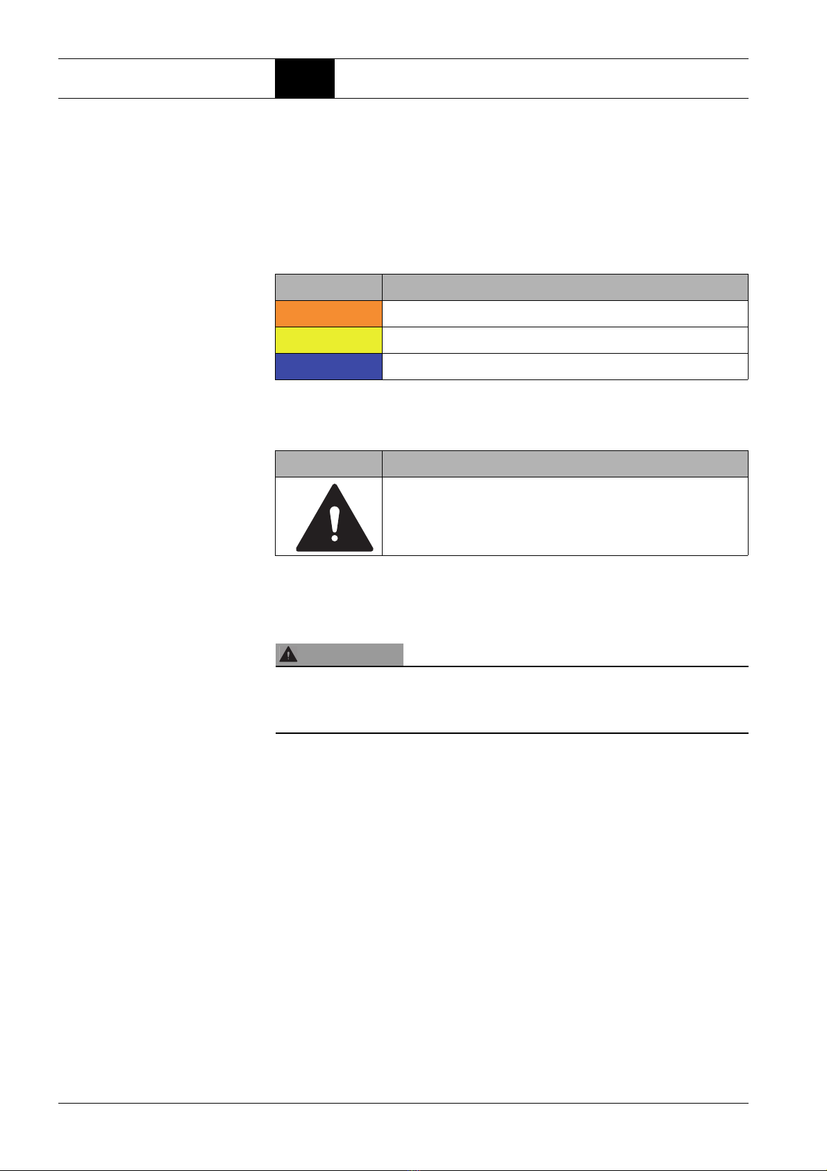
Signal word Meaning
WARNING Warns of dangers that can possibly lead to serious or fatal injuries.
CAUTION Warns of damage to property and loss of data.
NOTE Warns of malfunctions within the operating process/communication.
Warning sign Meaning
Warns of a hazardous area.
SIGNAL WORD
Kind of danger
Source of danger and consequences if the warning is not observed.
How to avoid any danger.

BOGE compressor control airtelligence provis 3 Page 5
Safety 2.1 Basic information on safety
Part 2: Safety 2.1 Basic information on safety
Prior to commissioning
and operation Prior to commissioning and operation of the airtelligence provis 3 control the
following points must be observed:
– These operating instructions must be read completely priorto commission-
ing/operation of the control.
– These operating instructions must always be available at the place of oper-
ation of the control.
– Changes of settings on controls may only be carried out by authorized
qualified personnel, see also „Personnel requirements“, page 7.
– The control is installed in a separate switch cabinet. Work on the control,
for which the switch cabinet must be opened, may only be carried out by
authorized and qualified electricians, see also „Personnel requirements “.
– Prior to first commissioning, check control for visible signs of transport
damage.
– Damage to the control that could impair the safety of machine operation
must be rectified immediately.
Intended use The control serves solely for the correct operation of one or several com-
pressed airnets, consisting of one or several BOGE compressors or compres-
sors of other manufacturers and connected equipment, if applicable. It is
designed for stationary indoor use in manufacturing and industrial areas.
BOGE controls, especially the focus control 2.0, are designed and developed
for use in closed industrial networks (technical network).
Reasonably foreseeable
misuse Non-observance of the application limits (see „8.1 Technical data“, page 75)
is considered unintended use, poses a risk to the operational safety of the con-
trol and can endanger the compressed air supply.
Furthermore, considerable material damage and personal injury may be the
result.
Modifications to the
product Improper or unauthorized operation of the control can endanger the opera-
tional safety and damage connected devices or machines. It is not permitted
to perform any modifications, extensions or conversions to the control, like-
wise no repairs may be carried out. If a component of the control is defective,
contact BOGE service and coordinate any further proceedings.
2.2 Special safety notes
Transport – During transport, removal, relocation or return shipments the switch cabi-
net must be secured against slipping or falling down by means of suitable
measures. Internal transport is only permitted if the switch cabinet is ade-
quately secured against tilting and falling over.
– The instructions for handling the packaged products as well as humidity,
shock, tipping and temperature indicators on the packaging must be
observed.
– The control must be transportedin a horizontal position. The maximum per-
missible deviation from the horizontal is 15°.
Safety 2.2 Special safety notes
Page 6 BOGE compressor control airtelligence provis 3
– Only suitable and approved lifting and transport tools may be used for
unloading and transport.
– Never climb onto control unit or packaging.
– Protect surfaces and frame from damage.
– During transport or intermediate storage, ensure that the surfaces are
weather-protected, dry, clean and protected from external influences.
– The breaking load classes must be observed. Place insensitive parts at the
bottom.
– Observe any information on humidity and temperature range during trans-
port (see „8.1 Technical data“, page 75).
Switch cabinet The control is installed in a separate switch cabinet.
The operating unit of the control, the touch panel, is installed in the front of the
switch cabinet.
– The control may only be operated by means of the touch panel when the
switch cabinet is closed
– Never open switch cabinet during operation.
– If necessary, switch cabinet to be opened by authorized and qualified elec-
tricians only.
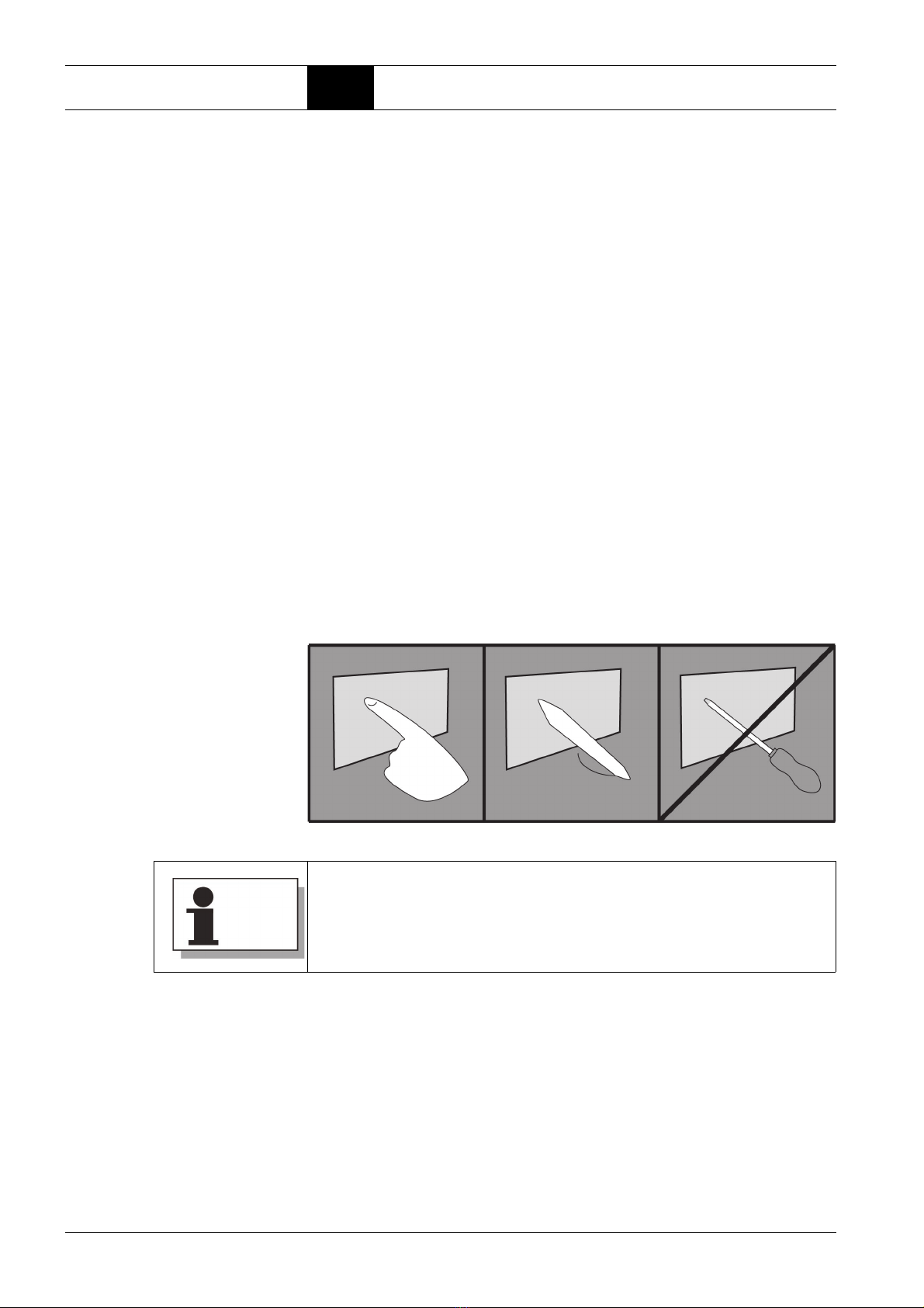
Touch panel – No pointed or sharp-edged objects may be used when operating the touch
panel. They can damage the surface of the touch panel. Only operate the
touch panel with your fingers or a suitable input pen with a plastic tip.
Fig. 2.1: Operate touch panel properly
Network The control and configuration protocols do not provide authentication mecha-
nisms. Furthermore, large amounts of network traffic can lead to an impair-
ment of the controlcommunication. BOGEthereforestronglyrecommendsthe
use of the controls exclusively in closed networks (technical network).
The network configuration, e.g. the IP address assignment, must be carried
out in coordination with the responsible IT department, which is also respon-
sible for the network in which the control is to be operated. Incorrect settings
(such as repeatedly assigned IP addresses,incorrectgateways,etc.)canalso
lead to interference with other network participants.
Notes on cleaning the display on page 73.

BOGE compressor control airtelligence provis 3 Page 7
Safety 2.3 Owner and personnel
In addition, the specified minimum qualities of the network cables (CAT 6)
must be observed.
Change of settings The control regulates the individual compressed airnets by means of settings
or parameters that can be defined individually. These adjustable values can
therefore be used to change the control behavior of the compressors so that
each net produces compressed air on demand. However, incorrect settings
may also cause faults in the operating process or destruction of components.
– The change of settings / parameters may only be carried out by authorized
specialist personnel with sound knowledge of compressed air technology.
– In cases of doubt please contact BOGE service prior to changing any set-
tings.
Data backup The control is equipped with a Solid State Drive (SSD). All changes made to
adjustable values are automatically stored in this internal memory after being
entered.
To ensure that an originally existing configuration is not lost after a possible
defect of the SSD memory or a change of the settings, it can be transferred to
an external memory for backup using the "Export configuration file" function
(see „Configuration import and export“, page 65).
2.3 Owner and personnel
Personnel requirements Basically only those persons may carry out activities on the control who per-
form their tasks duly and reliably and meet the following requirements:
Trained personnel
Trained personnel are persons who have been instructed in a verifiable and
detailed manner by the owner about their assigned tasks and any potential
risks in this conjunction.
Qualified personnel
Qualified personnel are persons who, due to their professional training, knowl-
edge and experience as well as their awareness of the relevant regulations,
are in a position to carry out the tasks assigned to them and be able to auton-
omously identify any potential hazards and to prevent personal injury or prop-
erty damage.
Qualified electricians
Qualified electricians are persons who, due to their professional training,
knowledge and experience as well as their awareness of the relevant stan-
dards and regulations, are in a position to properly carry out work on electrical
installations, to autonomously identify any potential hazards and to prevent
personal injury or property damage caused by electric current.
Prior to describing any work that requires special knowledge, it is clearly
indicated in these operating instructionswhat qualifications profile a person
must comply with to perform the described tasks.

Safety 2.3 Owner and personnel
Page 8 BOGE compressor control airtelligence provis 3
Personal protective equipment (PPE)
During transport, assembly and maintenance/service work
– protective clothing,
– slip-resistant safety shoes,
– cut and puncture-resistant protective gloves
– protective helmet (for compressor transport and work inside the compres-
sor)
– Safetygoggles(when working onpressurizedcomponents/ on the control
pneumatics)
must be worn.
When operating the control in the compressor room, hearing protection must
also be worn if necessary.
Obligations of the opera-
tor The operator is subject to the statutory obligations for occupational safety and
must be informed about the valid health and safety regulations.
The use of the master control implies that a suitable safety concept has been
developedfor the machines or plants.This includes a hazardand risk analysis
in accordance with the relevant guidelines and standards (e.g. EMC and Low
Voltage Directive) and a test report for the validity of the safety functions.
Furthermore:
– The operator must authorize qualified electricians for any work on the con-
trol cabinet.
– The owner must only provide the key for opening the control cabinet to
qualified electricians who have been authorized by him to perform work on
the control cabinet.
– The owner must authorize specialist staff performing changes to settings/
parameters of the control.
Obligations of the per-
sonnel The personnel is subject to the statutory obligations for occupational safety
and must be informed about the valid health and safety regulations.
Furthermore:
– The personnel must have completely read the operating instructions prior
to commissioning/operation of the control.
– Personnelmust havereadthe operatinginstructions for compressors, their
integrated controls and the equipment in full prior to commissioning/oper-
ating these components.
– The staff must have been authorized based on these instructions for any
work that they may perform depending on their qualification.
BOGE compressor control airtelligence provis 3 Page 9
Assembly and connection 3.1 Installation of the control
Part 3: Assembly and
connection 3.1 Installation of the control
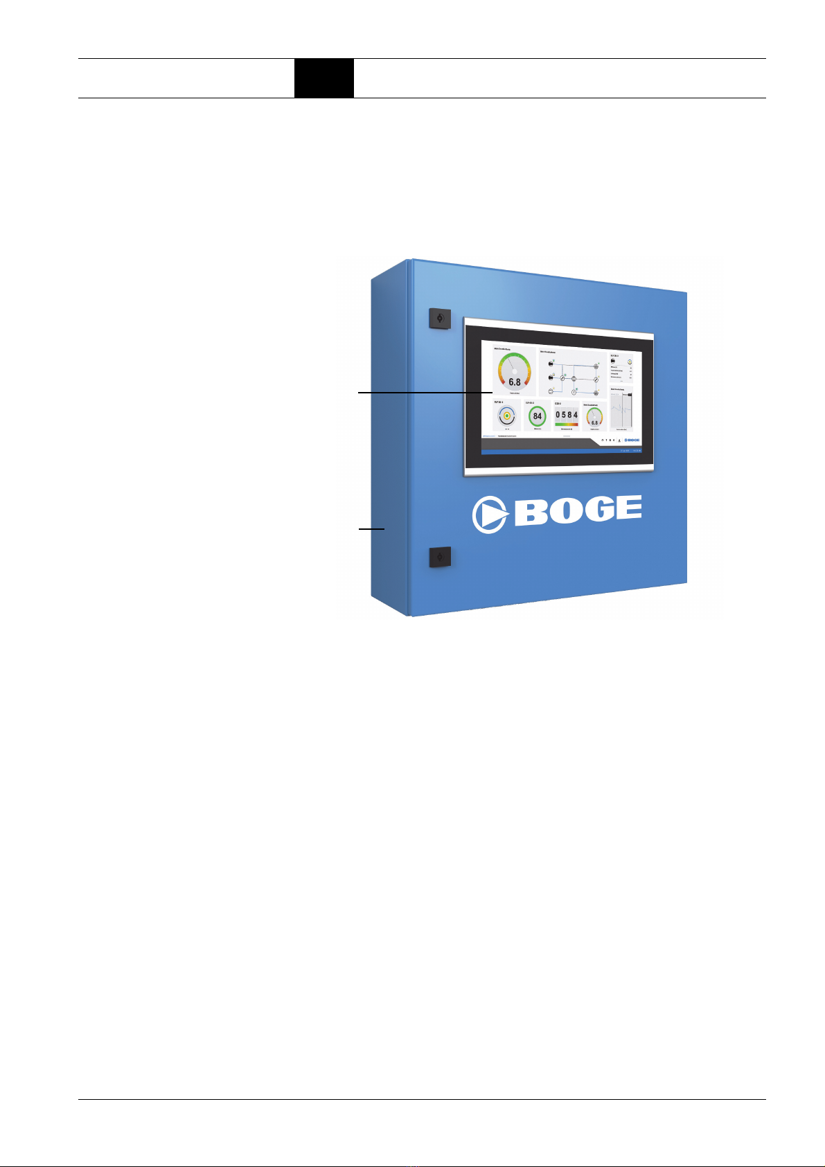
The airtelligence provis 3 is installed in a separate switch cabinet. The oper-
ating unit of the control, the touch panel (1), is located in the front of the switch
cabinet (2).
Fig. 3.1: Switch cabinet with touch panel
After delivery, the switch cabinet must be set up and installed at a suitable
location before the necessary components can be connected and the control
can be put into operation.
Assembling the switch
cabinet Safety instructions prior to assembly
– Ensure that the installation site is free from dirt and moisture.
– Physically separate the switch cabinet from frequency converters and
high-voltage appliances.
– Avoid functional failures that can be caused by heat generation and inter-
ference with adjacent components, by meeting the requirements of EN
61439:
– Ensure that the temperature limits at the place of operation are
observed (see „8.1 Technical data“, page 75).
– Do not place the switch cabinet directly next to heat sources.
– The components are designed for cooling by convection: therefore
avoid heat accumulation and ensure that no openings are covered
(e.g. by surface-mounted cables).
– During assembly, ensure that the bottom side of the control cabinet hous-
ing points downwards (see also „Housing dimensions and component
overview“, page 76). The specified ambient conditions, especially the
ambient temperatures, apply to this alignment only.
(1)
(2)

Assembly and connection 3.1 Installation of the control
Page 10 BOGE compressor control airtelligence provis 3
To assemble the switch cabinet:
1. Mark boreholes on the wall.
2. Drill holes at the marked positions.
3. Insert suitable dowels into the drill holes.
4. Fasten the switch cabinet with suitable screws and washers if necessary.
5. Protect all bores and bare machining points from corrosion.
The switch cabinet is assembled.
Check assembly 1. Check to ensure that the switch cabinet is firmly tightened.
2. Check switch cabinet and components for damages.
3. Ensure that the required assembly clearances have been maintained.
WARNING
Risk of injury due to improper assembly!
The switch cabinet can fall down if not mounted properly. Injuries and dam-
age to property can be the result.
Assembly work may only be carried out by trained personnel.
Carry out assembly with at least two persons.
Follow the instructions in section „ Intended use“, page 5.
Use the fixing material included in the scope of delivery.
Always wear PPE during assembly work.
CAUTION
Risk of property damage due to improper assembly!
If the switch cabinet is exposed to vibrations at its installation location, the
product may be damaged.
Do not install the switch cabinet on vibrating or oscillating supports,
machines and equipment parts.
Ensure that there is sufficient freedom of movement for installation, opera-
tion and service work on the switch cabinet.
BOGE recommends that a circumferential distance of 1 meter to surround-
ing components is maintained.

BOGE compressor control airtelligence provis 3 Page 11
Assembly and connection 3.2 Connecting the control
3.2 Connecting the control
Once the installation of the switch cabinet has been completed, the power sup-
plymust be establishedintheswitchcabinet.Thelinesfor communicationwith
the components to be acquired by the control must also be connected.
Safety instructions prior to establishing the connections
– All work on and in the switch cabinet, including establishing of the connec-
tions and subsequent commissioning, may only be carried out by author-
ized electricians.
– When connecting to the power supply, observe the valid national and inter-
national regulations (e.g. VDE regulations, DIN-EN standards) and the
local safety regulations.
– The electrical equipment of the installation must be designed in accord-
ance with the Low Voltage Directive and the EMC Directive.
Establishing the electri-
cal connection To establish the electrical connection:
1. Ensure that the customer has installed the back-up fuse recommended in
the Technical Data on page 75.
2. Open switch cabinet.
3. Checkthatall componentsare securely seated on the top-hat rails and that
the retaining clips of the components are firmly engaged.
4. Check whether all installed conductive connections are firmly tightened.
5. If necessary, tighten loose connections with a torque screwdriver. Observe
the following torques:
Tab. 3.1: Torques of switch cabinet components
For proper connection and commissioning of the control you need the sup-
plied wiring diagram. The circuit diagram must be kept in a safe place for
later use.
WARNING
Risk of injury from live parts!
When establishing the electrical connection, there is a risk of life-threatening
electric shock when the power supply is connected.
The electrical connection may only be established in a de-energized
state.
Work may only be carried out by authorized qualified electricians.
BMK Designation/Type Torque
-14K1 Panel-PC - airtelligence provis 3 0.89 Nm
-20K1 Industrial Ethernet Switch - FL Switch SFNB 8TX 0,5 Nm ... 0,6 Nm
Assembly and connection 3.2 Connecting the control
Page 12 BOGE compressor control airtelligence provis 3
6. Insert the cable into the switch cabinet through the threaded cable gland.
CAUTION Riskof propertydamages.Insufficientcross-sectionofthecable
wires can lead to malfunctions and overheating of the cable.
Use wires with a minimum cross section of 1.5 mm².
7. Strip the cable and the cable cores according to the required length.
8. Strip wire ends.
9. Fit the individual wires with suitable wire ferrules.
The wires are ready for connection to the terminal strip
-12X0.
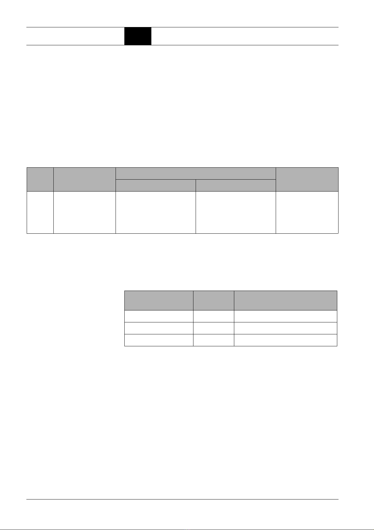
Necessary specifications of the cable wires for connection to terminal
strip -12X0:
Tab. 3.2: Specifications of conducting wires for power supply
In order to connect thewires correctly, the numbers on the terminals of the ter-
minal block must be observed so that the external conductor, neutral conduc-
tor and protective earth can be assigned to the correct connections of the
-12X0 terminal block.
Tab. 3.3: Assignment of terminal block to cable wire
To connect a cable wire to the terminal strip -12X0:
10.Press and hold the orange push button with a special screwdriver for elec-
trical installation.
11.Insert the cable wire into the round opening of the push-in terminal block.
12.Release the push button to fix the wire in the terminal compartment.
The cable wire is connected.
13.Perform the procedure with all 3 wires of the cable according to the assign-
ment in table 4.3.
14.Check all cable wires for tight fitting.
The electrical connection is established.
BMK fixed conductor flexible conductor Stripping length
without ferrule with ferrule
-12X0 0.14 mm² ... 4 mm² 0.14 mm² ... 2.5 mm² without plastic sleeve
0.14 mm² ... 2.5 mm²
with plastic sleeve
0.14 mm² ... 2.5 mm²
8 mm ... 10 mm
Number on terminal
block Designation Explanation
1 L1 Connection for external conductor
2 N Connection for neutral conductor
3 PE Connection for protective earth conductor
Table of contents
Other Boge Control Unit manuals


Popular Control Unit manuals by other brands

VXI Technology
VXI Technology VM1548C user manual

Burkert
Burkert 6650 operating instructions

AMX
AMX AXB-DTMF Plus Specifications

GEM
GEM R690 Installation, operating and maintenance instructions

National Instruments
National Instruments NI PXI-6682 installation guide

Arbor Technology
Arbor Technology EmNANO-i2300 user manual

C&C
C&C Atlas Series Installation, operation and maintenance manual

RJG
RJG Lynx IA1-M-V product manual

Digital Equipment
Digital Equipment Mod-MAC Series Installing and Cabling

INSTEON
INSTEON 2634-222 owner's manual

Drivecon
Drivecon XT Series Service manual

Savant
Savant IP Audio 125 with Savant Music 2.0 Quick reference guide


