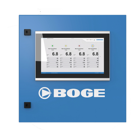
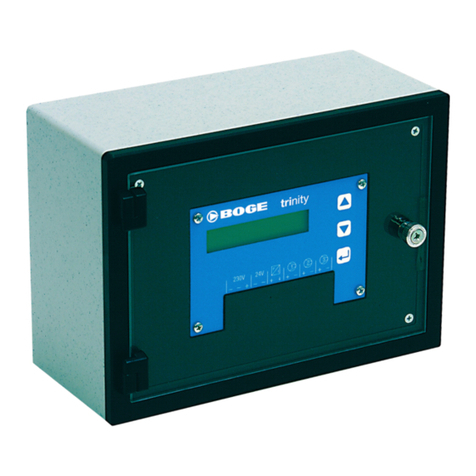
Boge base control User manual

Operating Instructions
base control
for Scroll Compressors


BOGE base control for scroll compressors Page I
Operating Instructions
base control
for Scroll Compressors
BOGE KOMPRESSOREN
Otto Boge GmbH & Co. KG
Postfach 10 07 13
33507 Bielefeld
Otto-Boge-Straße 1-7
33739 Bielefeld
Tel: +49-520-660-10
Fax: +49-520-660-1200
Email: [email protected]
Web: www.boge.com
Version: 11 / 2016
No. 596.1454.18
Nominal price: €5.00


BOGE base control for scroll compressors Page III
Table of Contents
Table of Contents
Part 1:
About these Operating
Instructions
1.1 Who are these Operating Instructions aimed at?........................ 1
1.2 Content of these Instructions........................................................ 1
1.3 Other Important Documents .......................................................... 2
1.4 Guide for Reading........................................................................... 2
Symbols and Typographic Aids ........................................................ 2
Structure of Warning Notices............................................................ 3
Part 2:
Safety
2.1 General Safety Information............................................................ 5
Prior to Commissioning and Operation............................................. 5
Intended Use .................................................................................... 5
Reasonably Foreseeable Misuse ..................................................... 5
2.2 Special Safety Information............................................................. 6
Switch Cabinet.................................................................................. 6
Emergency Stop Function / Main Switch .......................................... 6
Changing Parameters / Settings....................................................... 7
Data Security .................................................................................... 7
Damage to the Control Unit .............................................................. 7
2.3 Operator and Personnel................................................................. 7
Personnel Requirements .................................................................. 7
Obligations of the Operator............................................................... 8
Obligations of Personnel................................................................... 8
Part 3:
Layout and Function
3.1 Operating Principle of the Control ................................................ 9
Basic Tasks of the Control................................................................ 9
Use as a Lower-level Control in the Compressor Network ............... 9
3.2 Layout of the Control Unit ........................................................... 10
LCD Display (1) .............................................................................. 11
"Fault" and "Ready" Indicator Lamps (2 and 3) .............................. 11
Info and Enter Keys (4 and 5)......................................................... 11
On and Off Keys (6 and 7).............................................................. 12

Table of Contents
Page IV BOGE base control for scroll compressors
Part 4:
Display and Operation
4.1 Description of Display Symbols .................................................. 13
4.2 Description of the Displays and Navigation............................... 14
Main Display ................................................................................... 14
Additional Displays ......................................................................... 16
Part 5:
Setting Parameters
5.1 Unlocking Code-protected Parameters ...................................... 19
5.2 Changing Individual Parameters................................................. 20
Parameter Codes............................................................................ 20
Compressor Servicing Interval: Restart the Counter / Change the Start
Value............................................................................................... 20
Motor Servicing Interval: Restart the Counter / Change the Start Value
21
Change Target Pressure Values (pmax and pmin) ........................... 22
Activating / Deactivating the Auto-Restart Function ....................... 23
Activating / Deactivating the External Output Release ................... 25
Performing Leakage Measurement (without code release) ............ 27
Part 6:
Troubleshooting
6.1 Message Types ............................................................................. 31
6.2 Processing Messages .................................................................. 31
6.3 List / Meaning of Message Codes ............................................... 32
6.4 Acknowledging Messages ........................................................... 33
Part 7:
Servicing
7.1 Cleaning the Display .................................................................... 35
7.2 Updating the Software.................................................................. 35

BOGE base control for scroll compressors Page 1
About these Operating Instructions
1.1 Who are these Operating Instructions aimed at?
Part 1: About these Operating Instructions
1.1 Who are these Operating Instructions aimed at?
These operating instructions are aimed at end customers of BOGE who have
purchased a scroll compressor and wish to operate it using the compressor
base control.
In addition to reading these instructions, the user must meet the following pre-
requisites in order to ensure professional operation of the control. S/he must:
– have an understanding of the compressor
– have an understanding of the accompanying operating instructions
– be classified as qualified personnel or trained personnel with technical
background knowledge in the field of compressed air technology (see also
"Personnel Requirements", page 7).
1.2 Content of these Instructions
These operating instructions deal exclusively with the functionality, operation
and parametrization of the base control.
The following content and work descriptions do not form part of these operat-
ing instructions:
– All safety information on the compressor. This is part of the compressor
operating instructions.
– Work such as electrical commissioning or repairs to the control.
– Work on the control that requires the switch cabinet to be opened, for
example installing updates.
– Work on the compressor and its accessories (e.g. installation or commis-
sioning).
The above-mentioned work must only be carried out by an authorized, quali-
fied electrician or BOGE Service personnel.
BOGE recommends having the control, compressor and accessories set up
and commissioned by BOGE Service personnel. Maintenance and repair work
on the control should also be carried out by BOGE Service personnel.
Should you have any questions about this product, please contact
Product Support on:
Telephone: +49-520-660-1140
If you require Service assistance, please contact BOGE Service on:
Telephone: +49-520-660-1100

About these Operating Instructions
1.3 Other Important Documents
Page 2 BOGE base control for scroll compressors
1.3 Other Important Documents
The following documents are required for any work not described in these
operating instructions:
– the compressor operating instructions;
– the operating instructions for the connected accessories.
Pay particular attention to the safety information in this document!
The following pages contain a guide for reading these instructions as well as
information on the design of warning notices.
1.4 Guide for Reading
These operating instructions are designed to help you to operate the compres-
sor control quickly and easily.
Symbols and Typo-
graphic Aids
The following table contains an overview of all the symbols and typographic
aids used to simplify the content:
Symbol Meaning
Setup Mode
In this area, settings can only be
changed if a code has been issued.
Tips and additional information on
optimum operation
Tips and information that help you
to use the control in an optimum
manner are indicated by the symbol
shown.
– Information 1
– Information 2
– Information 3
List
Important information is listed clear-
ly.
●Action Directions for Use I
Directions for use with one action are
indicated by the symbol shown.

BOGE base control for scroll compressors Page 3
About these Operating Instructions
1.4 Guide for Reading
Tab. 1.1: Overview of all design elements that simplify the content of these
instructions
Structure of Warning
Notices
The warning notices in these instructions indicate dangers that may occur
when carrying out certain tasks. They also indicate how a dangerous situation
can be avoided. Warning notices follow a fixed structure which is described
below.
Signal Words
The following signal words are used:
Tab. 1.2: Signal words
1. Action 1
2. Action 2
3. Action 3
Directions for Use II
Directions for use with several actions
are numbered and must be carried out
in the specified sequence.
Result of action Result
The outcome that will follow an ac-
tion is indicated by the arrow shown.
(1)
(2)
(3)
Screenshots
The screenshots of the operating unit
display may be divided into areas.
The individual areas are numbered.
Symbol Meaning
Signal Word Meaning
WARNING Warns of dangers to persons that could lead to serious
injury or death.
CAUTION Warns of property damage and data loss
NOTE Warns of faults in the operating sequence /
communication

About these Operating Instructions
1.4 Guide for Reading
Page 4 BOGE base control for scroll compressors
Warning Signs
The following warning signs are used:
Tab. 1.3: Warning signs
Design of Warning Notices
Warning notices are a combination of signal words, warning signs and infor-
mation. They are structured as follows:
Warning Sign Meaning
Warns of a hazardous area
Warns of life-threatening electrical voltage
SIGNAL WORD
Type of Danger
Source of the danger and consequences if the warning notice is not ob-
served.
How to avoid the danger.

BOGE base control for scroll compressors Page 5
Safety 2.1 General Safety Information
Part 2: Safety 2.1 General Safety Information
Prior to Commissioning
and Operation
The following must be observed prior to commissioning and operation of the
base control:
– These instructions must be read thoroughly and understood before com-
missioning / operating the control.
– These instructions must be available at all times at the place of operation
of the control.
– Changes to parameters and settings may only be carried out by authorized,
qualified personnel, see also "Personnel Requirements".
– Work on the control that requires the switch cabinet to be opened may only
be carried out by an authorized, qualified electrician, see also "Personnel
Requirements".
– Prior to initial commissioning of the control unit, check for visible transport
damage.
– Damage to the control that affects safe operation of the machine must be
rectified immediately.
Intended Use The control is intended exclusively for the correct operation of a BOGE scroll
compressor and its connected accessories.
Reasonably Foreseeable
Misuse
The control is not suitable for use with other types of compressed air genera-
tors or compressors from other manufacturers.

Safety 2.2 Special Safety Information
Page 6 BOGE base control for scroll compressors
2.2 Special Safety Information
Switch Cabinet The control is housed in a switch cabinet.
The control unit of the control can be found at the front of the switch cabinet.
The control may only be operated via the control unit when the switch cabinet
is closed.
Please note that only settings that can be applied via the control unit of the
control may be changed using these operating instructions.
Emergency Stop
Function / Main Switch
The emergency stop function serves to avert or prevent a prevailing emer-
gency situation, where such a situation is the result of conduct by individuals
or an event posing an unexpected danger.
The emergency stop function is provided through the main switch. When the
main switch with emergency stop function is pressed, compressor operation
stops immediately and the switch cabinet and control are no longer live.
Dangerous voltage may still be present on the supply terminals even though
the machine is disconnected from the grid.
The main switch is not located on the control unit of the base control; it is in-
stead in a highly visible location on the front of the scroll compressor housing.
WARNING
Risk of Electric Shock
Live parts are located inside the switch cabinet. There is a risk of electric
shock when the switch cabinet is opened.
Never open the switch cabinet during operation.
Only operate the control when the switch cabinet is closed.
The switch cabinet may only be opened by an authorized and qualified
electrician.
Please note:
– Press the main switch to avoid or prevent an emergency situation.
– In normal operation the Off key should be pressed on the control to prop-
erly shut down the compressor.
– In addition, always press the main switch when carrying out inspections
or work on the compressor or switch cabinet.

BOGE base control for scroll compressors Page 7
Safety 2.3 Operator and Personnel
Changing Parameters /
Settings
The control regulates the compressor using specific parameters / settings.
The individual parameters represent the values that can be used to change
the compressor functions (e.g. switch-on and switch-off pressure) so that the
compressor generates compressed air as required. However, incorrect set-
tings can also lead to operational faults or destruction of the compressor.
Data Security The base control automatically stores all data – e.g. altered settings – in the
non-volatile memory. The saved data are therefore also available in the event
of a power failure.
Damage to the Control
Unit
All keys on the control unit are operated by tapping on them with a finger. Light
tapping on the interface is sufficient to actuate the keys. Do not use any sharp
or abrasive objects when operating the control unit. BOGE accepts no liability
for damage resulting from improper use.
2.3 Operator and Personnel
Personnel Requirements Only individuals who are able to carry out the work correctly and reliably and
who meet the following requirements may perform work on the control:
Trained Personnel
Trained personnel are individuals who have been informed in detail by the
operator of the potential dangers concerning the tasks assigned to them and
for whom this training has been documented.
Qualified Personnel
Qualified personnel are individuals who are able to successfully carry out work
assigned to them, recognize potential dangers independently and avoid injury
to individuals or property due to their professional training, knowledge and
experience as well as their knowledge of the relevant regulations.
CAUTION
Compressor Damage
Changing parameters / operational settings that have an effect on the oper-
ation or function of the compressor may damage or destroy the compres-
sor.
Only authorized, qualified personnel may make changes to parameters
or settings.
If in doubt regarding a change to operational settings, contact BOGE
Service.

Safety 2.3 Operator and Personnel
Page 8 BOGE base control for scroll compressors
Qualified Electricians
Qualified electricians are individuals who are able to successfully carry out
work assigned to them, recognize potential dangers independently and avoid
injury to individuals or property due to their qualifications, knowledge and ex-
perience as well as their knowledge of the relevant regulations.
Obligations of the
Operator
The operator is subject to the legal obligations concerning occupational safety
and must be familiar with the applicable occupational health and safety regu-
lations. In addition:
– The operator must authorize qualified electricians to carry out work on the
switch cabinet.
– The operator may only provide the key to the switch cabinet to a qualified
electrician who is authorized to carry out work on the switch cabinet.
– The operator must authorize qualified personnel to change parameters or
settings on the control.
Obligations of Personnel Personnel are subject to the legal obligations concerning occupational safety
and must be familiar with the applicable occupational health and safety regu-
lations. In addition:
– Personnel must have read these instructions thoroughly before commis-
sioning / operating the control.
– The same applies to the instructions for the compressor and accessories.
– For all work requiring specific qualifications, personnel must be authorized
by the operator to carry out such work in line with these instructions.
Prior to descriptions of work requiring specialist knowledge, the require-
ments that the individual must fulfill in order to be able to carry out the work
described are clearly stated.

BOGE base control for scroll compressors Page 9
Layout and Function 3.1 Operating Principle of the Control
Part 3: Layout and Function
3.1 Operating Principle of the Control
The compressor control is the central control element of the compressor sys-
tem.
The compressor control with switch cabinet is integrated in the compressor
housing and connected directly to the compressor. This means that it is ready
for operation as soon as the compressor is connected to the power supply.
Basic Tasks of the
Control
The first essential task carried out by the control is the monitoring of all com-
pressor system functions. Information on compressor operation can be called
up and checked on the control display. This includes data on the current oper-
ating status of the compressor or servicing intervals (see Part 4: Display and
Operation, page 13 ff.).
The second essential task carried out by the control is the efficient regulation
of the compressor for tailored use. To do this, compressor parameters can
be set via the control. These are required for the compressor to generate com-
pressed air according to individual requirements. This includes parameters
for setting the pressure to be generated (see Part 5: Setting Parameters,
page 19 ff.).
Use as a Lower-level
Control in the Compres-
sor Network
The BOGE base control can be connected to the master control of
a compressor network via a Modbus interface module. The lower-level
control then operates according to the instructions of the master control.
It must also be parameterized to suit the master control.

Layout and Function 3.2 Layout of the Control Unit
Page 10 BOGE base control for scroll compressors
3.2 Layout of the Control Unit
The control unit of the base control is structured as follows:
Fig. 3.1: base control – Control Unit
Both display and control elements can be found on the control unit.
Display Elements:
– LCD display (1)
– Indicator lamp – Fault (2)
– Indicator lamp – Ready (3)
Control Elements:
– Info key (4)
– Enter key (5)
– On key (6)
– Off key (7)
The individual elements and their functions are explained in more detail below.
(4)
(5)
(3)
(1) (2)
(6)
(7)

BOGE base control for scroll compressors Page 11
Layout and Function 3.2 Layout of the Control Unit
LCD Display (1) The control display provides an overview of the individual functions of the con-
trol and allows you to monitor compressor operation, apply settings and cor-
rect these if necessary.
"Fault" and "Ready"
Indicator Lamps (2 and 3)
Tab. 3.1: Meaning of the Indicator Lamps
Info and Enter Keys
(4 and 5)
The user can navigate between the individual displays and apply settings or
changes to parameters using the Info and Enter keys:
Tab. 3.2: Functions of the Info and Enter keys
LED Designation Meaning
Fault
(red)
– Flashing: the control is signaling a fault.
– Rapid flashing: the control is signaling
a warning / maintenance message.
Ready
(green)
– Lights up: the compressor is ready for operation.
Key Designation Function
Info key – To switch between the displays for calling up various
pieces of information that can be issued by the con-
trol.
– To change a value.
Enter key – To edit values.
– To confirm a setting.

Layout and Function 3.2 Layout of the Control Unit
Page 12 BOGE base control for scroll compressors
On and Off Keys
(6 and 7)
The compressor can be turned on and off directly via the On and Off keys:
Tab. 3.3: Functions of the On and Off keys
Key Designation Function
On key – To switch on the compressor.
(If the network pressure is greater than the lower switch-on
pressure of the compressor, the compressor remains in
standby when the On key is pressed.)
Off key – To switch off the compressor.
– To acknowledge a network failure (unless the Auto-
Restart function is activated).
The On and Off key functions are only used to operate the compressor.
To switch off the control completely, the compressor must be disconnected
from the grid. This is because the compressor supplies power to the control.

BOGE base control for scroll compressors Page 13
Display and Operation 4.1 Description of Display Symbols
Part 4: Display and Operation
4.1 Description of Display Symbols
Symbols that may appear on the display are described in the table below:
Tab. 4.1: Description of Display Symbols
Display Symbol Name (display it appears in) Meaning
Network pressure display
(main display)
This symbol indicates that the value displayed on the right
(see 3rd row of this table) is the current network pressure.
Parametrization
(parameter setting displays)
This symbol indicates that the user is currently in parame-
trization mode and is able to change a parameter value.
Three-digit, Seven-segment Display
Pressure
bar/psi
Network pressure display pn
(main display)
Current network pressure in bar/psi with a decimal point
between the 2nd and 3rd digit.
Three-digit, Seven-segment Display
Temperature
°F
Final compression
temperature
(main display)
Current final compression temperature in degrees
Fahrenheit.
OFF (main display) or motor
(motor servicing interval)
The circle symbol has two functions depending on which
display it appears:
1. The compressor is switched off.
2. For motor servicing interval.
Standby / ready
(main display)
The compressor is ready for operation.
Load run (main display) Output phase
Total running time
(operating hours / compressor
servicing interval / motor
servicing interval)
The symbol indicates that the value shown above
is the total operating time of the compressor in hours.
Measurement starts after initial commissioning.
Servicing
(Main display flashing / com-
pressor servicing interval /
motor servicing interval)
Information on current servicing or servicing that is due.
Auto-Restart
(Main display / function check
of display elements)
Auto-Restart function activated:
Automatic restart enabled after power failure (by parame-
trization).
External output release Remote output release activated (e.g. by master control).

Display and Operation 4.2 Description of the Displays and Navigation
Page 14 BOGE base control for scroll compressors
4.2 Description of the Displays and Navigation
The numerous monitoring and control options of the base control are visual-
ized in various displays on the control. The meaning of these displays is
explained below. An explanation is also given as to how the user can navigate
to the individual displays.
Main Display Following the standard function check of the display elements when turning on
the supply voltage of the compressor (see description in row 1 of the following
table), the main display appears on the control. The symbols in the main dis-
play change depending on the operating status of the compressor. The vari-
ous symbols that appear on the main display are described in the next table.
Operating / Control Element Display / Action Operation / Explanation
Activated simultaneously:
Indicator lamp – Fault (red)
Indicator lamp – Ready (green)
Function check of the
display elements
– After switching on the supply voltage and
pressing the main switch, all display ele-
ments of the control unit that can be acti-
vated appear at the same time, and both
indicator lamps come on.
– If standby was not saved (no Auto-Restart),
this status must first be ended by pressing
the Off key before the compressor can
be switched on.
– Otherwise, the Auto-Restart symbol at
the bottom right starts flashing, disappears
automatically after a set time and the com-
pressor is ready for operation again without
pressing any keys.
Main display after switching
on the supply voltage /
pressing the main switch
The main display appears automatically after
the power failure phase has ended (as de-
scribed under function check of the display ele-
ments).
The following information is shown on the main
display:
– The network pressure symbol pnis dis-
played at the top left (manometer 21).
– The current value for the network pressure
is displayed to the right in bar/psi.
– The current value for the final compression
temperature is displayed on the far right.
– The circle symbol indicates that the com-
pressor is currently switched off.
1 Indicator lamp – Ready (green)
To switch on the
compressor
●Press the On key .
The pressure control function is acti-
vated.
If no fault is reported, the green indicator
lamp lights up (compressor is ready for
operation).
Other manuals for base control
1
Table of contents
Other Boge Control Unit manuals
Popular Control Unit manuals by other brands

Honeywell
Honeywell Pro-Watch 6000 installation guide

ADLINK Technology
ADLINK Technology NuDAM-6063 user guide
ARI
ARI 1108 Installation, Inspection & Maintenance instructions

Bosch
Bosch rexroth Automax 100 operating instructions

Pentair
Pentair Fleck 9000-SXT user guide

Albion
Albion ART24 Technical Data and Installation Instructions

ARRI
ARRI ZMU-4 operating manual
National Instruments
National Instruments R Series user manual

VIPA
VIPA System 300S IM 353-1DP01 manual
TIL
TIL T6 Installation and operating instructions
schmersal
schmersal SRB 200EXi-1A operating instructions
Asco
Asco RedHat 8314 Series Installation & maintenance instructions

