Boge FOCUS User manual

FOCUS compressor
control for
screw compressors
Operating
instructions

Table of contents
BOGE FOCUS compressor control for screw compressors
Inhalt.pm6.5 - USA
Page I
Operating instructions
FOCUS compressor control
for screw compressors
As of: 08/2009
No. 596.0898.18
Nominal price: €5,00
BOGE KOMPRESSOREN
Postfach 10 0713
D-33507 Bielefeld
Germany
Otto-Boge-Straße 1–7
D-33739 Bielefeld
Phone: ++49 / 52 06 / 6 01-0
Fax: ++49 / 52 06 / 6 01-200
Mail: info@boge.com
Net: www.boge.com

Page II BOGE FOCUS compressor control for screw compressors
Inhalt.pm6.5 - USA
Table of contents

Table of contents
BOGE FOCUS compressor control for screw compressors
Inhalt.pm6.5 - USA
Page III
Index
1.1 The BOGE control concept ......................................................... 1.1
Installation ...................................................................................... 1.1
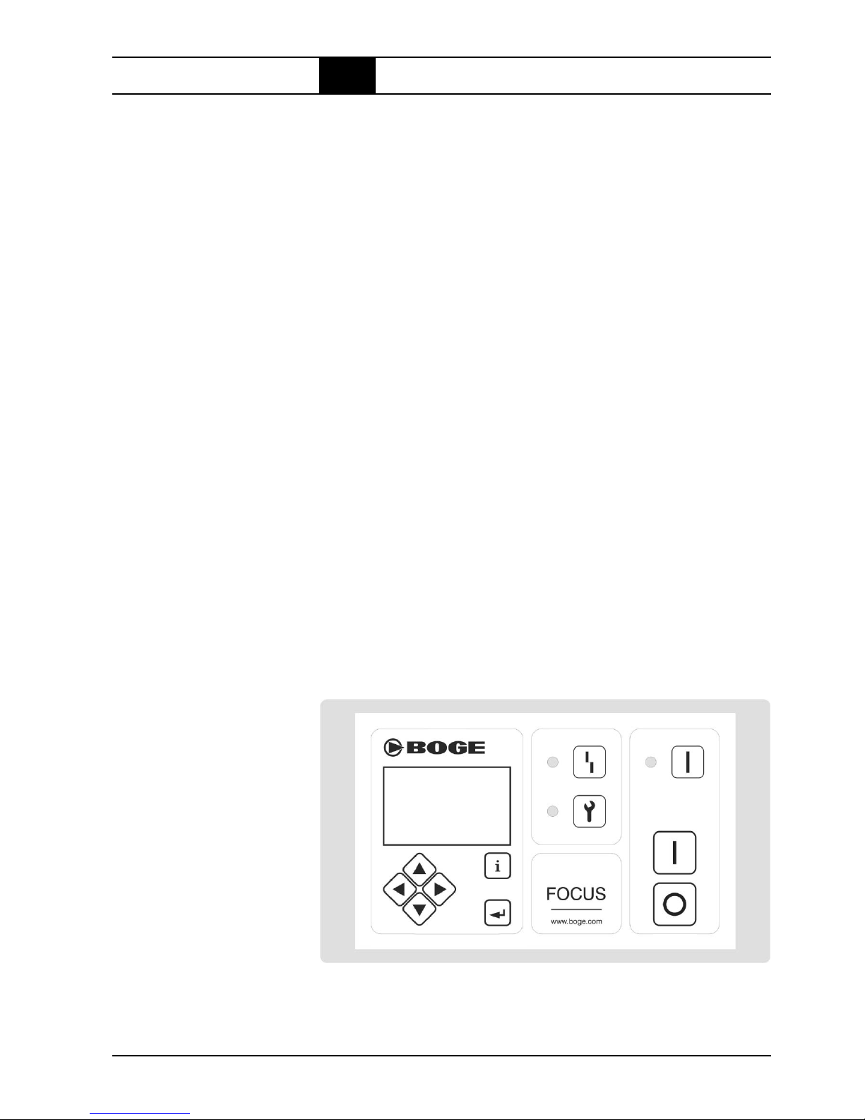
Control unit .....................................................................................1.1
1.2 Operation ...................................................................................... 1.3
Switch on the control ......................................................................1.3
Switch on the compressor .............................................................. 1.3
Ready ............................................................................................. 1.3
Run-up phase................................................................................. 1.4
Load operation ............................................................................... 1.4
Idling ..............................................................................................1.4
Switch off the compressor .............................................................. 1.4
Maintenance................................................................................... 1.4
1.3 Display information ......................................................................1.5
Main display ................................................................................... 1.5
Dryer ..............................................................................................1.6
Servicing ........................................................................................1.6
Operating times .............................................................................. 1.6
Info # 1 ........................................................................................... 1.7
Info # 2 ........................................................................................... 1.7
Date / Time .....................................................................................1.8
Display of version ........................................................................... 1.8
1.4 Setting ........................................................................................... 1.9
Entering of codes in general........................................................... 1.9
Parameter list ................................................................................. 1.9
Set parameters............................................................................. 1.10
Parameters ................................................................................... 1.10
1.5 Grouped parameters / parameter management ....................... 1.15
Servicing interval .......................................................................... 1.15
Parameter factory setting ............................................................. 1.15
Base load switch with additional compressors ............................. 1.15
Timer ............................................................................................ 1.16
1.6 Functions .................................................................................... 1.18
Motor switching limitation ............................................................. 1.18
Power failure cycle protection ....................................................... 1.18
Motor spinning time ...................................................................... 1.18
Star phase time control ................................................................ 1.18
Pressure range selection.............................................................. 1.18
Parameterization of frequency converter ...................................... 1.19
TAN test........................................................................................ 1.19
Part 1:
FOCUS

Page IV BOGE FOCUS compressor control for screw compressors
Inhalt.pm6.5 - USA
Table of contents
1.7 Warning message / Fault message ........................................... 1.20
Warning message ........................................................................ 1.20
Pre-acknowledgement.................................................................. 1.20
Acknowledgement of message 45 (Watchdog timer reset) .......... 1.20
Fault messages ............................................................................ 1.21
1.8 Data of external connections .................................................... 1.22
Basic module................................................................................ 1.22
Analogue output module .............................................................. 1.23
RS 485 module ............................................................................1.23
1.9 Fault messages .......................................................................... 1.24
List of fault messages................................................................... 1.24
1.10 Parameter overview.................................................................... 1.26

FOCUS.pm6.5 - USA
Page 1.1
FOCUS
BOGE FOCUS compressor control for screw compressors
The BOGE control concept1.1
FOCUS is a compressor control unit.
It is installed into the switch cabinet as part of the compressor and serves as
a compressor control device.
Prior to commissioning and before accomplishing any kind of maintenance
or servicing work please read the functional descriptions of both control and
compressor carefully. First and foremost observe the Safety notes in Chap-
ter 1 of the functional description of the compressor.
Power input
Terminals A1 and A2 for 24V AC/DC
Rating: 24V +/–10% 50/60Hz 15W
24V DC +/–10% 0,4A
An interruption of the power supply is effected by means of the mains dis-
connector of the compressor.
Modules
The basic equipment of the FOCUS consists of a basic module and a key-
pad/display unit (TAN).
Amongst others the following modules are optionally available:
– for frequency regulated compressors
– with a 4-20mA output for master controls, suitable for frequency regulated
compressors
– with a (second) RS485 interface for the connection of additional com-
pressors if the first interface is used otherwise
– for compressors with built-in dryers
Interconnection of the modules may only be completed using the provided
leads supplied with the equipment.
The display unit comprises a graphic display and 3 LEDs for an additional
illustration of the operating modes.
Installation
Control unit
Fig. 1.1: FOCUS operating panel
Display
Info-Taste
Enter-Taste
Störung
Warnung
Betrieb
Start
Stopp
Navigationstasten
Display
Info key
Navigation keys Enter key
Fault
Warning
Operation
Start
Stopp

FOCUS.pm6.5 - USA
Page 1.2
FOCUS
BOGE FOCUS compressor control for screw compressors
The BOGE control concept1.1
Navigation keys:
Navigation in the menu, scrolling the displays, scrolling of pages in the pa-
rameter display.
Navigation keys:
Navigation in the menu, displays, dryer status, navigation in the the param-
eter display, setting of values.
Info key
Display of faults, warnings or maintenance messages, log book, quitting of
settings.
Enter key
Confirmation of inputs, selection of parameters, forced idling, setting of FC
(
frequency converter
) parameters.
Off(0) key
Acknowledging when switching on the control, switching off the compressor,
switching off forced idling.
On(1) key
Switching on the compressor, forced idling.
zWarning/Maintenance (LED- orange)
Flashing: Pending warning; compressor is working – as yet.
Lit: Warning already acknowledged; compressor is working – as yet.
zFault ( LED- red)
Flashing: Upcoming fault, compressor is switched off.
Lit: Fault already acknowledged; compressor remains switched off and can-
not be restarted until the fault has been rectified.
zOperation (LED - green)
Flashing: Compressor in idling operation
Lit: Compressor is switched on.
Emergency-Stop pushbutton
The Emergency-Stop pushbutton interrupts the power supply for the contac-
tor coil. The control is still energized and generates a corresponding display.

FOCUS.pm6.5 - USA
Page 1.3
FOCUS
BOGE FOCUS compressor control for screw compressors
Operation1.2
Prerequisite: The compressor must be electrically and pneumatically con-
nected, the power supply voltage must be turned on and the ball valves
and/or balanced disc stop valves between compressor and compressed air
receiver must be opened.
Having connected the compressor to the power supply and having switched
on the main switch, if applicable, the version display is shown (if neither Auto
Restart nor Remote control are parameterized) on which the name of the
control, the name of the manufacturer and the version number are shown.
First a parameter adjustment between basic module and TAN is performed
resp. and if applicable the registration of connected and not yet registered
additional modules. When this procedure has been finished the symbol for
the -key is flashing. Press -key to acknowledge and exit the display.
Otherwise – Auto restart and/or Remote-On-Off is activated:
After the recurrence of the power supply (net power failure) the display shows
a countdown, starting with the set Auto Restart time [s]. When this time is
expired the compressor switches to Ready status and starts automatically,
as soon as the prerequisites are fulfilled.
In case faults occur when the compressor is powered up they are displayed
immediately after the parameter reconciliation. The fault has to be acknowl-
edged to get to the main display (see also Warning message/Fault message).
At first OFF should be displayed in the bottom frame – the status display of
the compressor.
If EMERGENCY-OFF is displayed for the compressor status the Emergency-
Stop button has to be unlocked first.
If the status display shows Fault, the control is faulty and the malfunction has
to be corrected first (see also Warning message / Fault message).
Once this has been accomplished and the display shows the OFF status the
compressor can be put into the Ready status by pressing the -key.
A green LED signals that the compressor is ready for operation and the
pressure control is active – as long as no "Timer-Off" is due or an external
pressure control was parameterized.
If the compressor status Ready is displayed, the compressor is in the
"ready-for-operation" status. That means that the compressor automatically
(re)starts pressure and/or time controlled – as long as the conditions to do
so are fulfilled.
Operation
Switch on the
control
Switch on the
compressor
Ready

FOCUS.pm6.5 - USA
Page 1.4
FOCUS
BOGE FOCUS compressor control for screw compressors
Operation1.2
The compressor motor is started and run up as already described under
'Ready'. The status display changes from Ready to Run-up.
To be able to do so the system pressure at the compressor must be de-
creased and the motor spinning time finished. Furthermore no limitation of
the motor switching cycles is allowed.
Otherwise in the motor status display the display Ready is shown!
For the star/delta contactor combination applies: First the star contactor and
20ms later the mains contactor is switched on. The display Run-up signals
the corresponding status of the control.
The Run-up resp. Star phase is finished after termination of the run-up time
by switching of the control into the Load run status.
When changing into the Load run the control switches on the delivery valve.
Compressors which are controlled accordingly now change into the delta
switching.
Frequency controlled machines display the percentage workload of the fre-
quency converter as a bar diagram.
If the set maximum pressure of the compressor is reached in the load run
the control switches to Idling. Accordingly Idling is shown in the status dis-
play. As a result an automatic system pressure decrease is effectuated.
If no after-running time is set (default: 0sek) the Idling phase is finished as
soon as the system pressure value drops below 1.3 bar (if applicable + para-
meterized max. booster pressure) – provided the automatic limitation of
start numbers allows it – and the compressor changes into the Ready status.
If the compressor is switched off via the maximum pressure and the net pres-
sure drops below the set minimum pressure (Pmin) during the idling time, the
compressor control automatically switches from Idling to Load run – and
the compressor continues with the output.
If the compressor is switched off however during a load run or idling phase
by means of the Off-key resp. Remote-Off it waits with a flashing green
LED in the idling phase (as described above) until the system pressure is
decreased before it changes into the Off status.
With the -key or via Remote-Off the compressor is switched off.
The pressure control is deactivated. If this happens when the motor stands
still or is just operating in the Run-up phase, Off is displayed at once in
the compressor status display and the green LED goes out. Otherwise an
idling phase with flashing green LED is completed beforehand, as already
described in the chapter 'Idling' – last passage.
When operating the control the battery voltage has to be checked from time
to time. If the voltage drops too far a warning message is created. In this case
the battery has to be replaced.
The display of the TAN has to be cleaned with a damped yet not wet cloth
from time to time. As detergents customary household detergents for greasy
surfaces can be used.
No further maintenance is required for the control.
Run-up phase
Switch off the
compressor
Idling
Load operation
Maintenance

FOCUS.pm6.5 - USA
Page 1.5
FOCUS
BOGE FOCUS compressor control for screw compressors
Display information1.3
Main display This is the main display in the control menu. Here the net pressure, the final
compression temperature and the compressor status are displayed (Fig. 1).
By pressing the arrow key 왘왘
왘왘
왘the system pressure (Fig. 2) is displayed instead
of the final compression temperature!
Shows the current net pressure.
Shows the current system pressure.
Shows the current final compression temperature.
Compressor
status
Off
Ready
Run-up
Load operation
% Converter
workload
Idling
Fault
Emergency-Stop
Meaning
Compressor is switched off.
Compressor is Ready and starts automatically as
soon as the conditions are fulfilled.
Compressor is in star phase.
Compressor runs in delta phase, the solenoid valve
is closed.
Display of the workload of frequency controlled com-
pressors. The solenoid valve is closed.
Compressor runs in delta phase, the solenoid valve
is opened.
A fault has occurred on the compressor / compressed
air purification, the compressor is switched off.
The fault has to be rectified prior to a restart.
The Emergency-Stop button has been actuated.
If a dryer module is connected, the actuation of the 왔왖왔왖
왔왖왔왖
왔왖-keys in display 1 or
2 of the main display effectuates that instead of the compressor status the
tendency display of the dryer is displayed.
The tendency display is an indicator for the relative humidity of the com-
pressed air.
With a relative humidity of 25% the display is exactly in the centre.
If the cooling temperature drops to <= 0°C it is entered into the calculation.
The display then moves to the left with decreasing temperatures (into the
direction LO).
If the arrow key 왖왖
왖왖
왖is pressed, the compressor status is displayed again.
Pressing of the arrow keys 왗왗
왗왗
왗왘왘
왘왘
왘leads to the next display.
Net pressure PN
System PS
pressure
Final
compression
temperature
Fig. 1
Fig. 2

FOCUS.pm6.5 - USA
Page 1.6
FOCUS
BOGE FOCUS compressor control for screw compressors
Current ambient temperature
Ratio between load time and total running time in %
Shows the operating hours of the dryer
Shows the operating hours until the next servicing
Room temperature
Dryer efficiency
display
Operating hours
Service interval
counter
Display information1.3
Dryer When connecting the dryer module to the control, an additional page with
the headline "Dryer" is displayed in the menu sequence. On this page the
operating data of the dryer are displayed.
With the next actuation of the
-key you get to the servicing display.
Here the information concerning the servicing times are displayed.
With the next actuation of the -key you get to the operating times display,
on this menu page the operating times of the compressor are displayed.
Servicing
Shows the operating hours until the next motor
servicing.
Shows the operating hours until the next compressor
servicing.
Shows the number of load changes until the next
receiver servicing.
Shows the current voltage of the battery for the real-
time clock in the main module.
Next motor
servicing (h)
Next compressor
servicing (h)
Next receiver
servicing
Current battery
voltage
Operating times
Shows the total operating time of the compressor
motor in hours, minutes and seconds.
Shows the share of time in which the compressor
was idling in hours, minutes and seconds.
Shows the ratio of load energy compared to total
operating time energy since the preceding Reset.
Counts the effected load cycles of the internal combi-
nation receiver. (One cycle consists of 1 x output and
1 x no output each)
Motor running
time
Idling
Efficiency display
Load cycles of
internal receiver

FOCUS.pm6.5 - USA
Page 1.7
FOCUS
BOGE FOCUS compressor control for screw compressors
Display information1.3
Info # 1
Info # 2
Local: keyboard
Remote: Remote-On-Off and/or external output
release
n/a: not installed
Local: via keyboard
Remote: via contact and/or Bus
On: Compressor is switched on
Off: Compressor is switched off
Internal: via internal pressure sensor
External: Output release via contact and/or Bus
Yes: Output release enabled
No: Output lock is active
n/a: No Auto Restart after (control) power failure
Time: Auto Restart active, Auto Restart time
Key switch
On/Off
Output release
Auto Restart
Here the information as to the compressor settings is displayed.
Changes to the displayed settings have to be accomplished by means
of the parameter settings, if applicable, (see also parameter settings) or
by changing the automatically registered configuration.
The information to the control settings as master control resp. the current
status of the integrated timer are displayed here.
Activated pressure range
Current net pressure
– A-Z active timer channel
– n/a no channel active
Set priority sequence, active compressors and time
in h and min until next change of priority.
Pressure range
Net pressure
Timer
Priority sequence
(time until change
of priority)
The priority sequence is only displayed if the number of compressors in the
basic load switching is above 1. In case the number of compressors in the
BLS is set to 1, n/a is displayed here.
The display of the priority sequence shows the currently effective sequence
for selecting the compressors. Depending on the setting the priority sequence
is specified either by the basic load switching or by the timer. For each para-
meterized compressor the current output signal status, the current priority
level and the time until the next priority change, with switched-on BLS, is dis-
played.If only the timer is active (cyclic changing time set to 0) no time is dis-
played.

FOCUS.pm6.5 - USA
Page 1.8
FOCUS
BOGE FOCUS compressor control for screw compressors
Meaning:
C1 C2 C3 means, that the compressors 1–3 are connected and the se-
quence 1, 2, 3 is chosen – in this case none of the compressors receives
an output signal.
C1 C3 C2 means as in the first example, that the compressors 1–3 are
parameterized although they are selected in the sequence 1, 3 und 2 and
furthermore compressor 1 receives an output signal in this case.
The output signal status is shown by means of a black background in the
graphical presentation of the compressors in the display.
Changes to the displayed data have to be accomplished by means of
the Basic Load Switching or Timer settings (see also: parameterizable
settings).
This menu page shows the current setting of the real-time-clock.
The time is displayed in hours, minutes and seconds and the date with day
of the week, day, month and year.
In case of a switched-off power supply the real-time-clock is operated by its
battery – provided the plug-in jumper contacts arranged next to it are con-
nected and their voltage is sufficient (see also chapter servicing).
To be able to set time and date only the -key has to be pressed. The cursor
jumps to the time display and the place value for hours starts blinking.
This value can only be adjusted by means of the
-keys.
With the -key the input is acknowledged and the cursor moves to the next
field.
Proceed the same way with all other place values until all values are cor-
rectly adjusted. In case a value has to remain unchanged just actuate the
-key, to jump to the next value.
To leave the time adjustment, actuate -key until none of the place values
is blinking any longer. Actuate
-key to reach the previous page or actuate
the
arrow key to go to the next page.
If the -key is actuated while adjustments are made to the real-time-clock,
this setting is left without accepting the parameterized changes.
The version display can be reached in the menu by pressing the
or
keys.
Here the name of the control, the software number and the manufacturer
are displayed.
If the
key is pressed now you get to the Module Info display.
Here the addresses and the installed software versions of the connected
modules are shown.The first display refers to the basic module (Address: 0),
all other connected modules can be displayed by actuating the
keys.
Basic module: – 0, TAN: – 1, FC module: – 10, Dryer module: – 20,
RS485 module: – 30, analogue output module: – 4X.
If the display of a module is flashing the communication with this module is
faulty.
You can leave Module Info by actuating the -key.
Display information1.3
Date / Time
Display of version

FOCUS.pm6.5 - USA
Page 1.9
FOCUS
BOGE FOCUS compressor control for screw compressors
1.4
Entering of codes
in general
1. Actuating the arrow key
leads from the main display 1 to the version
display.
2. If now the -key is actuated, a display is shown asking you to enter a
5-digit code (see code list.)
3. The first place value of the code is blinking. By means of the arrow keys
and
a digit can now be changed.
4. By actuating the -key or the
-key the cursor jumps to the next value
and the value can be changed accordingly.
5. Once the last digit has been set the code is acknowledged by actuating
the -key.
According to the entered code either windows for various settings or a
parameter list opens. When entering the second ... fifth digit actuating the
-key causes an erasing of the previous digit, so that it can be entered
again.
Actuating the -key when entering the first digit the code setting is left
and you return to the version display.
Meaning
User- Code / parameter list
Parameter display / access previous code
Setting/Resetting servicing intervals
Parameter restoring
Timer settings
BLS settings
CODE
17391
00000
00111
00988
00798
00832
If the user code, service code or BOGE code is entered it is possible to
return to the previously left parameter list within 15 minutes after hav-
ing left this list, without having to enter the code once more.
If one of the codes for the parameter list is entered (User code, Service code,
BOGE code) it depends on the entered code which of the parameters can
be processed.
An arrow at the beginning of the line shows where the cursor is currently
positioned and if a value under this code can be changed.
If only the outline of the Öarrow is displayed, the value under this code
cannot be changed, if the arrow is completely filled Î, the value can be
changed.
In the parameter setting actuating the
and
-keys makes the cursor move
one parameter forwards or backwards. Use
and
-keys to scroll to the
previous/next page.
To leave the parameter list actuate -key and you get back to the main dis-
play.
If you are in the adjustment range of a parameter, it can be left again by ac-
tuating the -key.You have to actuate the -key once more to close the list.
Parameter list
Setting

FOCUS.pm6.5 - USA
Page 1.10
FOCUS
BOGE FOCUS compressor control for screw compressors
Set parameters
Setting1.4
1. Opening of the parameter list by means of the desired code (User code,
Service code, BOGE Code)
2. If the cursor points at the parameter which is to be changed, e.g.maximum
pressure in the pressure range 1 (P012), this selection is acknowledged
by actuating the -key.
3. If a digit (e.g. 9 bar) is blinking on the right side of the parameter, the de-
sired value can be set (e.g. 10 bar) by actuating the
-keys.
4. By actuating the -key this input is acknowledged and stored!
Actuating the -key at this place causes a leaving of the setting without
accepting the changes.
You can proceed with every parameter in the same way.
The setting of the parameters can be accomplished as described above.
P001 Language
Here the language for the control can be selected; at the moment German (D)
and English (GB) are supported.
P012 Pmax Pressure range 1
Pressure range 1 is the default pressure setting for the compressor.
Here the upper pressure target value for pressure range 1 is set. As soon as
the net pressure has reached Pmax the compressor changes from load run to
idling.
P013 Pmin Pressure range 1
Pressure range 1 is the default pressure setting for the compressor.
Here the bottom pressure target value for pressure range 1 is set.If the com-
pressor is in the Ready state and the net pressure drops below Pmin, the
compressor starts with the output.
If the pressure range selection is effectuated by a master control or the
external contact you have to observe when setting the pressure ranges,
that in case of a power failure or fault of the master control, the com-
pressor control eventually falls back on this pressure range.
P014 Pmax Pressure range 2
Pressure range 2 offers the possibility for pressure decreases – the value
must not be set above that of pressure range 1.
Here the upper pressure target value for pressure range 2 is set. As soon as
the net pressure has reached Pmax the compressor changes from load run to
idling.
Pressure range 2 is only active if corresponding adjustments of the timer have
been made and/or the external contact for the pressure range selection is
active.
P015 Pmin Pressure range 2
Pressure range 2 offers the possibility for pressure decreases – the value
must not be set above that of pressure range 1.
Here the lower pressure target value for pressure range 2 is set. As soon as
the net pressure drops below Pmin, the compressor starts with the output.
Pressure range 2 is only active if corresponding adjustments of the timer have
been made and/or the external contact for the pressure range selection is
active.
Parameters

FOCUS.pm6.5 - USA
Page 1.11
FOCUS
BOGE FOCUS compressor control for screw compressors
P020 Auto Restart
Switching On/Off of the Auto Restart function (network independent on-off
memory).
Normally the version display is shown after a power failure, which must be
acknowledged by actuating the -key, before the control displays the Off-sta-
tus and the alarm relay returns to the status "no fault".
If the Auto Restart function is active and the compressor was previously
switched-on an adjustable count down is started after power recovery (Auto
Restart time P021).
When this time is elapsed the compressor automatically returns to the Ready
status.The pressure control is active and on demand the compressor resumes
the output.
If P020 is set to the value 1and Auto Restart is activated. If the value 0is
set the Auto Restart is deactivated.
When switching-off the compressors with the Emergency-Stop button the
Auto Restart function is not active.
P021 Auto restart time
The time set in seconds is the time that elapses after a power failure, before
the compressor starts again with activated Auto Restart or Remote On/Off.
P022 Short stop time limiting value
The time set in seconds is the time that should elapse at least after a motor
stop before the switch-on pressure value of the air supply network is reached
or dropped below again.
To be able to do so the FOCUS control constantly monitors the air supply
network and "learns" the necessary data. Thus these data are automatically
kept in case of net structure changes.
The default value should only be changed if agreed upon with BOGE Service
beforehand.
P031 After-running time
Interval during which the compressor remains at least in the idling phase
after a load run, before it switches to Ready or Off status.
This value is normally set to zero. Under special circumstances increased
after-running times may be necessary, which can be set at this place.
P032 Anti freeze protection
Here the automatic anti freeze protection can be rendered inoperative.
If the compressor is in Ready status and the oil temperature (final compres-
sion temperature) drops below 5°C, the compressor starts automatically and
runs in idling until the oil temperature reaches 20°C again.
If P032 is set to the value 1the automatic anti freeze protection is deacti-
vated, if the value 0is set the anti freeze operation is active. The value 0 is
given as default value.
P034 Continuous operation
If pressure losses have to be avoided at any cost in case of relatively small
receivers or compressed air net volumes, a continuous operation can be ac-
tivated here.
In case of an activated continuous operation the control never switches back
to the Ready status. The compressor constantly runs in Idling if it is not de-
livering compressed air.
The value 1means that the continuous operation is active, 0means that the
continuous operation is deactivated.
Setting1.4

FOCUS.pm6.5 - USA
Page 1.12
FOCUS
BOGE FOCUS compressor control for screw compressors
Setting1.4
P044 Message type for oil filter
By this parameter it can be declared whether a pending message of the oil
filter monitoring is defined as a warning or as a fault. This adjustment has
effects on the properties of the control. Whereas for a warning only a mes-
sage is created, the compressor is additionally cut off at once as soon as the
parameter is defined as a fault.
In this case the setting 1 menas Fault and the setting 0 Warning!
P050 Modbus address
The set value 0-248 indicates the Bus address of the RS485 interface on
the basic module for the communication with an external Bus system – e.g.
a master control.
For the settings of the integrated BLS the value 0 is available for the master.
Additionally connected compressors have to be specified with the values 2 – 4.
For other applications the address can be matched with the requirements.
All addresses from 1-248 are possible
P051 Modbus baud rate
The value shown here indicates the data signalling rate [Bits/s] of the RS485-
interface of the main board for the communication with an external Bus sys-
tem – e.g. a master control.
P052 Modbus frame
The protocol frame is determined here. 8 data bits are transmitted and the
parity can be selected (O = Odd, E =Even or N= None), as well as the number
of stop bits. (1 or 2)
P053 Modbus address (module)
The set value 0-248 indicates the Bus address of the RS485 interface on the
basic module for the communication with an external Bus system – e.g. a
master control.
0 stands for master, additionally connected compressors have to be specified
with the values 2 – 4.
P054 Modbus baud rate (module)
The value shown here indicates the data signalling rate [Bits/s] of the RS485-
interface of the module for the communication with additional compressors.
P055 Modbus frame (module)
The protocol frame is determined here. 8 data bits are transmitted and the
parity can be selected (O = Odd, E =Even or N= None), as well as the number
of stop bits. (1 or 2)
P060 Contact type for compressed air purification
By this parameter it can be declared whether the signalling contact for the
compressed air purification is a break contact or a make contact.
0 Break contact
1 Make contact
P061 Message type for compressed air processing
With this parameter it is determined whether the pending message of the
compressed air processing is defined as a warning or as a fault. This setting
has an influence on the performance of the control. Whereas in case of a
warning only a message is released, the compressor is additionally switched
off at once when this parameter is defined as a fault.
In this case setting 1 means fault and setting 0 warning!

FOCUS.pm6.5 - USA
Page 1.13
FOCUS
BOGE FOCUS compressor control for screw compressors
Setting1.4
Meaning
Internal release
Release via contact
Release via contact and an external BUS
Setting
0
1
2
If a RS485 module is used and parameterized to an address above 0 – its
rotary switch must point to zero in any case – it serves automatically as an
external output release.
P064 Monitoring of an external release appliance
The parameter P064 is relevant if the pressure control is effectuated externally
via the digital input and compressed air has to be available continuously – i.e.
no switch-off during the night or on weekends seems to be sensible.
If the parameter P064 is set to the value 0the monitoring of external output
release is deactivated, if the value 1is set, the monitoring is active.
In case of activated monitoring the FOCUS automatically switches to internal
pressure control and outputs an appropriate warning message as soon as a
fault of the external control is registered.
P065 Remote Start-Stop
This parameter determines the ON/Off switching function of the control via
Tan, a potential-free contact or the Bus. In case the parameter is selected
unequal 0, a switching On or Off via Tan of the FOCUS is no longer possible.
Meaning
The On/Off switching is effectuated solely by the control
keyboard (local)
The On/Off switching is effectuated solely by the input
Remote-Start-Stop-switch (continuous contact)
The On/Off switching is effectuated solely by the BUS inter-
face
The On/Off switching is effectuated solely by the continuous
contact – release function – and via the BUS interface,
however not via the control keyboard.
Setting
0
1
2
3
In case of Remote-On-Off the Auto Restart time (P021) after a power failure
is used for an automatic start delay.
P063 External release
The kind of external release is set by this parameter.

FOCUS.pm6.5 - USA
Page 1.14
FOCUS
BOGE FOCUS compressor control for screw compressors
Setting1.4
P066 Key switch
The function of the key switch is set here:
Meaning
The key switch has no function, it is deactivated.
When actuating the key switch, the function Remote-Start-
Stop is activated.
When actuating the key switch the external output release
is activated.
When actuating the key switch both the external output
release as well as the Remote-Start-Stop function are
enabled.
Setting
0
1
2
3
The settings for external output release (P064) and Remote-Start-Stop
(P065) have to be effectuated separately under the corresponding param-
eter numbers.

FOCUS.pm6.5 - USA
Page 1.15
FOCUS
BOGE FOCUS compressor control for screw compressors
Grouped parameters / parameter management
1.5
Servicing interval If the code 00111 is entered, a display for the servicing intervals is opened.
The servicing intervals fort he compressor, the motor and the receiver are
set here. If a dryer module is connected the servicing interval fort he dryer
can be set here as well.
The servicing interval for compressor, motor and dryer are specified in hours,
consists of 1 x output and 1 x no output each).
With the 왔왖왔왖
왔왖왔왖
왔왖-keys the corresponding servicing interval is selected and ac-
knowledged by means of the -key. Now the digit starts blinking and can be
changed using the 왔왖왔왖
왔왖왔왖
왔왖-keys. Only after having acknowledged and entered
the value by means of the -key the new servicing interval is accepted and
the corresponding down counter restarted.
By means of the -key this setting can be left without saving the changes or
the counter reading.
The display of the servicing intervals can also be left by means of the -key.
With the setting of 2.000.000 receiver load cycles this down counter is de-
activated.
In case somebody has changed any parameters and wants to recover a
functionally safe status the factory setting resp. commissioning setting can
be restored.
To do this the compressor must be in the OFF status.
Only then the code 00988 can be entered.
In the displayed window you can read: Restore and you can select eitherYes
or No.
Should the saved parameters be restored, you can use the 왔왖왔왖
왔왖왔왖
왔왖-keys to select
Yes and acknowledge by means of the -key.
Now the current data on the basic module are overwritten with the factory-set
values.
If the code 00832 is entered you get to the settings for the integrated basic
load switching.
The BLS controls at least 2, and a maximum of 4 compressors.
In adjustable time intervals (1-250 h) the priority sequence of the compres-
sors changes. The BLS is designed for compressors of the same size.
Display:
On the top left the number of compressors is displayed, below the interval
time, and on the right hand side Pmin (P1.1) and Pmax (P1.2) of pressure range 1.
By actuating the 왔왔
왔왔
왔-key Pmin (P2.1) and Pmax (P2.2) of pressure range 2 (pres-
sure decrease values) are displayed.
Base load switch with
additional compressors
Parameter
factory setting
for the receiver the load cycles of the internal receiver are counted (One cycle
Other manuals for FOCUS
1
Table of contents
Other Boge Control Unit manuals