Bolecki SKN User manual
User’s manual for distillation column controller
“SKN” from version 2.07
Please read this manual carefully before first o eration of the
controller.
Firma Bolecki Tel. 503-064-713 (8 – 21)
32-650 Kęty forum.bolecki.pl
INFORMATION FOR THE CONSUMER
The symbol resented on roducts or in documentation enclosed with
them informs the non-o erational electrical or electronic a liances
shall not be dis osed together with munici al wastes. When dis osal,
recycling of recovery of subassemblies is necessary, the right
roceeding is to give over the a liance to a s ecialized collection oint,
where it will be taken over free of charge.
1. INSTALLATION RECOMENDATIONS.........................................................................1
1.1. HIGH-VOLTAGE PART...........................................................................................2
1.2. LOW-VOLTAGE PART............................................................................................3
2. FIRST TURN ON AND CONFIGURATION...................................................................4
3. SERVICE MENU...............................................................................................................4
3.1. SEMI-AUTOMATIC MODE.....................................................................................4
3.2. INPUT/OUTPUT TEST.............................................................................................5
3.3. RESET........................................................................................................................5
3.4. ADDITIONAL SETTINGS........................................................................................5
3.4.1 DISPLAY SETTINGS.........................................................................................6
3.4.2 OUTPUT SETTINGS..........................................................................................6
3.4.3 SENSORS SETTINGS........................................................................................8
4. PROCESS SETTINGS MENU.........................................................................................8
4.1. HEATING...................................................................................................................
4.2. ENFORCED WATERING.........................................................................................
4.3. COLUMN STABILIZATION....................................................................................
4.4. HEADS COLLECTION.............................................................................................
4.5. HEART COLLECTION.............................................................................................
4.6. TAILS COLLECTION...............................................................................................
4.7. PROCESS ENDING.................................................................................................10
5. THE APPLIANCE OPERATION...................................................................................10
6. MEMORY CARD...........................................................................................................10
6.1. OPERATION PARAMETERS REGISTER............................................................10
6.2. SOFTWARE UPDATE............................................................................................11

The SKN controller is designed to control the rocess in LM/VM distillation columns.
Functions of the controller make the column o eration much easier. Main features of the
controller:
- Two inde endent out uts 16A 230/400V.
- Cooling water electrovalve (NO relay out ut)
- LM electrovalve (max 12V 1,5A NO/NC)
- VM motorized valve (max 12V 40mA)
- Four thermometers with resolution of 0.01oC, including one of two sensors, which
could control the VM valve
- Gra hic dis lay with high contrast
1. INSTALLATION RECOMENDATIONS
It is recommended to install the actuator in the area of heaters, in an enclosure rotecting it
against accidental flooding (having in mind such cases like leaking water connections, etc.).
At the same time, the enclosure must rovide free air flow that is necessary for cooling the
SSR relay controlling the heaters. The late should be fixed to the enclosure with lastic
s acers rovided in the kit. Using metal s acers may lead to a short-circuit, damage of the
a liance or even electric shock of the user.
The control anel should be installed in a
convenient lace, having in mind there is
a slot for memory card at the to of the
anel – flooding the a liance from this
side for sure would cause the electronic to
be flooded. The anel is rovided with its
dedicated bracket. Put the anel on the
bracket and then ull it down.
- Remember, the a liance is su lied
with a dangerous voltage. Its electrical
connection should be entrusted to a
erson with suitable knowledge and
authorization. It is forbidden to use the
a liance when its enclosure or wiring
is damaged, also if there is only
sus icion of malfunction of the system.
- The a liance may activate its out ut
at any time without signaling this
event, even if does not result from its
o eration cycle. It is forbidden to make
any mani ulation on the electrical art
of the system when it is connected to
the mains. It a lies also to the low-
voltage elements.
- Do not turn the a liance ON when
the heaters are not covered with liquid
– in case of unex ected turning ON
they could be damaged. It should be
considered to install additional
(mechanical) heaters switch.
- The SKN controller has incor orated
electronic relay (SSR) controlling the
heaters, however it does not ensure
reliable, mechanical heaters
disconnection. Moreover, in case of its
failure (overloading, short-circuit, etc.),
most likely it will su ly the heaters
with full voltage.
- The su ly connection should be
easily accessible. It must ensure quick
and trouble-free disconnection of the
system form the mains at any time.
- The wires and connectors used should
be suitable for the a liance ower. It
is recommended to install a ro riate
terminal box with a ro riate breakers
and differential rotection.
1
- Perform eriodical maintenance of the
a liance. After first few cycles of
o eration, check es ecially the
connections o erating under
significant load, retightening might be
necessary.
- It is forbidden to use the system in
laces that can catch fire from the
wires used, it is forbidden to store
flammable materials in the
neighborhood of the system o eration.
-
- Metal elements of the a liance
must be grounded. Please kee in
mind the fluids are erfect
conductors, therefore each
element must be grounded even
though a arently it is isolated
(e.g. with hose) from the other
elements.
- It is forbidden to leave the system
connected to the mains without
su ervision of a erson with suitable
knowledge and skills.
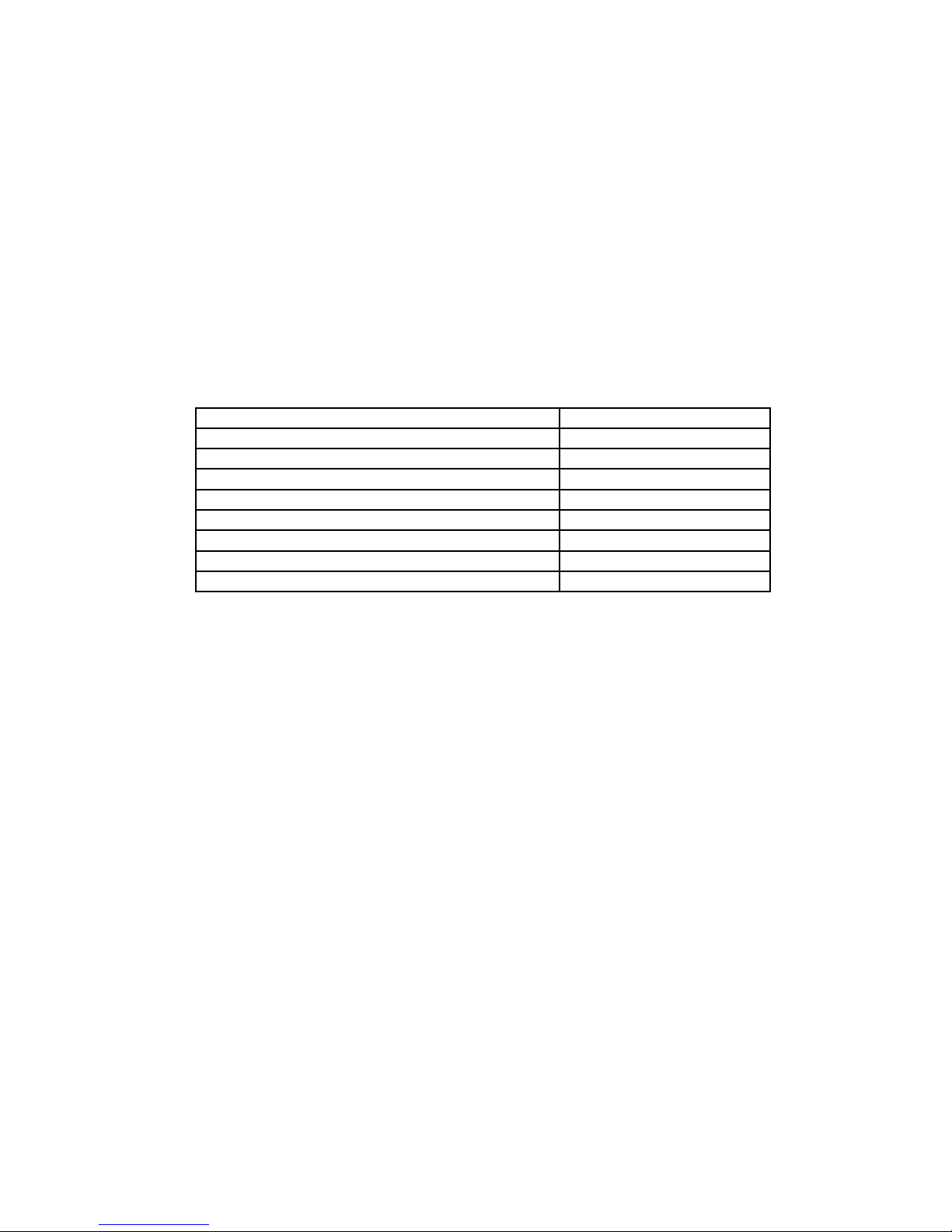
Electronic su ly voltage 230V AC +/-30%
Electronic ower consum tion Max 18W
Heaters su ly voltage Max 400V AC
G1 & G2 out ut current Max 16A each
Water valve max current 1A
LM valve max current 1.5A
VM valve max current 40MA
Tem . measurement resolution 0.01oC
Tem . measurement accuracy +/-3oC (0 – 100oC range)
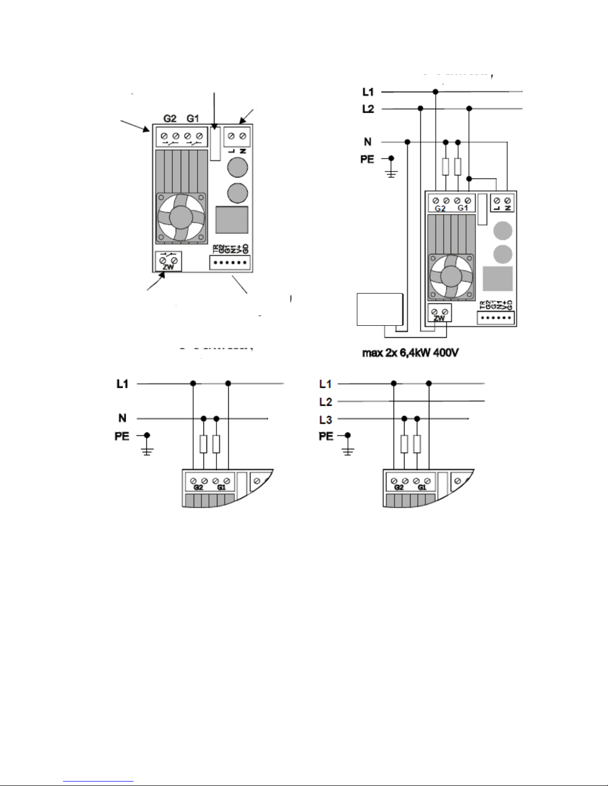
1.1. HIGH-VOLTAGE PART
The following diagrams show the exam les of connection of this art of the a liance. The
mains voltage that is necessary for the electronics shall be connected to L N terminals,
aying attention the hase wire should be connected to “L”.
2
Water valve. The SKN controller is not designed to su ly the water valve from its own
ower su ly. The water valve should be su lied from the mains 230V or se arate ower
su ly. The ZW connector should be sim ly considered as a switch, which will close its
contacts when the controller wants to activate the water circulation. It enables to use only
NC valves.
The heaters, de ending on their o eration voltage, should be connected according to one of
the diagrams, considering GH1 and G2 out uts as the serial switches. If the heaters (or their
sections) are of different ower, remember the ower connected to the articular out ut – it
will be needed for further configuration of the a liance.
ATTENTION! The “ rey” factory enclosure of the execution part ensures proper
coolin for current sup to 10A (for each G1 and G2). If the excepted current is to be
hi her, it should be considered to place the execution part in different enclosure
providin adequately better ventilation.
3
FUSE
HEATRES
RELAY
230V
SUPPLY
WATER VALVE
RELAY
CONTROL PANEL
CONNECTOR
WATER
VALVE
max 2 x 3.6kW 230V
max 2 x 3.6kW 230V
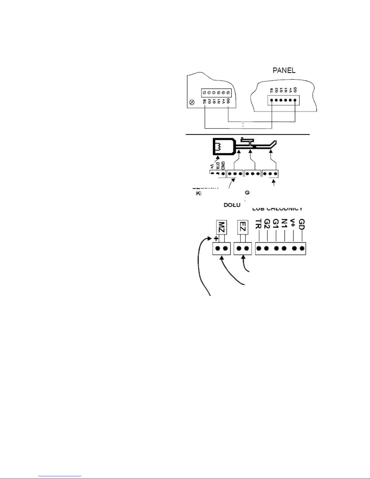
1.2. LOW-VOLTAGE PART
The control anel and the execution art
should be connected with the cable
enclosed. The res ective terminals should
be connected at both ends (i.e. GD-GD, V+-
V+, etc.). There is a connector at the anel
that could be easily detached.
The temperature sensor should be
installed in the column according to its
manufacturer recommendations, leaving
circa 1 cm of the metal art rotruding, if it
would be necessary to remove it ( ossibility
to hold it with liers, etc.). The measurement
oint of the column should be connected
with res ective terminal of the anel.
DS18B20 circuits, o erating in “normal” or
arasite ower, are used as the tem erature
sensors, the wire colors are im ortant.
Ground (GND) is brown, Data line (viewed
from the connectors and label side) (DTA) is
white, su ly is green. Mistake could
damage the sensor.
The LM electrovalve should be connected to
the EZ connector. Polarization (+/-) is not
im ortant. The electrovalve cable, due to
interferences created in it, should be shielded
and ossibly short, should not be ut in harness
with other cables. The controller enables control
of both NO and NC valves, a ro riate
configuration to be done in menu.
VM valve has an incor orated drive, thanks to
which, the controller may control its o ening
rate inde endently. It should be connected to
the MZ connector. Connecting here not
recommended element may lead to the out ut
failure. Polarization is im ortant, one of the wires is always red and it should be connected
to “+”. In case of inverted connection, the valve would o erate in o osite direction making
the column correct o eration im ossible. Correct installation could be check by means of
in ut/out ut test ( oint 3.2), where the symbol “+” visible on the dis lay means o ening and
“-” – closing.
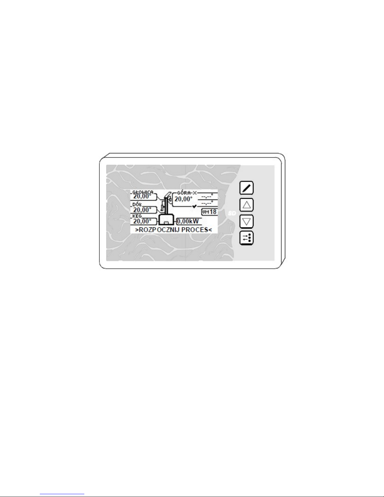
2. FIRST TURN ON AND CONFIGURATION
After making sure that everything is installed correctly, fill u the tank or disconnect the
heaters and turn on the su ly. After a few seconds, the a liance should dis lay the main
screen with the column diagram and tem erature values in its articular elements. It is
recommended to erform a few o erations in the service menu.
1. Restore factory settings (o eration described in oint 3.3).
4
EXECUTION
BOARD
KEG’S
SENSOR
BOTTOM
SENSOR
COLUMN
OR COOLER
SENSOR
TOP
SENSOR
LM ELECTRTOVALVE
VM MOTORIZED VALVE
Here to connect the red motorized
valve wire

2. Check o eration of articular out uts, select o eration oints of VM and LM Valves
(3.2).
3. Configure initially the controller ( oint 3.4)
3. SERVICE MENU
This menu includes essential arameters of the controller. To enter this menu, ress and
hold for e few seconds the button, when the logo screen a ears ress the button
and wait for e few seconds. Navigation within this menu is done with the buttons,
select a ro riate function with . To exit this menu ress and hold for e few seconds the
button or turn ON the su ly again.
3.1. SEMI-AUTOMATIC MODE
This function makes it ossible to control the rocess with significant artici ation of the
user without alarms signalization. The user may, at any time, change the ower and turn the
cooling water valve ON/OFF. The only automatic function is VM valve control on the basis of
tem eratures entered by the user. The to value is an OFF tem erature, and the bottom
value is an ON tem erature. To sensor or bottom sensor is used to control this valve,
according to settings in menu 4.5. Setting of the VM valve o ening rate is done same way
as in the automatic mode.
T1…T4 designations refer to successive tem erature sensors (T1 is the head, T2 – bottom,
etc.). When entering this function, the clock visible in the u er art of the screen is
activated. It does not control the rocess, it is only to hel the user.
In this mode, data logging into SD card is also active. Holding for a few seconds the
button de ressed would cause the controller restarting. To acce t the new valve osition,
ress the button (editing this arameter) or sim ly move to edit next arameter ( ress
the button).
3.2. INPUT/OUTPUT TEST
In this menu, each out ut can be activated manually. The button activates the out ut,
the button deactivates the out ut. Transition between arameters is loo ed and it is
done with the button. To exit this menu ress and hold for e few seconds the
button or turn ON the su ly again.
Control of the VM valve, designated as MZ is done with the buttons. The visible “+’
symbol should cause the valve o ening and “-“ its closing, 0 means the valve is sto ed.
Control of the LM valve, designated as EZ is done with changing the values – above some
threshold the valve “engages” and below “releases”. To find the o timal value controlling the
valve, carefully increase the value and note when the valve o erates. Increase this value
further by circa 10...15%, then disconnect and reconnect the valve connector aying
attention if this o eration has roduced next and unequivocal vale o eration within 30 s.
Then enter the value obtained as Dt arameter value in out ut settings ( oint 3.4.2).
Setting too high values could cause the ower su ly overload and its shut-down (controller
restart). If such effect occurs without the valve o eration, it means this valve is not suitable
5
for this controller. Quite squealing or delayed o eration of the valve after disconnection of its
connector is a natural behavior.
3.3. RESET
Hold the button de ressed for a few seconds – the controller will restart. At the moment
when the logo screen a ears, ress the button, shortly after instead of main screen
the menu with a list of o erations will a ear. With the button move to “reset” and ress
the button. The controller will restart with factory settings. This function does not “cure”
the controller wonderfully and it is not a solution for all the roblems with its o eration that
usually might arise from not understanding its rinci al of work and wrong settings. Instead,
it causes necessity of resetting all the arameters.
3.4. ADDITIONAL SETTINGS
Hold the button de ressed for a few seconds – the controller will restart. At the moment
when the logo screen a ears, ress the button, shortly after instead of main screen
the menu with a list of o erations will a ear. With the button move to “additional
settings” and ress the button, first arameters – dis lay contrast – will come u .
Change the value with the buttons, confirm the value and move to next arameter
with the button. It is not ossible to move back to revious arameter. To save the
changes move across all the arameters. The controller will restart.
3.4.1 DISPLAY SETTINGS
Here you can select the LCD screen contrast.
3.4.2 OUTPUT SETTINGS
Here you can select the LCD screen contrast.
LM TYPE – s ecify the valve ty e (NO – normally o en or NC – normally closed)
Dt – arameter controlling the valve. The SKN controller controls the electrovalve in
so histicated way, in order to reduce heating of the valve and make it ossible to use valves
form a wide range of valves, which would not be suitable for direct o eration with this
a liance (e.g. excessive coil ower, o eration voltage different then 12V). Correct value of
this arameter should be obtained testing the valve o eration, available in the menu
“In ut/Out ut test” ( oint 3.2).
Then you could define how the heaters will work.
G1 modulated, G2 continuous – Heater connected to G2 out ut will o erate continuously,
even if set at minimum ower. Essential ower adjustment will be done with G1 heater.
G1 and G2 modulated. Both heaters will be turned On and Off at the same time.
G1/G1 power – the controller shows absolute ower in kilowatts (kW), not relative in
ercents. Therefore, to obtain correct value it is necessary to enter nominal ower of
articular heaters. Both the above ways of control have one common feature, the controller
realizes so called grou control with a few seconds eriod. Contrary to hase control, it
eliminates the necessity to use ex ensive noise filters, ensures good quality of control,
however it may cause light dimming in ace of heaters o eration. Therefore, it is
6

recommended to work in mode of G1 modulated and G2 continuous, where the modulated
heater will be su lied form different hase then lighting.
Max VM openin – defines the maximum valve o ening. When running the rocess it will
be im ossible to select higher valve o ening, reducing the ossibility to select higher
ca acity then the column can rovide and frequent rocess destabilization at beginning
hase of collecting the heart.
Min VM openin – means minimum o ening. When running the rocess it will be
im ossible to select lower o ening. Also the controller itself will no go below this vale if the
o ening correction o tion is active. Use a value at which the rate of collection is still
reasonable. Setting too low value or even total closing would cause the controller to
encounter a roblem with transferring to tails when the close time rinci le is selected, or
would case unnecessarily long collection of the heart and energy consum tion.
7

8

3.4.3 SENSORS SETTINGS
This menu consists of two screens. In the first of them you can define what sensors will be
connected the controller, and therefore their correct o eration should be checked.
Sensor alarm – leaving the sensor crossed out informs the controller that give sensor will
not be connected. The selected sensors are being checked only during rocess running
(before you can disconnect them freely). If during rocess running the controller detects a
roblem, a ro riate message will be dis layed and acoustic signal will sound.
From this moment, the user has a minute to confirm/cancel the error by ressing any button,
otherwise after indicated time the controller will sto the rocess.
The error will be cancelled automatically if the sensor comes back to its normal o eration.
Next error from the same sensor would a ear only if even for a moment correct signal from
this sensor rea ear, it means ermanently defected sensor would be signaled only once.
Such method of roceeding ensures determined reaction to an error, however excludes
immediate and not necessary column shut down e.g. due to accidental sensor
disconnection. It gives the user ossibility to make ro er decision without needless stress.
Head sensor as – to select head or cooler.
This function brings also changes in the main screen or rocess menu. Setting the sensor
as a head sensor would add to menu an additional o tion of rocess ending after obtaining
at it the s ecified tem erature (without it, still the other sensors will be selectable).
Setting the sensor as a cooler sensor would add an additional o tion of the cooler
tem erature control.
Readin correction. This o tion enables correction of the tem erature sensors readings.
Value in arenthesis shows an actual tem erature taking into account the correction
entered. Please remember the DS18b20 sensors are quite good thermometers and
ractically offers much smaller error then described in the s ecifications. Small difference
from the actual tem erature is meaningless for the controller, so this correction is urely a
cosmetic function. Differences exceeding a few degrees might indicate sensor defect.
4. PROCESS SETTINGS MENU
Here you can configure the entire rocess. To enter this menu, ress the button at the
moment when main screen is visible and no arameters are being changed. To exit this
menu, res the same button again. The buttons rewind the menu or change
arameters values after entering the editing menu.
Entering the editing of a given screen, moving to next arameters, and exiting the editing is
ossible with the button.

Turning Off and long holding of the button de ressed when making changes would not
save them (saving into memory is done with exiting the editing).
Princi les of the rocess might be also changed during its running. Remember, however,
such changes have immediate im act so unex ected rocess interru tion or move to next
hase may ha en. The entire distillation rocess runs according to subsequent, below
listed rinci les.
4.1. HEATING
First rocess stage. Here you can define the ower of heating, at what tem erature of the
column bottom the electrovalve of cooling water should be activated and what tem erature
of the column to should start the watering stage.
4.2. ENFORCED WATERING
Consists of three attem ts of watering with auses the ur ose of which is better wetting of
the column acking. This o tion is aimed at controlled filling of the column with water. When
not sure how to set u these arameters, it is recommended to set u much longer time
then exce ted (even tens of minutes) and control the watering rocess with self-contained
changes of ower form the main screen. And then enforce transition to a next stage
(described in oint 5). Such method ensures comfortable work without a ressure of time
and necessity of restarting the rocess in case of its omitting.
4.3. COLUMN STABILIZATION
This rinci le determines the ower and time of stabilization.
4.4. HEADS COLLECTION
Fourth stage. This rinci le defines the ower effective from this moment and a time for
which the user can collect so called kindling and heads. During this stage the LM valve is
being o en, and the VM valve is still closed.
4.5. HEART COLLECTION
Fifth stage. This rinci le defines how the main roduct will be collected, the user decides
what jum from the tem erature of the day is to cause the end of collection. Which sensor
(column to or bottom) will control the VM valve. Beginning value of the VM valve o ening
and a ste decreasing each next valve o ening. The tem erature of the day is to be defined
automatically by the controller during its o eration. From the moment of starting this stage,
the user may at any time, from the main screen, change the o ening/closing tem erature
and the current valve o ening level. For the time of heart collection, the LM valve is being
closed.
4.6. TAILS COLLECTION
Sixth stage. The VM valve is being closed, the LM valve is being reo ened. This stage can
be induced if the selected rinci le is met. You can select the ty e of sensor (keg, bottom or
to ) and tem erature value to be obtained at this sensor, or maximum time of the VM being
closed. In order to use the tem eratures in articular column oints, first it is recommended
to erform the column test and find out these values (s read of the sensor arameters, the
column o eration conditions, etc.).
10
A better solution might be the rinci le of VM closing time. When the column is good (and
the accessories set correctly), the valve will start to close in the very ending hase of
collection and each next closing will be longer and longer. The so far observations indicate
the time of a level of 10 min. should be enough.
4.7. PROCESS ENDING
With ro er arameters setting, in this rinci le the controller may end the rocess directly
from the heart collection (ski ing the tails). The user defines how long the cooling shall be
active after the heaters are turned off, and how to detect the end of rocess. It could be in
result of exceeding the tem erature in the KEG or the column bottom or to .
5. THE APPLIANCE OPERATION
The main screen with the column view enables a few functions such as beginning and end
of rocess, transition to next stage or modification of arameters during o eration. Enter the
functions selection by ressing the button. When the rocess is sto ed, it is ossible
only to restart the rocess ( ressing the button). During rocess running you can move
to a next stage, quickly change the VM valve tem erature, change the ower currently used
or end the entire rocess. In case of changing the valve o ening rate, after changing the
value ress the button, or sim ly move to another arameter ressing the button
(changing the valve o ening is effective only when the valve is o ened). The second screen
dis lays information on the VM valve o eration, it means the current or revious times the
valve was closed. This information enables to make a decision on the ossible settings
corrections, ending the rocess or to be familiar with the rocess status in general. Here you
can also see the tem erature of the cooler located in the execution art. Navigation between
these screen is ossible by ressing the buttons.
It is possible to enter the menu and change the process principles during process running,
however remember the modification of the current stage may cause its unexpected ending
and transition to a subsequent stage.
6. MEMORY CARD
The a liance makes it ossible to record the significant o eration arameters into memory
card, or to u dates the controller software quickly.
Only SD/MicroSD cards of u to 32GB can be used with this a liance. There is no
guarantee the a liance will function correctly with all ty es of cards meeting these
requirements.
6.1. OPERATION PARAMETERS REGISTER
Each start of rocess in automatic or semiautomatic mode causes the controller to generate
a new .csv file, where the data will be regularly registered. Active registering into the card is
being signaled with regular flashing of the SD icon in the front of the controller. Such a file
could be im orted into calculation sheet. Each next file has an ascending number in its
name, the file creation date is random. It is forbidden to move or remove the card from the
a liance when the rocess is started. It could cause the file to be damaged or the rocess
to be interru ted.
11

6.2. SOFTWARE UPDATE
U dating rocess is sim le, however the a liance not covered with warranty could be
damaged. Each u date attem t is recorded in the controller together with a file fragment. Do
not load a software other then designed for this a liance. During u dating is could ha en
the controller will cease its correct o eration and e.g. activate its out uts (a risk of heaters
damage, etc.)
It is natural that after updatin the controller will si nal an error of the settin s
recorded in the memory. Even if the controller does not display such messa e, reset
it to factory settin s.
U dating shall be always done in the following sequence:
- Save the file with a software to be loaded into the controller into the card.
- Check and ossible modify the file name to S_SKN (or S_SKN.hex if your system shows
file extensions).
- Insert the card into the controller with the su ly turned off.
- Turn the controller on with the button de ressed.
The SD icon will flash a few times, then during a few seconds it will flash quickly, then
slowly. If the u date is successful, the controller will start u automatically with the new
software. If instead, the SD icon will flash regularly it means u date failure. Number of
flashes informs the cause of failure:
2 flashes: roblem with the card, try to format it or use another card
3 flashes: the ex ected file not detected
4-6 flashes: roblem with the file content (e.g. damaged)
If there is any roblem with the memory card, first o eration should be its formatting for
FAT32 file system. Correct u dating rocess (software u loading) takes about 10 seconds.
The appliance does not react to supply application, the panel does not li ht, the fan
does not rotate.
Check the su ly connections, check the fuse.
The appliance does not react to supply application, the panel does not li ht, the fan
rotates.
Check correct connection of the low- and high-voltage arts, disconnect the electrovalve
and the tem erature sensors.
One of the heaters works, its control lamp on the execution panel does not li ht.
If the connection is correct (the out ut used to work), the most likely the out ut is damaged
due to short-circuit.
12

One of the heaters works, its control
lamp on the execution panel does not
li ht.
Check the connection between the low-
and high-voltage arts.
One of the heaters works, its control
lamp on the execution panel li hts.
Check the heater connection and its
efficiency.
The panel resets at the moment of LM
valve operation, or it does it in cycles
tryin to turn on.
Disconnect the VM valve, it is an
excessive load for the controller. Check
the VM valve for the ossible short-circuit,
check the valve ty e (NO/NC),
check/reduce the Dt arameter.
The controller displays a memory error.
Such situation can ha en after software
u dating or s oradically due to
disturbances (e.g. shut-down during
settings modifications).
One of the heaters work when it should
not, its control lamp on the execution
panel li hts.
Check the connection between the low-
and high-voltage arts.
One of the heaters does not work, its
control lamp on the execution panel
li hts.
Check the connection between the low-
and high-voltage arts.
One of the heaters does not work, its
control lamp on the execution panel
li hts.
Check the connection between the low-
and high-voltage arts.
Immediately after process start, there
is an error of cooler overheatin .
Sensor on the execution anel damaged
(service is necessary) or incorrect
connection between the low- and high-
voltage arts.
Cooler overheatin error appears some
time after the process start.
Cooling of the execution art is ineffective,
ventilation holes are obstructed, the
execution art heats u from the tank, the
heaters connected are of excessive
ower.
The controller displays error for a
sensor that is not connected.
Configure correctly the sensors used.
The panel resets at the moment of LM
valve operation, or it does it in cycles
tryin to turn on.
Disconnect the VM valve, it is an
excessive load for the controller. Check
the VM valve for the ossible short-circuit,
check the valve ty e (NO/NC),
check/reduce the Dt arameter.
The controller displays a memory error.
Such situation can ha en after software
u dating or s oradically due to
disturbances (e.g. shut-down during
settings modifications).
If the above su estions do not solve the problem, contact the manufacturer.
13

Serial number ……………………
Date of sale and stam
WARRANTY CARD
- The manufacturer warrants correct o eration of the a liance for a eriod of 24 months
from the date of sale.
- Factory defects revealed within the above eriod will be eliminated free-of-charge within
14 working days from the date of receiving it to the service. Before sending the
a liance back, contact the manufacturer.
- Return the a liance cleaned directly to the manufacturer (it will significantly shorten the
re air time) at your cost, in a ackage ensuring its ro er rotection, enclosing the roof
of urchase and the warranty card correctly filled in. Enclose also contact data of the
claiming erson (shi ing address, tele hone number) and recise failure descri tion.
- Warranty is void if the seal or the label with serial number is not intact.
- Warranty does not cover failures not resulting from the manufacturer errors, e.g. not
a roved design modification, im ro er installation or use, overloads, atmos heric
discharges, mains overvoltages, fouling or flooding, mechanical damages.
- Warranty card that is illegible, not fully filled out, or with traces of unauthorized
corrections is invalid!
- This warranty card doe not exclude nor limit the consumer rights resulting from the
regulations of the laws.
14
Table of contents
Other Bolecki Controllers manuals


