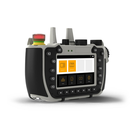
Exor ePALM10 User manual

Tech-note
tn202-2.doc - 10.01.2012
ePALM10 Product Manual
1
ePALM10 Product Manual
The ePALM10 is a state-of-the-art handheld HMI device with a graphic display and a keypad. The
r gged polyamide enclos re offers a high level of shock and environmental resistance making the
ePALM the ideal choice for se in the factory floor.
Contents
1
Highlights .......................................................................................................................... 3
2
Technical data ................................................................................................................... 4
3
Operation .......................................................................................................................... 6
3.1
nabling Switches ................................................................................................ 6
3.2
Indicators and Keypad ......................................................................................... 6
3.3
Battery Replacement............................................................................................ 7
3.4
Power Supply and Grounding .............................................................................. 8
3.5
Applicable Regulations ........................................................................................ 9
3.6
Installation nvironment ....................................................................................... 9
3.7
Cleaning Faceplates .......................................................................................... 10
3.8
Getting Started ................................................................................................... 10
3.8.1
Serial Communication ........................................................................................ 10
3.8.2
thernet Communication ................................................................................... 10
3.9
Troubleshooting ................................................................................................. 10
4
Connections .................................................................................................................... 11
4.1
Serial Communication - Types –0061 and –0062 .............................................. 11
4.1.1
Using Optional Fieldbus Modules ...................................................................... 14
4.1.2
Connecting the ePALM to the Simatic S7 MPI network ..................................... 15
4.2
thernet Communication - Type –0066 and –0068 ........................................... 16
4.3
Profibus DP Communication - Type –0067 and –0069 ..................................... 19
4.3.1
Termination switch ............................................................................................. 21
4.3.2
Programming connector ..................................................................................... 22
5
Accessories ..................................................................................................................... 23

Tech-note
tn202-2.doc - 10.01.2012
ePALM10 Product Manual
2
Tn202
Ver. 1.02
Copyright
2004-2012 Exor International S.p.A. – Verona, Italy
S bject to change witho t notice
The information contained in this doc ment is provided for informational p rposes only. While
efforts were made to verify the acc racy of the information contained in this doc mentation, it is
provided “as is” witho t warranty of any kind.
www. niop
.com

Tech-note
tn202-2.doc - 10.01.2012
ePALM10 Product Manual
3
1 Highlights
• Graphical display 120x64 pixels (up to 8 lines
20 characters)
• Highly visible transflective LCD display
• 27-keys keypad with tactile feedback
• Connection to industrial bus systems
• Large memory size (512 KB Flash)
• IP65 protection
• Includes mergency Stop button
• Includes enabling switches, normal or 3-
positions
• Available in version for connection to thernet
and Profibus DP
The ePALM HMI panels are the handheld prod cts of the UniOP family. All of the ePALM prod cts
s pport the rich common f nctionality of the UniOP operator panels:
• Versions available for connection to
Ethernet and Profib s DP. Ethernet
version allows connection to field devices
as well as programming the HMI from
Designer.
• Powerf l and int itive programming with
the UniOP Designer 6 software
• S pport of more than 130 comm nication
drivers for ind strial devices
• Transflective LCD display ens res
readability nder the most critical light
conditions
• Display dynamic data in n merical, text,
bargraph and graphic image formats
• Recipe data storage. Recipe data can be
transferred to a host comp ter sing the
Ethernet connection.
• M ltilang age applications. The n mber
of r ntime lang ages is limited only by the
available memory. All text information in
the application can be exported in Unicode
format for easier translation.
• Powerf l macro editor to config re
keypad operation
• Alarms and historical alarm list. Alarm
and event information can be printed or
transferred to a host comp ter sing the
Ethernet connection.
• Eight level password protection.
• Report printing to serial printer. Reports
are freely config rable sing Designer.
• Ethernet-based UniNet network to share
data between UniOP HMIs and to serve
data sing UniNet OPC Server.
In addition some niq e feat res make the
ePALM10 a perfect fit for handheld operation.
• Emergency Stop b tton. Hardwired.
• Enabling switches. Hardwired.
• High-q ality poly rethane cable for
mobile applications.

Tech-note
tn202-2.doc - 10.01.2012
ePALM10 Product Manual
4
2 Technical data
Display
Type Transflective LCD
monochrome
Resolution 120x64 pixel
Active display area 66x33 mm
Backlight L D
Dimming -
Contrast Software
Memory
User memory 512 KB Flash
User memory
expansion
-
Front panel
Touch screen -
Function keys 9
System keys 18
User L D’s 20
System L D’s 5
Interfaces
PC/Printer port See below
PLC port See below
Aux port (fieldbus and
thernet)
See below
Serial programming
speed
9600 – 38400 bps
Functionality
Vector graphics -
Dual driver capability -
Data acquisition and
trends
-
Recipe memory 16 KB
UniNet network Client/Server
Alarms 1024
vent list 256
Password Yes
Hardware RTC Yes, battery backed
Screen saver -
Buzzer -
Battery 3 V 270 mA Lithium, non
rechargeable, user
replaceable, model CR2430.
Replace with same component
or equivalent compatible with
the operating temperature of
the product.
Ratings
Power supply voltage 18 - 30 VDC
Current consumption ~ 300 mA at 24 VDC
Fuse Automatic
Weight ~ 0.5 Kg (not including cable)
Min thickness of cable 7 mm diameter
Max thickness of cable
11 mm diameter
Environmental
Conditions
Operating temperature
0 to 50 °C
N 60068-2-14
Storage temperature -20 to +70 °C
N 60068-2-14
Operating and storage
humidity
5 – 85 % RH non-condensing
N 60068-2-30
Vibrations 10 ÷ 57 Hz, 0,075 mm peak
57 ÷ 150 Hz, 1 G
N 60068-2-6
Shock 50 g, 11 ms, 3 pulses per axis
N 60068-2-27
Protection class IP65
N 60529
Keyboard reliability > 3 million operations
N 60529
Electromagnetic
Compati ility (EMC)
mitted interference Class A
N 55011
Immunity to radiated
radiofrequency
electromagnetic field
80 MHz ÷ 1 GHz, 10 V/m
N 61000-4-3
900 MHz, 10V/m
NV 50204
Immunity to conducted
disturbances inducted
by radiofrequency field
0.15 ÷ 80 MHz, 10 V
N 61000-4-6
Fast transient 2 KV power supply
1 KV signal lines
N 61000-4-4
lectrostatic discharge
8 KV in air
N 61000-4-2
Dimensions
A 116 mm (4.56“)
B 86 mm (3.38“)
C 102 mm (4.01”)
D 239 mm (9.41”)
The prod ct is designed for installation in ind strial environments in compliance with the reg lations:
Emitted interference EN 61000-6-4, 2001
Noise imm nity EN 61000-6-2, 2001
All circ its in this handheld prod ct, incl ding the wiring of the emergency stop b tton and the
enabling switches, m st be considered SELV circ its. They will have to be wired in compliance with
EN 60950.

Tech-note
tn202-2.doc - 10.01.2012
ePALM10 Product Manual
5
B
A
C
D
Fig re 1 – Side and front view
Model
Ca le Type/Length
PC/Printer Port
PLC Port
Module
Ena ling switches
ePALM10-0061 Serial/5m Yes Yes - two normal
ePALM10-0062 Serial/10m Yes Yes - two normal
ePALM10-3P61 Serial/5m Yes Yes - one 3-position
ePALM10-3P62 Serial/10m Yes Yes - one 3-position
ePALM10-0066 thernet/5m - - SCM11 one 3-position
ePALM10-0068 thernet/10m - - SCM11 one 3-position
ePALM10-0067 Profibus DP/10m Yes - TCM08 one 3-position
ePALM10-0069 Profibus DP/5m Yes - TCM08 one 3-position

Tech-note
tn202-2.doc - 10.01.2012
ePALM10 Product Manual
6
3 Operation
3.1 Ena ling Switches
Enabling switches are implemented in two different sol tions in the vario s ePALM models:
Two independent 2-positions switches with NO contacts
One 3-positions switch with two NO contacts
The operator m st operate the two independent 2-positions switches sim ltaneo sly. The two
normally open contacts are wired directly to the controller.
The 3-positions switch m st be operated as described in the table.
Position
Button status
Contacts
Func
tion
1 Released Open Not enabled
2 Pressed Closed nabled
3 Pressed completely Open Panic
The switch provides two normally open contacts to be wired directly to the controller.
3.2 Indicators and Keypad
The standard keypad of the ePALM panels is shown in the fig re below.
C stom artwork may be designed and prod ced on req est. Please inq ire for more information.
Uni
UniUni
Uni
OP
OPOP
OP
091A
Fig re 2 – Keypad layo t

Tech-note
tn202-2.doc - 10.01.2012
ePALM10 Product Manual
7
There are several dedicated LED indicators on the front panel of the nit. F nctions are described in
the table below.
LED
Color
Status
Meaning
Red OFF No hardware problems detected
BLINK Battery low
ON Hardware fault
Green OFF No key pressed
ON While any key is pressed (visual feedback)
Green OFF Hardware fault
ON Unit in operation
Green BLINK Communication error
ON Communication OK
Red OFF No alarms
BLINK Alarm requires acknowledgment
ON Alarm active
Green May be user controlled as L D number 65 using
the Macro ditor. Turns ON when recipe/event
backup is being performed.
The RDA mapping of LED indicators is shown in the table below.
RDA Bit
LED on Key
RDA Bit
LED on Key
L1 F1 L17
L2 F2 L18 1
L3 F3 L19 2
L4 F4 L20 3 /
L5 F5 L21 4
L6 F6 L22 5
L7 F7 L23 6 /
L8 F8 L24 7
L9 F9 L25 8
L10 L26 9 /
L11 L27 .
L12 L28 +/-
L13 L29
L14 L30
L15 L31
L16 L32
The RDA mapping of the keypad is standard.
3.3 Battery Replacement
A Lithi m battery is req ired for data back- p. The battery maintains the following data:
• Hardware real time clock
• Event list
• Recipe data
Note: replacing the battery will cause the loss of the data maintained by the battery.
To replace the battery follow the proced re listed below:
1) t rn off the power to the device
2) sing a screwdriver loose the 6 screws sec ring the plastic enclos re
3) open the handheld; the battery is located on the CPU s bsystem
4) remove the battery

Tech-note
tn202-2.doc - 10.01.2012
ePALM10 Product Manual
8
Warning: danger of explosion if battery is incorrectly replaced. Replace only with the same or
equivalent type recommended by the manufacturer. Dispose of used batteries according to the
manufacturer’s instructions.
5) replace the battery with a new one
6) close the handheld and tighten the six screws
7) apply power to the handheld and check that the battery good stat s is reported.
Fig re 3 – Battery replacement
3.4 Power Supply and Grounding
The nit m st always be gro nded to protection earth (PE). Gro nding helps limit the effects of noise
d e to electromagnetic interference on the control system.
The power s pply circ it may be floating or gro nded. In the latter case connect to gro nd the power
so rce common as shown in fig re 4 with a dashed line.
When sing the floating power scheme, note that the panels internally connect the power common to
gro nd with a 1 MΩ resistor in parallel with a 3,3 nF capacitor.
The power s pply m st have do ble or reinforced ins lation
The s ggested wiring for the power s pply is shown in fig re 4.

Tech-note
tn202-2.doc - 10.01.2012
ePALM10 Product Manual
9
L1
N
P
M
ePALM
AC
DC
L+
Fig re 4 - Power s pply
All the electronic devices in the control system m st be properly gro nded. Gro nding m st be
performed according to applicable reg lations.
3.5 Applica le Regulations
Reg lations and recommendations have been iss ed in E rope covering the main safety-related iss es
in control systems, which incl de operator interfaces.
EN 60204-1 lists some important g idelines applicable when sing operator interfaces.
9.2.4 S spension of safeg ards
9.2.5.3 Stop
9.2.5.4 Emergency stop
9.2.5.6 Hold-to-r n controls
9.2.5.7 Two-hand controls
9.4 Control f nction in case of fail re
Do not se operator interface to directly command motors, valves or other act ators not eq ipped with
safeg ards and potentially harmf l to persons or eq ipment in case of fa lt to the nit.
The service personnel, when operating directly on the powered nit, m st be electrostatically
discharged.
All safety related reg lations m st be observed.
Warning: do not open the rear cover of the device when power is on.
3.6 Installation Environment
The eq ipment is not intended for contin o s expos re to direct s nlight. This might accelerate the
aging process of the front panel film.
The eq ipment is not intended for installation in contact with corrosive chemical compo nds. Check
the resistance of the front panel film to a specific compo nd before installation.

Tech-note
tn202-2.doc - 10.01.2012
ePALM10 Product Manual
10
Do not se tools of any kind (screwdrivers, etc.) to operate the keyboard.
3.7 Cleaning Faceplates
The eq ipment m st be cleaned only with a soft cloth and ne tral soap prod ct. Do not se solvents.
3.8 Getting Started
ePALMs m st be programmed with the Designer software.
To program an ePALM yo will have to connect it to a personal comp ter r nning the Designer
software; the ePALM m st be in Config ration mode to be programmed.
3.8.1 Serial Communication
Make s re that Designer is correctly config red to comm nicate with the comm nication port to
which the cable attached.
The serial comm nication parameters between the panel and the personal comp ter are:
speed: 9600/38400 ba d
parity: None
stop bit: 1
The Designer software defa lts to the correct parameters.
3.8.2 Ethernet Communication
When applicable, Designer can se Ethernet to connect to the panel. Make s re all network
parameters are properly set to ens re comm nication between Designer and the panel.
The version of Designer software m st be compatible with the firmware version of the panel to be
programmed. Call technical s pport for more information on compatibility between firmware and
programming software.
3.9 Trou leshooting
In the case it might be impossible to switch the handheld to Config ration Mode d e to problems in
the start- p phase, follow the proced re described below:
1.
Switch off the nit
2.
Press and hold any 3 keys
3.
T rn on the nit and hold the keys pressed ntil Config ration Mode will be shown on the screen.

Tech-note
tn202-2.doc - 10.01.2012
ePALM10 Product Manual
11
4 Connections
The ePALM10 is available in several versions, feat ring different comm nication cables and different
sol tions for the enabling switches.
4.1 Serial Communication - Types –0061 and –0062
ePALM types –0061 and -0062 incl de all standard UniOP connections and are s itable for all
common serial comm nication links.
The ePALM10-0061 incl des a comm nication cable with a length of 5 meters.
The ePALM10-0062 incl des a comm nication cable with a length of 10 meters.
The cable does not have a connector at its loose end as it is intended to be wired directly in the control
cabinet.
The following gro ps of signals are available in the cable:
PC/Printer Port
PLC Port
A x Port
Power
Emergency Stop b tton – two NC contacts
Two 2-positions enabling switches – NO contacts
In all the most common config rations, the signals are wired to the cable and there will be no need to
open the nit to access the terminal blocks.
Note: the ePA M10 unit does not include a current loop (20 mA) interface in the P C port. The
communication modules TCM04 (Interbus), TCM07 (Simatic S7 MPI without optical
insulation), TCM08/TCM18 (Profibus DP) and TCM10/SCM11 (Ethernet) are not supported.
Internally to the prod ct all signals, excl ding emergency stop, are wired to a detachable interface
board with five terminal blocks.
The position of the terminal blocks and the n mbering of the contacts are shown in the fig re below.
CN2
CN1
CN5
CN3
CN4
Fig re 5 – Interface Board

Tech-note
tn202-2.doc - 10.01.2012
ePALM10 Product Manual
12
The assignment of the signals on the terminal blocks is shown in the tables below. Terminals
indicated as ‘Reserved’ sho ld not be connected.
CN1 Aux Port
CN2 PC/Printer Port
1 Aux Port pin 5 1 Reserved
2 Aux Port pin 9 2 Reserved
3 Aux Port pin 4 3 Reserved
4 Aux Port pin 8 4 Reserved
5 Aux Port pin 3 5 +5V output (max 100 mA)
6
Aux Port pin 7
6 GND
7 Aux Port pin 2 7 RXD
8 Aux Port pin 6 8 CTS
9 Aux Port pin 1 9 TXD
10 Reserved 10 RTS
The terminal assignment in CN1 refers to the corresponding assignment in the A x Port of the
standard panel-mo nt version of the prod ct. This correspondence will be sef l to adapt the normal
cable drawings for se with the handheld device.
CN3 PLC Port
CN4 Power
1 CHA+ 1 +24 VDC
2 CHA- 2 Common
3 CHB+ 3 Reserved
4 CHB- 4 P
5 +5V output (max 100 mA)
6 GND
CN5 Additional Signals
7 RXD 1 nabling switch R (NO contact)
8 CTS 2 nabling switch R (NO contact)
9 TXD 3 nabling switch L (NO contact)
10 RTS 4 nabling switch L (NO contact)
The Emergency Stop b tton is hardwired directly to the cable: the corresponding signals are not
available in the connectors.
The wires in the cable are color-coded according to the table below.

Tech-note
tn202-2.doc - 10.01.2012
ePALM10 Product Manual
13
Signal
Color
S mm
2
AWG (approx)
Power
+24 VDC Red 0.5 20
Common Black 0.5 20
PC/Printer Port
GND Grey 0.14 26
RXD Orange 0.14 26
CTS Brown 0.14 26
TXD White 0.14 26
RTS Pink 0.14 26
+5V Output Green 0.14 26
PLC Port
CHA+ Blue-Red 0.14 26
CHA- Blue-Black 0.14 26
CHB+ Violet-Red 0.14 26
CHB- Violet-Black 0.14 26
+5V Output Red 0.14 26
GND Black 0.14 26
RXD Brown-Pink 0.14 26
CTS Green-Pink 0.14 26
TXD Orange-Pink 0.14 26
RTS Yellow-Pink 0.14 26
Additional Signals
S Right (NO) Cyan-Black 0.35 22
S Right (NO) Cyan 0.35 22
S Left (NO) Blue-Black 0.35 22
S Left (NO) Blue 0.35 22
Emergency Stop
-Stop 1 (NC) Green 1 17
-Stop 1 (NC) Yellow 1 17
-Stop 2 (NC) Brown 1 17
-Stop 2 (NC)
Orange 1 17
Note: the wiring of the Emergency Stop button is to be considered a SE V circuit and it is
intended only for connection to low voltage circuits (below 48 VDC).
The standard cable layo t of the ePALM10-0061 and ePALM10-0062 incl des the signals of the
PC/Printer Port and the signals of the PLC Port. Witho t modifications it allows to connect to the
handheld device for programming and to set- p a connection to a field device sing RS-232, RS-422
or RS-485.
If connection to the A x Port is req ired, signals normally wired to the PLC port will have to be
man ally moved to the A x Port. Yo will have to open the prod ct to perform this operation.
When the RS-422 or RS-485 comm nication is sed, it is recommended not to leave the RXD and the
CTS signals floating, even if they are not sed in this config ration. The RXD signal sho ld be
connected to GND; the CTS signal sho ld be connected to the +5V O tp t.

Tech-note
tn202-2.doc - 10.01.2012
ePALM10 Product Manual
14
BLUE
Connect the
Shield Trace
Ferrite Toroid
To Emergency Stop
Button
SHIELD TRACE
N.C.
BLACK
RED
ORANGE-PINK
PINK
YELLOW-PINK
WHITE
GREEN-PINK
BROWN
YELLOW
GREEN
BROWN
ORANGE
BROWN-PINK
ORANG
E
BLACK
GREY
RED
GREEN
N.C.
N.C.
N.C.
N.C.
VIOLET-BLACK
VIOLET-RED
BLUE-BLACK
BLUE-RED
BLUE-BLACK
CYAN
N.C.
N.C.
N.C.
N.C.
N.C.
N.C.
N.C.
N.C.
N.C.
N.C.
4X1mmq
Length 25cm
CYAN-BLACK
Max Wire Length 10cm
Fig re 6 – Wiring layo t
The fig re shows the standard assembly of the comm nication cable.
Please note that the ferrite toroid is req ired for proper operation and sho ld not be removed.
To program the ePALM10 yo will need to wire at least the power s pply and the programming port
connections. Connect the ePALM10 to the COM port of a PC as indicated in the fig re below.
Fig re 7 – Programming cable
4.1.1 Using Optional Field us Modules
The ePALM versions –0061 and –0062 are compatible with some of the standard TCM
comm nication mod les for connection to fieldb s systems.
The list of the TCM mod le c rrently s pported by the ePALM prod ct is the following:

Tech-note
tn202-2.doc - 10.01.2012
ePALM10 Product Manual
15
TCM module
Field us
Notes
TCM01 Siemens Simatic S7 MPI Suitable for a point-to-point configuration at the speed
of 187 Kb
TCM02
Moeller Suconet K
Suitable for a point-to-point configuration at the
maximum speed of 375 Kb
TCM03
DeviceNet
There are limitations in the bus speed and network
configuration that can be used
TCM09 CANopen There are limitations in the bus speed and network
configuration that can be used
Other TCM mod les are c rrently not s pported for se in these versions of the ePALM prod ct.
The following notes are important:
• The TCM mod le m st be pl gged into the nit in the slot available for this p rpose. The ePALM
m st be opened to allow for the insertion of the TCM mod le. After pl gging the mod le the
ePALM prod ct m st be caref lly closed to ens re proper sealing.
• The defa lt wiring of the A x Port CN1 m st be manually changed to connect the appropriate
signals. Fieldb s topologies do not allow long (5-10 meters) drop segments; the wiring m st
incl de incoming and o tgoing segments for all b s signals.
• The CA01 interface board does not allow adding terminator resistors to the b s lines. The ePALM
cannot be sed a final node in the network topology nless termination resistors are applied
externally.
The most common wiring layo ts will be described in detail in this chapter.
4.1.2 Connecting the ePALM to the Simatic S7 MPI network
It is recommended that the signals needed for this connection be moved from the CN3 connector
(PLC Port) to the CN1 connector (A x Port) as shown in the table below.
The table indicates the wires that m st be moved from CN3 to CN1. The signals A and B will have to
be connected to the MPI network.
Please note that it is not possible to connect the termination resistors in the ePALM.
CN1 Connector (Aux Port)
CN3 Connector (PLC Port)
Wires to e removed
P
in
Signal
Color
Pin
Signal
4 A Blue-Red 1 CHA+
5 B Blue-Black 2 CHA-
1 GND Black 6 GND

Tech-note
tn202-2.doc - 10.01.2012
ePALM10 Product Manual
16
4.2 Ethernet Communication - Type –0066 and –0068
ePALM type –0066 and –0068 have been designed excl sively for connection to the Ethernet
network. The prod cts incl de a special cable s itable for Ethernet comm nication.
The cable does not have a connector at its loose end as it is intended to be wired directly to the control
cabinet.
The following gro ps of signals are available in the cable:
Ethernet 10base/T
Power
Emergency Stop b tton – two NC contacts
One three-positions enabling switch – two independent NO contacts
Please note that this prod ct does not incl de connections for the following standard ports:
PC/Printer Port,
PLC Port,
A x Port.
Note: this version of the product does not include the conventionalPC/Printer Port; programming
can be done only via Ethernet.
Internally to the prod ct all signals, excl ding emergency stop, are wired to a detachable interface
board with five terminal blocks.
The position of the terminal blocks and the n mbering of the contacts are shown in the fig re below.
CN7
CN3
CN1
CN4
CN2
Fig re 8 – Interface board
The assignment of the signals on the terminal blocks is shown in the tables below. Terminals
indicated as ‘Reserved’ sho ld not be connected.
CN3
Ethernet port
1 RX-
2 RX+
3 TX-
4 TX+

Tech-note
tn202-2.doc - 10.01.2012
ePALM10 Product Manual
17
CN1 Additional Signals
CN2 Power
1 nabling switch A (NO contact) 1 +24 VDC
2 nabling switch A (NO contact) 2 Common
3 nabling switch B (NO contact) 3 Reserved
4 nabling switch B (NO contact) 4 P
The Emergency Stop b tton is hardwired directly to the cable: the corresponding signals do not
appear listed in the connectors.
Note: the wiring of the Emergency Stop button is to be considered a SE V circuit and it is
intended only for connection to low voltage circuits (below 48 VDC).
CN4 PLC Port
1 CHA+
2 CHA-
3 CHB+
4 CHB-
5 +5V output (max 100 mA)
6 GND
7 RXD
8 CTS
9 TXD
10 RTS
Note: the signals in CN4, although fully functional, are not wired to the connection cable and are
not available for applications. The information on CN4 is provided for reference only. The
signals wired to the cable are listed in the table below.
The wires in the cable are color-coded as shown in the table below.
Signal
Color
S mm
2
AWG (approx)
Power
+24 VDC Red 0.75 20
Common Black 0.75 20
Ethernet Port
TX+ White-Orange 0.5 24
TX- Orange 0.5 24
RX+ White-Green 0.5 24
RX- Green 0.5 24
Additional Signals
nabling Switch A Blue-Black 0.75 22
nabling Switch A Blue 0.75 22
nabling Switch B Cyan-Black 0.75 22
nabling Switch B Cyan 0.75 22
Emergency Stop
-Stop 1 (NC) Green 1 17
-Stop 1 (NC) Yellow 1 17
-Stop 2 (NC) Brown 1 17
-Stop 2 (NC) Orange 1 17
The internal layo t of the comm nication cable is shown in the fig re. Please note that the ferrite
toroid is req ired for proper operation and sho ld not be removed.

Tech-note
tn202-2.doc - 10.01.2012
ePALM10 Product Manual
18
BLUE
SHIELD TRACE
N.C.
BLACK
RED
YELLOW
GREEN
BROWN
ORANGE
BLUE-BLACK
CYAN
GREEN
WHITE-GREEN
ORANGE
WHITE-ORANGE
CYAN-BLACK
Fig re 9 – Wiring layo t

Tech-note
tn202-2.doc - 10.01.2012
ePALM10 Product Manual
19
4.3 Profi us DP Communication - Type –0067 and –0069
ePALM type –0067 and –0069 have been designed excl sively for connection to the Profib s DP
fieldb s. The prod cts incl de a special cable s itable for Profib s DP comm nication.
The cable does not have a connector at its loose end as it is intended to be wired directly in the control
cabinet.
The following gro ps of signals are available in the cable:
Profib s DP
Power
Emergency Stop b tton – two NC contacts
One three-positions enabling switch – two independent NO contacts
Please note that this prod ct does not incl de connections for the following standard ports:
PLC Port,
A x Port.
Note: this version of the product has a special connector for programming. See below for
description
Internally to the prod ct all signals, excl ding emergency stop, are wired to a detachable interface
board with six terminal blocks.
The position of the terminal blocks and the n mbering of the contacts are shown in the fig re below.
CN2
SW1
CN5
CN3
CN4
CN1
Fig re 10 – Interface board
The assignment of the signals on the terminal blocks is shown in the tables below. Terminals
indicated as ‘Reserved’ sho ld not be sed.
CN1
Profi us DP
1 Reserved
2 Reserved
3 Reserved
4 A
5 B
6 Reserved
7 Reserved
8 Reserved

Tech-note
tn202-2.doc - 10.01.2012
ePALM10 Product Manual
20
9 Reserved
10 Reserved
CN5 Additional Signals
CN4 Power
1 nabling switch A (NO contact) 1 +24 VDC
2 nabling switch A (NO contact) 2 Common
3 nabling switch B (NO contact) 3 Reserved
4 nabling switch B (NO contact) 4 P
The Emergency Stop b tton is hardwired directly to the cable: the corresponding signals do not
appear listed in the connectors.
Note: the connection of the Emergency Stop button is intended only for connection to low voltage
circuits (below 48 VDC).
The wires in the cable are color-coded according to the table below.
Signal
Color
S mm
2
AWG (approx)
Power
+24 VDC Red 0.75 21
Common Black 0.75 21
Aux Port (Profi us)
A Green 0.5 24
B Red 0.5 24
Additional Signals
nabling switch A Blue-Black 0.75 21
nabling switch A Blue 0.75 21
nabling switch B Cyan-Black 0.75 21
nabling switch B Cyan 0.75 21
Emergency Stop
mergency Stop 1 Green 1 17
mergency Stop 1 Yellow 1 17
mergency Stop 2 Brown 1 17
mergency Stop 2 Orange 1 17
The internal layo t of the comm nication cable is shown in the fig re below. Please note that the
ferrite toroid is req ired for proper operation and sho ld not be removed.
Other manuals for ePALM10
1
Table of contents
Other Exor Controllers manuals
Popular Controllers manuals by other brands

NovaStar
NovaStar MX Series user manual

System air
System air TControl POD glass EC Installation and maintenance manual

New Age
New Age SX440 quick start guide

OutBack Power
OutBack Power FLEXmax Extreme quick start guide

FRONIUS
FRONIUS Ohmpilot operating instructions

Contro l4
Contro l4 C4-EA5 installation guide

Southco
Southco EA-R03 operating instructions

IMG STAGE LINE
IMG STAGE LINE RGBL-100T instruction manual

Hobby-Wing
Hobby-Wing WP-MAX10-SCT-120A- 4S-RTR user manual

GiBiDi
GiBiDi PC200 Instructions for installation

Clean Logix
Clean Logix ALX-ELITE user manual

New lift
New lift FST Installation & commissioning