bolid RIP-12 User manual

AC line failed, the battery
voltage is below 10.2 V (for
the first two hours) OFF Flashes once
per 1-2 seconds
OFF ON After recovering
mains power test the
battery charge-
discharge cycle *
AC line failed, the battery
voltage is below 10.2 V
(after two hours) OFF Flashes once
every 10 s OFF ON After recovering
mains power test the
battery charge-
discharge cycle *
Note:
•After detaching the battery from the load circuit and recovering utility power it is necessary to check the
battery charge-discharge cycle. If the CHARGE LED has been still lit after 24 hours since having
restored power then the battery operability has to be checked. If extra batteries are connected the charge
time will be increased.
RIP-12 SHUTTING OFF
1. Shut off the mains power supply 220 V.
2. Remove the fuse F1.
3. Detach the battery.
4. Disconnect the load circuit.
MAINTENANCE
The maintenance of RIP-12 is to be carried out annually. The maintaining operations include:
1) RIP-12 visual inspection to discover mechanical injures and to clean any dirt or dust if presented.
2) Measuring the power output parameters and checking them to be in conformance with items of
SPECIFICATION.
3) LED and sound indication testing to meet the requirements of Table above.
4) Proper RIP-12 attaching and contact tightening and wire integrity inspection.
TROUBLESHOOTING
Symptom Reason Human Action
The RIP-12, being powered by
mains power, is not turned on The F1 fuse has blown or wiring
is faulty Measure the voltage across XT1 contacts
before the F1 fuse and after this one,
replace the F1 fuse, repair wiring
The RIP-12, being powered by
the battery, is not turned on The output voltage of the battery
has dropped below 10 V Measure the battery output voltage and
charge or replace the battery, if necessary
MANUFACTURER
ZAO NVP BOLID
#4, Pionerskaya street, Korolev, Moscow Region, Russia, 141070
Tel./fax +7 495 775-71-55
BATTERY BACKED POWER SUPPLY
RIP-12 model 01
INSTRUCTION MANUAL
GENERAL
Battery Backed Power Supply RIP-12 model 01 (referred to as RIP-12 below) is designed to provide electric power
to various fire and intrusion detectors as well as control and indication equipment suited for uninterrupted 12 VDC.
The RIP-12 is round-the-clock operating device with defined output parameters, sealed backup battery being tested
and charged automatically. PIR-12 provides shutting off the battery from load circuit to avoid its unacceptable discharge.
The RIP-12 is equipped with light and audible indication of its current status, i.e. normal or no voltage, battery
charge, output short failure or overload, battery missing or shutting down when discharged.
Being powered by AC power, the RIP-12 provides its outputs against short circuit failures with automatic
recovering output voltage after repairing short circuit failures. Also the RIP-12 protects its outputs against
overvoltage.
Being powered by the backup battery, the RIP-12 provides its outputs against short circuit failures with automatic
recovering output voltage after repairing short circuit failures.
When operated, the RIP-12 should be protected against atmospheric fallout and mechanical damage.
SPECIFICATION
AC Input Voltage Range: from 150 to 250 VAC @ 50 Hz
Backup Power Supply: a battery«Delta» DTM1217 12 V @ 17 Ah or analogous
Output Voltage Range: 13.6 ±0.6 VDC at both AC and charged battery powering;
11.0 VDC min provided the battery is discharged
Load Current Rating: 3.0 А
Maximum Load Current: 4.0 Аfor 10 min, once an hour, at both mains and battery pow.
Input Power: 100 W max at rating voltage
Input Current Consumption: 0.5 A max at rating load
RIP-12 Consumption From the Battery: 40mAmax
Ripple (mVp-p)×2: 120 mV maximum at rating load current
Battery Low Shutdown: 10.2±0.6 VDC
On Battery Run-Time: at least 4 hours for 3 A load current at 25°C
Pre-Operation Time: 6 seconds maximum
Operating Temperature Range: from –10°C to +40°C
Overall Dimensions: 255 mm х310 mm х95 mm
RIP With Battery Weight: 8.5 kg maximum
Software Version 7.1
Typical Lifetime: 10 years, the batterybeing to be replaced onceevery5 year
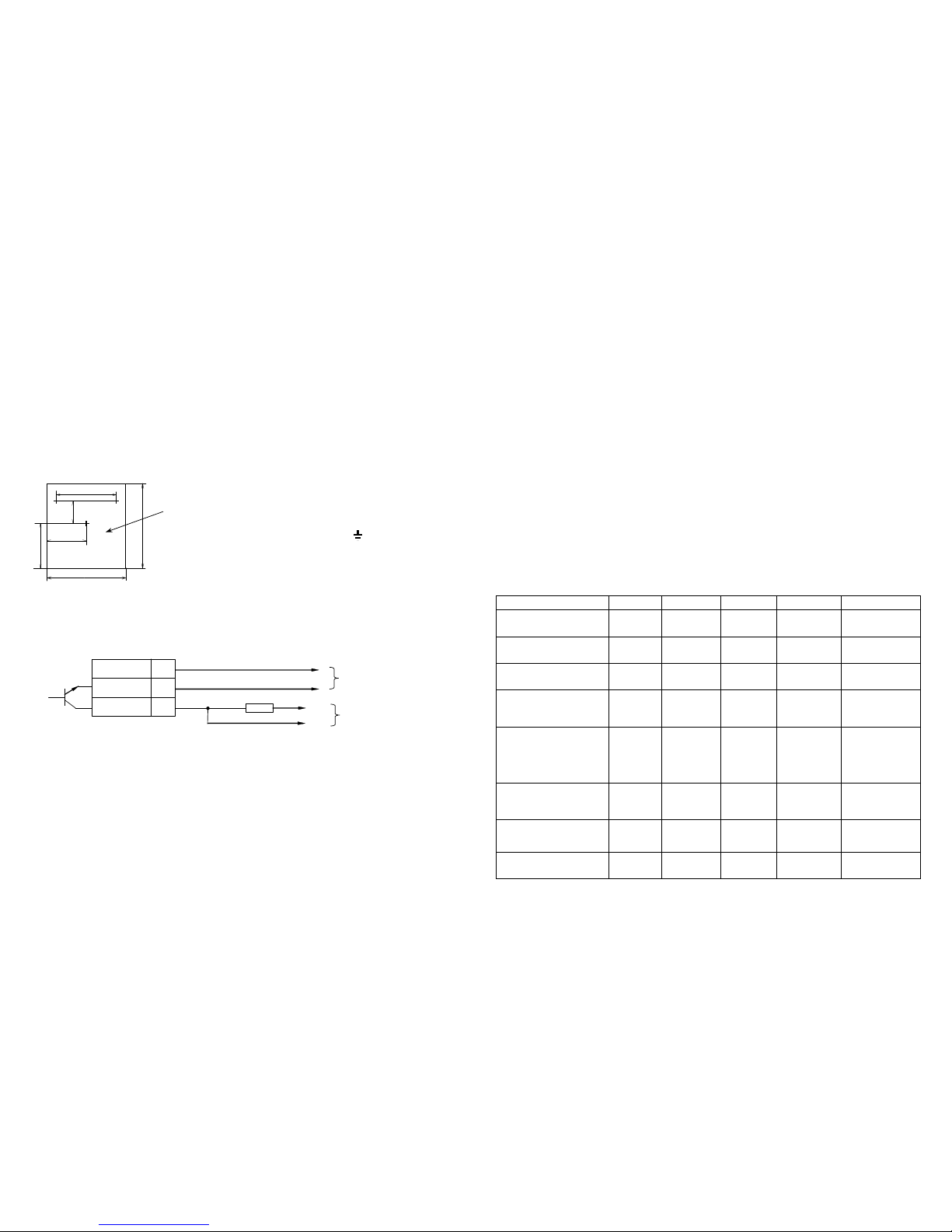
The RIP-12 provides outputting a signal to the NPN output in case of switching to powering by the backup battery
(in state of no mains power) or a short failure in the load circuit. It is opened when AC line fails and the RIP-12 is
operating in battery mode or in case of a short load circuit failure, and it is closed when the RIP-12 is powered by
mains power, so it can be used for remote signaling RIP electric troubles. The maximum NPN output permissible
voltage and commutation current are 30 V and 100 mArespectively.
The RIP-12 is equipped with a tamper switch which terminals are closed in state of the closed RIP-12 door and are
open in state of opening the RIP-12 door. Tamper switch terminals are coupled to the XT2 terminal block.
RIP-12 provides connecting two extra 12 V batteries of 17 Ah each placed in a special Box 2x17Ah toincrease the time
of operation from thebattery (with total capacityof all RIP-12 batteries being of51 Ah).
STANDARD DELIVERY
Battery Backed Power Supply RIP-12 mod.01 1
Instruction Manual 1
Fuse 2А1
Woodscrews 3
Wallplugs 3
Plastic Bushing 2
Lock Key 2

RIP
-
12
mod.01
ХТ
1
0
V Output
2
5
+
OC
Output
1
+
12
V Output
+
–
To the device power
supply leads
R 4.7 k
Ω
ΩΩ
Ω
+loop
–
loop To the device loop
R
is the Loop End-Of-Line Terminator provided along with a device; it is to be installed within RIP-12 enclosure
SAFETY PRECAUTIONS
Current-carrying RIP-12 circuits at 220 V are dangerous and can bring human injure. These circuits are covered by
the protection covering.
Ground the RIP-12 properly before operating.
Do periodically inspect proper RIP-12 grounding and fuse operability.
Never open the RIP-12 unless AC line is shut off.
Never remove the protection covering.
Do shut off AC line power before mounting, installing or maintaining the RIP-12.
Only skilled personnel trained in electric codes and work safety rules should service the device.
ATTENTION!
Connecting the RIP-12 to the mains utility power supply please KEEP UP the correct
coupling of LINE and NEUTRAL TERMINALS in agreement with the picture located inside the cabinet
close to power terminal block.
MOUNTING AND WIRING
8
3
1 2 7
19 0
1
5
0
3 1 0
2 5 5
Note: Load current rating is 3 A. The maximum current consumption from RIP-12 can reach up to 4 A
within 10 minutes. Such a short time increase of current consumption is necessary for sound alarms,
executive devices, and automated fire extinguishing systems powering on. The intervals between heavy
consumption periods must be at least one hour.
4) In order to transmit RIP-12 trouble messages about mains power failed or load circuit shorted remotely, connect
the RIP-12 open collector transistor, or NPN output (+OC output) to an alarm loop of powered control and
indication equipment, e.g. S2000-4, Signal-20, Signal-20P SMD and so on. The example of such wiring is
demonstrated above.
STARTING UP
Before the first turning on ensure the RIP-12 mounting has accomplished correctly.
At first, connect the battery to the terminals taking into account the polarity (the red wire is connected to the
positive lead of the battery). To increase the time of RIP-12 operation from backup power, connect terminals of the
Box 2x17 Ah with two additional batteries installed in parallel across the terminals of the primary backup battery.
Then, insert the fuse F1.
Finally, turn on mains power 220 V@50 Hz.
OPERATING
a) When AC line is on, the LEDs POWER, CHARGE, and 12 V are lit while RIP-12 sounder remains in silence.
Note: The batterybeing completely charged and its voltage being over 13 V, CHARGE LED will not be lit.
b) After RIP-12 powering up the battery is tested. If the battery is not connected or its voltage is below 10 volt then
sounder and CHARGE indicator go off in interrupted mode within 8-10 seconds. After that the sounder silences,
but CHARGE indicator flashed unless the battery is connected. Battery testing procedure is carried out
periodically (at least once every 8 hours). If the battery is found to be missed, then CHARGE indicator flashes.
c) In the events of an output overload (in AC line operating mode) the RIP-12 turns on in the interrupted mode with
the interval of 1–2 seconds until the trouble disappears. In such mode the CHARGE indicator is off but indicators
POWER and 12 V begin to flash once every 1-2 seconds, the sounder being twice turned on with the interval of
1-2 seconds. After disappearing overload the RIP-12 automatically continues normal operating.
d) In the events of short load circuit failure (in AC line operating mode) the RIP-12 turns on in the interrupted mode
with the interval of 1 second until the trouble disappears. The 12 V and CHARGE indicators are off. The
POWER indicator begins to flash once every 1-2 seconds, the sounder being twice turned on with the interval of
1-2 seconds. After output short circuit’s disappearing the RIP-12 automatically continues normal operating.
e) When mains power supply fails the battery is switched to the load circuit, 12 V indicator being turned on and the
sounder going off periodically. The POWER and CHARGE indicators are off, the NPN output being opened
(+OC Output).
f) If the battery voltage has dropped to 11 V the sounder switches on and off five to ten times more rapidly. It is
necessary to take measures to restore mains power line as soon as possible.
g) If the battery voltage has dropped below 10 V, then, to avoid deep discharging the battery, it is shut off from the
load. In such case the POWER and 12 V indicators are off, the CHARGE indicator is flashing, and audible alarm
is sounding within two first hours. In 2 hours the RIP-12 will be transferred to low battery powering mode, with
the CHARGE indicator and sounder turning on once every 10 seconds.
h) If, while RIP-12 operating from the battery, a prohibitive overload or short circuit failure has happened at the
RIP-12 output, the POWER, CHARGE, and 12 V indicators are off, the sounder turning on for a short time every
4-5 seconds. The RIP-12 automatically restores its operability after disconnecting the load circuit and repairing
output overloading.
LEDs and sound indicator behavior along with required human actions are shown in Table below.
RIP-12 Current Status POWER LED
CHARGE LED
12V LED Sounder Human Actions
Mains power is starting up,
the battery is not connected ON Flashes once
every 1-2 s ON
Sounds for 8
-
10
seconds in
interrupted mode
Connect the battery
Normal AC line voltage,
the battery is not charged ON ON ON OFF -
Normal AC line voltage,
the battery is charged ON OFF ON OFF -
Normal AC line voltage, the
battery is charged,
an output overload
Flashes once
every 1-2 s OFF Flashes once
every 1-2 s Beeps twice
every 1-2 s Repair overload
Normal AC line voltage, the
battery is charged,
an output short failure
Flashes once
every 1-2 s OFF OFF Beeps twice
every 1-2 s
Ensure that the
mains power is
on, disconnect all
wires of the load
circuit, and repair
the load short
circuit
AC line failed, an
output short failure or
overload OFF OFF OFF Beeps once per
4-5 seconds
Disconnect all
load circuit wires
and repair the
trouble
AC line failed, the battery
voltage is above 11 V OFF OFF ON Beeps once per
4-5 seconds
Inspect
fuse
F1
operability and
recover the mains
line
AC line failed, the battery
voltage is below 11 V OFF OFF ON Beeps once per
0.5-1 second Repair the AC line
The RIP-12 is to be mounted on a wall or another construction on premises
protected against atmospheric fallout, mechanical damage and unauthorized
access. The RIP-12 mounting dimensions are shown in figure at the left.
Attach the RIP-12 at the selected location.
Then, in accordance with wiring diagram fixed on internal side of RIP-12 door
do the following:
1) Ground the RIP-12 coupling the contact " " located on the input
terminal block with a ground network;
2) Having removed F1 (2 А) fuse, connect mains power supply wires to the
input block terminals;
3)Connect load circuits to the output terminal block XT1 at the PCB keeping the
proper polarity (coupled contacts ХТ1/2,3 to "
+
" and ХТ1/4,5 to "
–
")