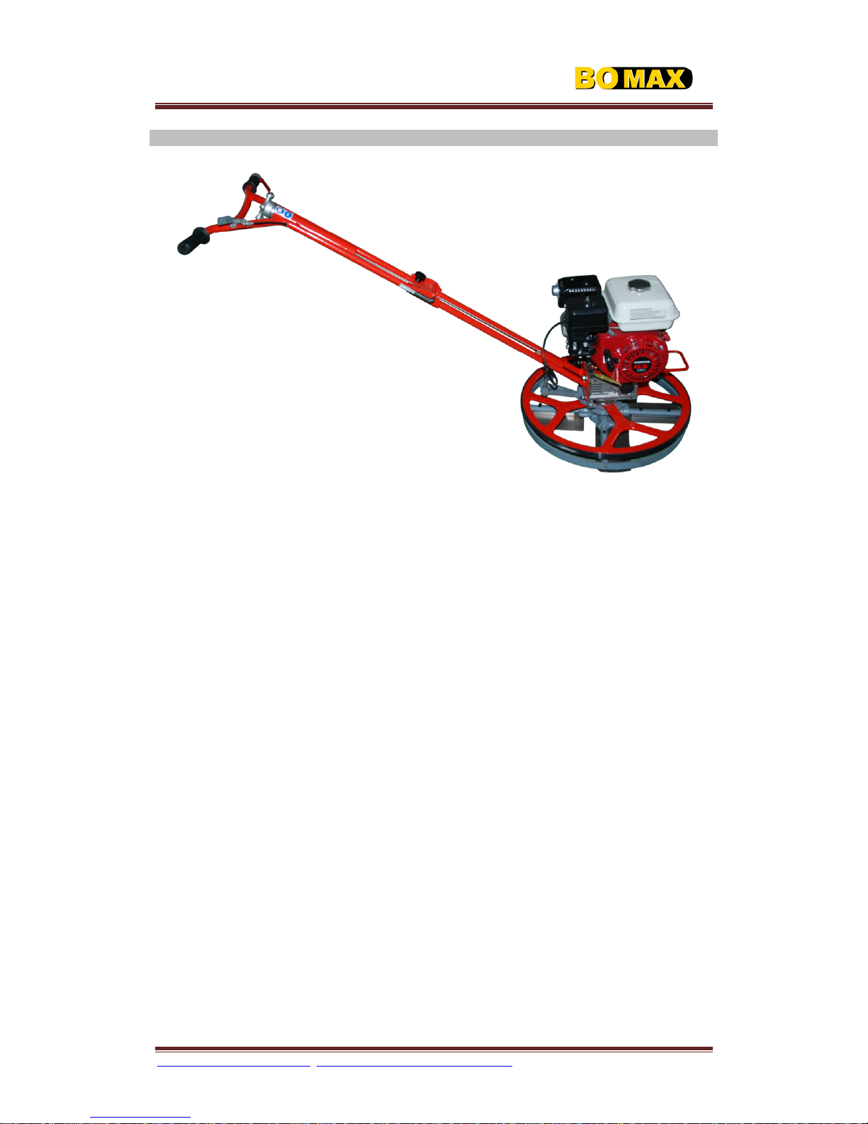
BOMAX BM424 User manual

www.
bomaxengineering
.com
/
webmaster
@
bomaxengineering
.com
/
BM
Owner’s Manual Ver.
0
1
-
2008
Page
1
OPERATION
MANUAL
WALK
-
BEHIND
E
D
G
E
R
TROWEL
PERFORMANCE • EFFICIENT • RELIABLE
Your Model #
: ____________________
Your Serial #
: ____________________

www.
bomaxengineering
.com
/
webmaster
@
bomaxengineering
.com
/
BM
Owner’s Manual Ver.
0
1
-
2008
Page
2
BOMAX
sincerely
thank
s
you for selecting
the
Walk
-
Behind
Edger
Trowel. For you
r safety and
proper operation, before you start to operate or
carry out
any maintenance on this equipment
,
YOU
MUST READ
and
STUDY
this manual
carefully
. Be
sure to always keep it ready for reference.

www.
bomaxengineering
.com
/
webmaster
@
bomaxengineering
.com
/
BM
Owner’s Manual Ver.
0
1
-
2008
Page
3
TABLE OF CONTENTS
Daily Pre
-
Oper
ation Checklist
………………………………….
4
Safety
Alert
& Hazard
Symbols
………………………………….
5
Safety Messages
………………………………………………..
8
Technical Specifications
………………………………………
1
1
Machine Descript
ions
…………………………………………...
1
2
A
s
s
e
m
b
l
y
……………………………………
…
…
…
…
…
…
.
……...
1
3
Pre
-
Operation Inspection
………………………………………
15
Start /
Stop Procedure
……………………………………………
1
6
Operation
………………………………………………………….
1
9
Maintenance
……………………………………………………..
2
1
Stora
ge
………………………………………………………….
2
4
Troubleshooting
…………………………………………………
2
5
Warranty
…………
………………………………………………..
2
6
Notes
……………………………………………………………….
2
7

www.
bomaxengineering
.com
/
webmaster
@
bomaxengineering
.com
/
BM
Owner’s Manual Ver.
0
1
-
2008
Page
4
DAILY PRE
-
OPERATION CHECKLIST
NOTE
Make copies of this checklist and use it on a daily basis.
1.
Engine Oil Level
2.
Gearbox Oil Level
3.
Engine Fuel Level
4
.
Condition
of Blades
5
.
Blade Pitch Operation
6
.
Safety Cut
-
Out Switch Operation
7
.
Fasteners (Bolts & Nuts)
Comments:

www.
bomaxengineering
.com
/
webmaster
@
bomaxengineering
.com
/
BM
Owner’s Manual Ver.
0
1
-
2008
Page
5
SAFETY
ALERT
& HAZARD SYMBOLS
For your safety and the safety of
OTHERS
!
Safety precautions should be followed at all
times when operating this equipment. Failure to read and understand the Safety
Messages and Operation could result in injury to yourself or others.
NOTE
This Owner’s Manual
has been developed to provide complete instructions
for the saf
e
and efficient op
eration of
BOMAX
Walk
-
Behind Power Trowel. Please refer to the engine
manufacturers instructions for related safe operation and maintenance of the engine.
Before using this equipment
, ensure that the operator has read and fully
understands all instruction
s in this manual.
SAFETYALERT SYMBOLS
The following safety alert symbols will inform you about potential hazards that could
injure you or others. They represent the level of exposure to the operator, and are
preceded by one of three words:
DANGER
,
WARN
ING
, or
CAUTION
.
DANGER:
You
WILL
be
KIL
L
ED
or SERIOUSLY injured if you
DO
NOT
follow directions.
WARNING:
You
CAN
be
KILLED
or SERIOUSLY injured if you
DO
NOT
follow directions.
CAUTION:
You
CAN
be injured if you
DO NOT
follow directions.
Pot
ential hazards associated with Pro
-
Series Trowel operation will be referenced with
“Hazard Symbols”
which appear throughout this manual, and will be referenced in
conjunction with
“Safety Alert Symbols”
.
HAZARD SYMBOLS

www.
bomaxengineering
.com
/
webmaster
@
bomaxengineering
.com
/
BM
Owner’s Manual Ver.
0
1
-
2008
Page
6
Lethal Exhaust Fumes
Engine e
xhaust fumes contain poisonous carbon monoxide. This
fume is colorless and odorless, and can cause death if inhaled.
NEVER
operate this equipment in a confined area or enclosed
structure that does not provide ample free flow air.
Explosive Fuel
Gasoline is extremely flammable, and its vapors can cause an
explosion if ignited.
DO NOT
start the engine near spilled fuel or
combustible fluids.
DO NOT
fill the fuel tank while the engine is
running or hot.
DO NOT
overfill tank, since spil
led fuel could ignite if
it comes into contact with hot engine parts or sparks from the ignition
system. Store fuel in approved containers, in well ventilated areas
and away from sparks and flames.
NEVER
use fuel as a cleaning
agent.
Burn Hazards
Engine components can generate extreme heat. To prevent burns,
DO NOT
touch these areas while the engine is running or
immediately after operations.
NEVER
operate the engine with heat
shields or heat guards removed.
Rotating Parts
NEVER
operate equipment with covers, or guards removed. Keep
fingers
,
hands
,
hair
and
clothing
away from all moving parts to
prevent injury.

www.
bomaxengineering
.com
/
webmaster
@
bomaxengineering
.com
/
BM
Owner’s Manual Ver.
0
1
-
2008
Page
7
Accidental Starting
ALWAYS
place the engine ON/OFF switch in the
“O
FF”
position
when the equipment is not in use.
Over Speed Conditions
NEVER
tamper with the factory settings of the engine governor or
settings. Personal injury and damage to the engine or equipment can
result if operating in speed
ranges above maximum allowable.
NOTE
This
equipment
, other property, or the surrounding environment could be damaged if
you do not follow instructions.
Respiratory Hazard
ALWAYS
wear approved respiratory protection.
Sight and
Hearing Hazard
ALWAYS
wear approved eye and hearing protection.
Equipment Damage Messages
Other important messages are provided throughout this manual to help prevent damage
to your equipment, other property, or the surrounding
environment.

www.
bomaxengineering
.com
/
webmaster
@
bomaxengineering
.com
/
BM
Owner’s Manual Ver.
0
1
-
2008
Page
8
SAFETY MESSAGES
CAUTION:
For your own personal safety and those around you,
YOU MUST
READ
and ensure you
FULLY UNDERSTAND
the following safety
information. It is the responsibility of the operator to ensure that
he/she fully understand
s how to operate this equipment safely. In
the event you are unsure about the safe and correct use of the
Power Trowel, please consult your supervisor or nearest
ACE
dealer or
ACE
.
The following safety guidelines should always be use
d when operating the
Walk
-
Behind
Power Trowel.
CAUTION:
IMPROPER
maintenance or use can be hazardous.
READ
and
FULLY UNDERSTAND
this section before you perform any
maintenance, service or repairs.
This equipment
is to be used for its intended application only.
This equip
ment
must be operated only by well
-
trained personnel.
The owner of this equipment
must observe, and train the operator of the equipment
to observe the effective Labor Protection Regulation in the country of application.
Use a suitable lifti
ng equipment t
o lift the equipment
.
Cordon off the work area and keep members of the public and unauthorized
personnel at a safe distance, including animals.
Keep
FINGERS
,
HANDS
,
HAIR
and
CLOTHING
away from moving parts.
Never allow a person to
ac
t as a weight for this equipment
.
Personal Protective Equipment (PPE) must be worn by the operator whenever this
equipment is being used.

www.
bomaxengineering
.com
/
webmaster
@
bomaxengineering
.com
/
BM
Owner’s Manual Ver.
0
1
-
2008
Page
9
Make sure you know h
ow to safely switch this equipment
OFF
before you switch it
ON
in case you get into difficulty.
Always switch
OFF
the engine before
servicing it.
During use, the engine becomes very hot.
Allow the engine to cool before touching
it.
Never leave the engine running and unattended.
Never remove or tamper with
any guards fitted, they are there for your protection.
Always check guards for condition and security. If any are damaged or missing,
DO
NOT USE THE
EQUIPMENT
until the guard has been replaced or repaired.
Do not operate the machine when you are
ill, fee
ling tired, or when under the
influence of alcohol or drugs.
This equipment
is designed to eliminate the possible risks arising from the use of it.
However, risks
DO
reside, and these risks are not clearly foreseeabl
e, and may
cause personal injury or property damage, even possible death. If such unpredictable
and unforeseeable ri
sks become apparent, the equipment
must be stopped
immediately, and operator or his supervisor must take appropriate measures to
eliminate s
uch risks.
It is sometimes necessary to inform the manufacture
r of such
event for
future counter measuring.

www.
bomaxengineering
.com
/
webmaster
@
bomaxengineering
.com
/
BM
Owner’s Manual Ver.
0
1
-
2008
Page
10
WARNING:
Fuel is highly flammable. It may cause injury, death or property
damage.
SHUT DOWN
the engine, extinguish all open flames and
DO NOT
smoke while filling the fuel tank.
ALWAYS
wipe up any
spilled fuel.
Before refueling, switch off the engine and allow it to cool.
When refueling,
DO NOT
smoke or allow
naked flames in the area.
When refueling, use proper funnel, an
d avoid spilling over the engine.
Spilt fuel must be made safe immediately, using sand. If fuel is spilt on your clothes,
change them.
Store fuel in an approved, purpose made container away from heat and ignition
source.
PPE (Personal Protective Equipme
nt)
Suitable PPE must be worn when using this equipment i.e. Safety Goggles, Gloves, Ear
Defenders, Dust Mask and Steel Toe capped footwear (with anti
-
slip soles for added
protection). Wear clothing suitable for the work you are doing. Always protect skin
from
contact with concrete.
FUEL
Do not ingest fuel or inhale fuel vapors and avoid contact with your skin. Wash fuel
splashes immediately. If you get fuel in your eyes, irrigate with copious amounts of water
and seek medical attention as soon as poss
ible.
EXHAUST FUMES

www.
bomaxengineering
.com
/
webmaster
@
bomaxengineering
.com
/
BM
Owner’s Manual Ver.
0
1
-
2008
Page
11
WARNING:
The exhaust fumes produced by the engine are
HIGHLY
toxic and
CAN KILL
!
Do not operate your Power Trowel indoors or in a confined space,
make sure the work area is adequately ventilated.
TECHNICAL SPECIF
ICATIONS
BM4
2
4
MODEL
BM424
DIMENSION (LxWxH)
-
mm (in)
2
0
5
0 x
6
2
0
x 1
010 (8
0
x
2
5
x 40)
GUARD RING DIAMETER
-
mm (in)
610mm (24)
OPERATING WEIGHT
-
kg (lb)
62(113)
HANDLE TYPE
Folder
FINISHING BLADE SIZE (LxW)
-
mm (in)
2
2
8
X
1
2
1
(
9
’
X
4
.
7
5
’
)
NO. OF BLADES
4
BLADE OPERATING SPEED
-
rpm
61
-
131
ENGINE
Honda GX160
ENGINE TYPE
4
-
STROKE GASOLINE
MAX. POWER OUTPUT
-
hp (kW)
5.5 (4.1)
MAX. ENGINE SPEED
-
rpm
3,600
BOMAX
reserves the right to change technical specifications without prior notice and
incurring obligations
.

www.
bomaxengineering
.com
/
webmaster
@
bomaxengineering
.com
/
BM
Owner’s Manual Ver.
0
1
-
2008
Page
12
MACHINE DESCRIPTIONS
BM4
2
4
1.
Electric Cut
-
Out Lever
–
In the event the operator loses control of the Trowel, this
lever will shut down the engine and prevent the handle from spinning.
(
S
t
a
n
d
a
r
d
)
2.
Throttle Lever
–
Controls the speed of
the engine. Pull lever towards the operator to
increase speed (high), push away from the operator to decrease speed (low).
3.
Screw Pitch Control Knob
–
Controls the angle of the blades. Turn clockwise to
increase blade pitch, counter
-
clockwise to decrease b
lade pitch.
4.
Handle
L
o
c
k
B
a
r
–
L
o
c
k
t
h
e
h
a
n
d
l
e
w
h
e
n
e
d
g
e
r
o
p
e
r
a
t
i
n
g
.
5.
U
p
p
e
r
h
a
n
d
l
e
–
6.
L
o
w
h
a
n
d
l
e
–
.
7.
L
o
c
k
n
u
t
–
L
o
o
s
e
t
h
i
s
l
o
c
k
n
u
t
c
a
n
f
o
l
d
t
h
e
u
p
p
e
r
h
a
n
d
l
e
d
o
w
n
w
h
e
n
e
d
g
e
r
t
r
o
w
e
l
s
h
i
p
m
e
n
t
.
8.
Engine
–
Drives the trowel.
9.
Aluminum
W
h
e
e
l
–
function
o
f
r
o
t
a
t
e
w
h
e
n
e
d
g
e
o
p
e
r
a
t
i
n
g
.
10.
Blades
–
This trowel is equipped with
a set of finishing blade as standard. Other
blades can also be fitted depending on type of jobs to be performed. In addition, float
pans can be attached that will allow the trowel to float on wet concrete.
11.
L
i
f
t
i
n
g
h
a
n
d
l
e
–
L
i
f
t
t
h
e
t
o
w
e
l
.
12.
Gearbox
–
R
e
d
u
c
e
t
h
e
e
n
g
i
n
e
s
p
e
e
d
a
n
d
d
r
i
v
i
n
g
s
p
i
d
e
r
.
13.
Stabilizer
Ring
–
Provides safety precaution. Never put hands or feet inside guard
ring when Trowel is running.
1
2
3
4
5
6
7
8
9
10
11
1
2
1
3

www.
bomaxengineering
.com
/
webmaster
@
bomaxengineering
.com
/
BM
Owner’s Manual Ver.
0
1
-
2008
Page
13
NOTE
Due to improve
ments and changes in the equipment, the illustrations shown may be
different from the actual equipment.
ASSEMBLY
1.
Connect the handle assy. to
the four bolts on gear
-
box.
Install the shaft pin inside
the yoke arm.
T
ightened the handle with lock nut.
2.
Engine mounting
Put the engine on mounting base and
install
plate and s
pring washer lock the nut.
3.
Install the drive belt. Adjust the pulley to keep the clutch and
pulley in one line.

www.
bomaxengineering
.com
/
webmaster
@
bomaxengineering
.com
/
BM
Owner’s Manual Ver.
0
1
-
2008
Page
14
4.
Connect one stop wire leader to engine mounting bolt. Another leader to engine
stop connector.
5.
Connect throttle control wi
re to engine.
Set the throttle lever to the idle position by pushing it away from the operator’s
p
osition
towards the engine. Loosen the screw that crimps the throttle cable to allow
free movement
of throttle cable .
Connect the throttle cable to the en
gine. Keep in mind there should be a piece of
wire installed on the machine to show you where to route the throttle cable. When
connecting the cable housing, make sure that no more than 1/4 (6.4mm) of the cable
housing protrudes past the housing clamp on t
he engine.
Tighten the clamp on the throttle control, operator position of the handle.
Honda Engine
5.
Inspect all the screw and lock nut which is safety tightened

www.
bomaxengineering
.com
/
webmaster
@
bomaxengineering
.com
/
BM
Owner’s Manual Ver.
0
1
-
2008
Page
15
PRE
-
OPERATION INSPECTION
CAUTION:
NEVER
operate the Trowel in a confined area
or enclosed structure that does not provide
ample
free flow of air
.
ALWAYS
wear approved eye and hearing protection before
operating the Trowel.
NEVER
place hands or feet inside the guard rings while the engine
is running.
ALWAYS
shut the engine down before performing any
kind o
f maintenance service on the Trowel.
NOTE
The following
Pre
-
Operation Inspection
must be performed before the start of each
work session or after every four hours of use, whichever is first. Please refer to the
maintenance section for detailed guidance.
If any fault is discovered, the Trowel
must
not
be used until the fault is rectified.
1.
Thoroughly inspect the machine for signs of damage. Make sur
e all guards are in
place
and secured.
2.
Check hoses, filler openings, drain plugs and any other areas for s
igns of leakage.
Fix any leaks before operating.
3.
Check the engine oil level and top up as necessary. Use proper engine oil with the
proper viscosit
y
.
(Refer to engine manufacturer manual for specific servicing
instructions
)
Table 1. Engine Oil Type
Seas
on
Temperature
Oil Type
Summer
25°C or Higher
SAE 10W
-
30
Spring / Fall
10°C ~ 25°C
SAE 10W
-
30/20
Winter
0°C or Lower
SAE 10W
-
10
4.
Check the engine fuel level and top up as necessary. Use clean fuel. Use of
contaminated fuel may damage the fuel system.

www.
bomaxengineering
.com
/
webmaster
@
bomaxengineering
.com
/
BM
Owner’s Manual Ver.
0
1
-
2008
Page
16
5.
Check the
engine
air filter is clean. Excessive dirt/dust accumulation within the filter
element will cause erratic engine operation. Clean the air filter element when it
is
contaminated. (See
Maintenance Section)
Explosive Fuel
Fuel
Check
Fuels are highly flammable and can be dangerous if mishandled.
DO NOT
smoke while
refueling.
DO NOT
attempt to refuel the Trowel if the engine is still
hot!
or
running
.
6.
Check for fuel and oil leaks.
7.
Check engine carburetor for external dirt and
dust. Clean with dry compressed air.
8.
Check fastening bolts and nuts for tightness.
9.
Check the gearbox oil is up to point
. If the oil is not up to middle of the oil sight glass,
fill with oil. Below are some compatible gearbox oil
s:
-
Mobil 600W Cylinder
Oil 320
-
BP Energol GRP 320
-
Shell Tevela Oil SC 320 EP
-
AGMA 250.04 Comp.
10.
Check the
V
-
Belt for wear and tear. Replace any worn belts.
11.
Check for worn or damaged blades. Replace any worn blades.
START / STOP PROCEDURE
CAUTION:
IMPROPER
operation can be
hazardous.
READ
and
UNDERSTAND
this section before you start the equipment.
NOTE
Before starting the engine, make sure that the Centrifugal Cut
-
Out Switch is in
ON

www.
bomaxengineering
.com
/
webmaster
@
bomaxengineering
.com
/
BM
Owner’s Manual Ver.
0
1
-
2008
Page
17
position. For Electric Cut
-
Out Lever
(optional)
, make sure the lever is held down to be i
n
the
ON
position. Throttle
Lever is set to low
position.
CAUTION:
NEVER
disable or disconnect the Centrifugal Cut
-
Out Switch or
Electric Cut
-
Out Lever
(optional)
. It is provided for the operators’
safety and injury may result if it is disabled, discon
nected or
improperly maintained.
CAUTION:
The Trowel is
heavy
and
awkward
to move around. Use
appropriate lifting device
and proper heavy lifting procedures.
DO
NOT lift the Trowel by the guard rings.
START PROCEDURE
CAUTION:
DO NOT
attempt to
operate the Trowel until the Safety Information
and Inspection sections of this manual have been
READ
and
thoroughly
UNDERSTOOD
. Depending on engine manufacturer,
operating steps may vary. See engine manufacturers operating
manual.
SHOWN BELOW
HONDAENG
INE
1.
Place the engine
Fuel Valve L
ever
(Figure 1) to the
“ON”
position.
Figure
1
. Engine Fuel Valve Lever
2.
Place the
Choke Lever
(Figure 2) to the
“OPEN”
position.

www.
bomaxengineering
.com
/
webmaster
@
bomaxengineering
.com
/
BM
Owner’s Manual Ver.
0
1
-
2008
Page
18
Figure
2
. Engine Choke Lever
3.
Place t
he Throttle Lever to
“
LOW
”
position
.
CAUTION:
ENSURE
correct starting position. Failure to do so may result in
injuries.
Figure
3. Correct Starting Position
4.
Set the Centrifugal Cut
-
Out Switch to
“ON”
position or
“HOLD”
down the Electric
Cut
-
Out Lev
er
.
5.
Grasp the Recoil Starter Grip (Fig
ure 4
) and pull it out slowly. Pull till resistance is felt,
then continue pulling the Recoil Starter Grip briskly and smoothly to start the engine.
Figure
4
. Recoil Starter Grip

www.
bomaxengineering
.com
/
webmaster
@
bomaxengineering
.com
/
BM
Owner’s Manual Ver.
0
1
-
2008
Page
19
6.
If the engine has started, slowly
return the
Choke Lever
(Figure 2) to the
“CLOSE”
position. If the engine has not started, repeat steps 1 to 5.
7.
Run the engine for several minutes before actual operation.
8.
Place Throttle Lever to
“HIGH”
position to begin troweling operation.
STOP PROCEDU
RE
1.
Return the Throttle Lever to
“LOW”
position.
2.
Switch off the engine.
OPERATION
CAUTION:
Visually check to be sure that the blades are
free
of obstructions
and the area is
clear
for operation.
CAUTION:
NEVER
place hands or fe
et inside the guard rings while operating
this equipment.
CAUTION:
ALWAYS
keep clear of
rotating
or
moving
parts while operating
this equipment.
1.
Get into operator’s position behind the centre of handle
bar
with good footing and
apply the throttle slow
ly until desired speed is obtained. The blades
of the
Trowel
spin in a clockwise direction
(Figure 5
).
All
ACE
Trowels are directed left or right by
applying a slight upward (lifting) or downward (lowering) pressure on the handle
bar

www.
bomaxengineering
.com
/
webmaster
@
bomaxengineering
.com
/
BM
Owner’s Manual Ver.
0
1
-
2008
Page
20
(respectively).
Figu
re 5
. Blade Rotation Direction
Push handle
bar down and Trowel
will move to the right.
Lift handle
bar up and Trowel
will move to the left.
Slightly tw
ist handlebar to the right and the Trowel
will move forward.
Slightly t
wist handlebar to the left and t
he Trowel
will move backward.
Holding the handle
bar
in neutral position, the Trowel
will remain stationary.
PREPARATION OF CONCRETE SURFACE
Use of a mecha
nical or air vibrating screed equipment
to strike the concrete surface to
level will provide good co
mpaction to the slab and produce an ideal surface for finishing.
It should be remembere
d floating/finishing equipment
s will not repair or correct a poorly
screeded slab.
FLOATING OPERATION
Before starting the floating opera
tion, be sure that the Float
Pa
n is cor
rectly mounted on
the
blades. Be
aware that with the blade
arm
s
turning
clockwise, the Float Pan
should be
positioned the same way. The slab will be ready to work for the first floating operation
when the heel of your shoes leave a print of 2~3mm o
n the surface of the slab. On all
other floating operations, the blades should be almost flat. After the floated slab has set
and your footprint is slightly visible, it is ready to start the finishing operation. The timing
of all these operations is depend
ent on weather conditions. After each operation, the
engine should be stopped.
Never park the machine with the engine running, especially during the floating operation
when the concrete is relatively soft. Considering the machine is heavy, should it be le
ft
running on the soft concrete in the same spot, this will cause damage to the finished floor
tolerances.
Table of contents
Other BOMAX Trowel manuals
Popular Trowel manuals by other brands

MULTIQUIP
MULTIQUIP WHITEMAN EPOXY/M Series Operation and parts manual

Beton Trowel
Beton Trowel BT90HF160 instruction manual

MULTIQUIP
MULTIQUIP HHN-31V Operation and parts manual

Master
Master FWT40 Operation manual

Z.I.P.P.ER MASCHINEN
Z.I.P.P.ER MASCHINEN ZI-BG100Y user manual

Toro
Toro 68048 Operator's manual

MULTIQUIP
MULTIQUIP Whiteman series Operation manual

Atlas Copco
Atlas Copco 245 H4 Safety and operating instructions

Flextool
Flextool FP846 operating instructions

Kushlan
Kushlan KPT 36 Operating instructions and parts manual

MQ
MQ BA-SERIES Operation and parts manual

Sima
Sima DUPLO Series Original user guide