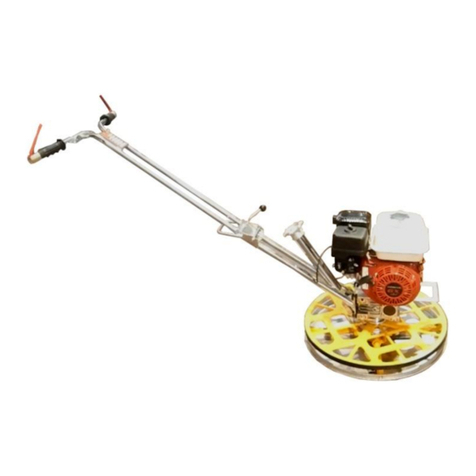
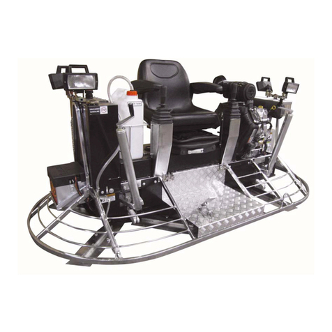
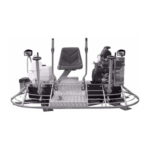
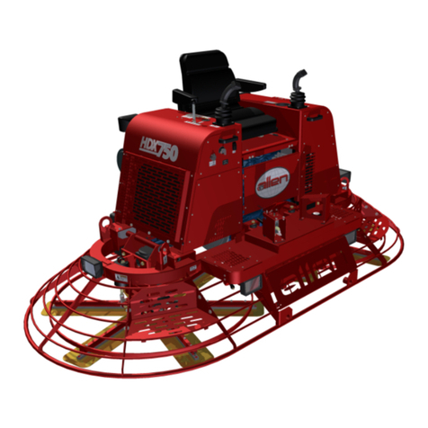
MBW F24 User manual

F24 Electric Trowel Machine
This manual covers the following serial
numbers for each model listed:
F24…….……………1740814-174999
MBW, Inc.
250 Hartford Rd · PO Box
440
Slinger, WI 53086-0440
Phone: (262) 644-5234
Fax: (262) 644-5169
Website: www.mbw.com
MBW (UK) Ltd.
Units 2 & 3 Cochrane Street
Bolton BL3 6BN, England
Phone: 01204 387784
Fax: 01204 387797
L22473 / 05.21.A
© MBW, Inc. 2021
Printed in the USA

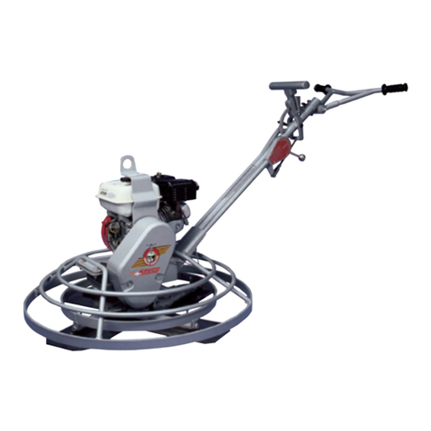
This handbook contains operating and maintenance instructions of the Moskito Edging Trowel,
model CE4-60.
Please keep it in a safe place. You may need to refer to it at a later date.
Follow these instructions carefully in order to become familiar with the trowel and to avoid
problems caused by improper use.
To conform to the safety procedures, it is recommended that the operator wears safety devices such
as safety shoes, soundproof devices, safety helmet and heavy duty leather working gloves.
The manufacturer reserves the right to change the contents of the handbook to improve the quality
of the trowel without notice.
No part of this handbook may be reproduced or translated without written permission from MBW.

Table of contents:
Sections
Description
Page
1.
Introduction........................................................................
4
2.
Technical details.................................................................
4
3.
General instructions...........................................................
4
3.1
Power to the trowel.............................................................
4
3.2
Safety precautions for the operator...................................
5
4.
Starting machine................................................................
6
4.1
Assembly.............................................................................
6
4.2
Before starting....................................................................
6
4.3
Using the trowel..................................................................
7
4.4
Stopping the trowel............................................................
7
5.
General use.........................................................................
7
5.1
Preparation of the concrete surface...................................
7
5.2
Floating operation..............................................................
7
5.3
Finishing operation............................................................
8
5.4
Machine cleaning................................................................
8
5.5
Moving the trowel..............................................................
8
6.
Maintenance.......................................................................
8
6.1
General maintenance..........................................................
9
6.2
Changing floating disc........................................................
9
6.3
Changing blades.................................................................
9
6.4
Changing V-belts................................................................
9
7.
Trouble shooting and repair..............................................
10
8.
Warranty............................................................................
11
9.
Marking and certificate......................................................
12
Attached: declaration of conformity, electrical schedule
and spare parts list

1. I N T R O D U C T I O N
The machine described in this instruction and maintenance manual is a patented mini trowel
provided with a free wheel for floating and finishing concrete, epoxy floors and sub floors.
The trowel is equipped with 4 blades.
The power is transmitted from an electric engine of 220V or 380V through a V-belt to the gearbox.
On request a speed variator can be mounted.
2. T E C H N I C A L D E T A I L S
DESCRIPTION
Unit Measure
Code 3016
Overall dimensions
mm
600x1420x900
Operating weight
Kg
57
Disc diameter
mm
600
Number of blades
nr
4
Horsepower
Kw/HP
3.5HP
Starting
Type
Electric
Voltage
Volt
220V
Frequency
Hertz
50
Cooling
Type
Air
Engine speed
RPM
3600
Blade speed
RPM
130
Packing dimensions
mm
650 x 910 x 800
Shipping weight
Kg
64.52
Tests have been undertaken to determine noise and vibration levels and to evaluate the effect on the
operator. The results are.
Noise and vibration levels in working conditions
Average acoustic pressure
dbA
88.8
Average acoustic power
dbA
103.2
Acoustic pressure on operator
dbA
89.1
Value of vibration
Vibration value on the handle
aw
7.0
It is recommended not to use the trowel for any other purpose than what it is
designed for, unless you have a written authorisation from MBW. In case of
disposal of the machine it is necessary to respect the local environmental law.

3. G E N E R A L I N S T R U C T I O N S
3.1 Power to the trowel
Connection of the trowel must be done as described in the MBW handbook, but MBW is not
responsible for the connection. For safety keep the following points in mind:
1. The power to the trowel is supplied by the electrical network at 220v.
2. The motion of the blades rotation of the trowel is given by the engine to a centrifugal
clutch.
3.2 Safety precautions for the operator
Never start any maintenance or repair while the engine is still running. Be sure the power to the
engine has been turned off and that the connection cables are unplugged.
Before every working day check all power cables for damage such as cuts and peeled wires. Keep
power cables and plugs away from water.
Make sure that nobody stands near the trowel when operating. To avoid unexpected contact with the
rotating parts it is recommended to keep a minimum distance of 4 meters from the operator and the
trowel.
Before every working day check the trowel thoroughly, and pay special attention for loose bolts and
nuts. Be sure that the deadman switches on the trowel are working correctly.
Use the trowel always on a flat level surface.
Do not wear untied clothes, bracelets or other flying objects during the working cycle.
Always wear protective devices such as gloves, safety helmet, safety shoes and others which
conform to the safety regulations.
Always operate the trowel in well lighted areas.
When operation of the machine necessitates walking backwards, ensure that there are no obstacles
in the walking area.
Do not allow minors or untrained people to operate the trowel and keep them away from the
working area.
Store the trowel in a dry place away from rain and other atmospheric influences.
To avoid slipping and loss of control of the trowel, when starting the engine, the
operator must always maintain good footing. Be sure to maintain control at all times,
to avoid possible damage or operator injury. On models equipped with a speed
variator it is recommended to always keep the speed at minimum position during the
starting operation.
Be careful when changing old blades for new. Due to the way the blades wear, the old
blades become sharp like razor blades. Always wear heavy duty working gloves during
the maintenance operation and pay special attention to the position of the blades.
Keep hands and feet away from rotating parts and make sure all safety protection is in
place.
When finishing concrete above ground level or on floors with holes larger than
50x50cm, barriers should be installed as a protective measure. The barrier should be
such that it will stop the trowel from riding over the edge of the slab in case of loss of
control.
Never lift the trowel by the rotating ring; use the handle provided on the trowel.

4. S T A R T I N G T H E T R O W E L
4.1 Assembly
The trowel is delivered in a box completely assembled with the trowel arm folded.
Take the trowel out of the box and place it on a flat level surface to check it.
Contact our dealer in case of damage.
Unfold the handle and fasten the locking knob.
Dispose of the packing in accordance with the standards which are in force in your country.
When moving the trowel from one job site to another use a lifting device, connect hoist hook with
hoisting device.
4.2 Before starting
Before starting the trowel check the following:
The operator must be in good stability condition and must have a good point of support in order to
avoid sudden movements and loss of control of the machine during the starting as well as during the
working process.
Check the deadman levers are working properly and to do this the operator must keep tightly and
firmly the handle of the trowel, on the contrary the operator could loss the control of the machine
causing damages to people or things.
This check must be done on each start.
4.3 Using the trowel
Guiding the trowel on the slab is very simple. Get into operator's position behind the centre of the
handle and attain a good footing and start the trowel.
•Push handle down slightly and the trowel will move to the right.
• Lift handle up slightly and the trowel will move to the left.
• Push forward and the trowel will move forward.
• Pull backward and the trowel will move backward.
• Holding the handle in neutral position the trowel will remain stationary.
4.4 Stopping the trowel
Release the two deadman switches to stop the trowel. After the machine is stopped, disconnect the
trowel to the electric network. The deadmen levers are connected to 2 micro switches that stop the
electricity to the candles.
Be careful when running the trowel on areas where water has been applied because
the trowel will tend to skate away. Maintain full control at all times.
When working on the floor with a trowel, be sure it is done in a safe way. Make sure
there are no obstacles such as manholes or drain ducts on the floor slab, which can
block the rotation of the blades.
Never lift the trowel by the rotating ring.
Never try to change the speed while the engine is stopped. Before stopping the
engine always put the lever at the minimum speed.
It is recommended to hold the handle of the trowel firmly during the work.

5. G E N E R A L U S E
5.1 Preparation of concrete surface
Use a mechanical or air vibrating screeding machine to "strike" the concrete surface to level. This
will provide good compaction to the slab and produce an ideal surface for finishing. It should be
remembered that floating/finishing machines will not repair or correct a poorly screeded slab.
5.2. Floating operation
Before starting the floating operation, be sure the floating disc is correctly mounted underneath the
blades. PAY ATTENTION: THE ROTOR TURNS CLOCKWISE.
The slab will be ready to work for the first floating operation when the heel of the shoes leaves a
print of 2-3mm on the surface of the slab. During the floating operation the floating disc may not
turn on the surface; if so this may be collected cement paste between the blades and the floating
disc. If necessary clean the trowel as indicated in the next sections. After the floated slab has set
and a footprint is slightly visible, it is ready to start the finishing operation. The timing of all these
operations is dependent on weather conditions/ambient air temperature. After each operation the
engine should be stopped. Never park the trowel with the engine running, especially during the
floating operation when the concrete is relatively soft. The trowel should not run on the soft
concrete in same spot, this could cause damage to the finished floor tolerances, producing dips or
hollows.
5.3 Finishing operation
After the floating operation the first thing to do is to remove the floating disc from the blades, and
clean the blades and attaching blade disc of cement paste collected during the floating operation.
Increase the blade pitch up to a maximum of 1 cm for the first finishing operation and then continue
to increase the pitch on the following finishing operations. Continue the finishing passes until you
obtain the desired floor finish. The time required between each finishing pass is again dependent
on the weather conditions and water content of the concrete etc. If some areas of the concrete set /
harden too fast you may apply a small amount of water using a hand brush as an aid to achieving
the finish.
5.4 Machine cleaning
Clean the trowel after it has been used to prevent the collection of hardened cement, which is very
difficult to remove. It can be removed with an old paint brush or hand brush. After cleaning it is
recommended to coat blades, blade arms and protection ring with stripping oil (do not use
flammable oil), this will aid cleaning after the machine is used. Avoid spillage of oil on any rubber
parts like V-belts etc.
5.5. Moving the trowel
When transporting the trowel on a truck, always keep the handle folded and the blades flat in order
not to damage the blade pitch control system.
Always keep the floating disc underneath the blades, to protect them against damage.
Never lift the trowel by the rotating ring; use the hoist hook or handle
provided on the trowel.
Never leave the floating disc attached to the trowel when it is lifting more
than 100cm. The floating disc could fall off.
Be careful when running the trowel on areas where water has been applied
because the trowel will tend to skate away. Be sure to maintain full control
at all times.

6. M A I N T E N A N C E
6.1 General maintenance
The trowel does not need any particular maintenance, however it is necessary to keep following
instructions in mind:
DAILY CHECKS:
•Check daily the condition of the electric components, paying special attention to the electric
cables and plugs.
•Clean the trowel at the end of every working day of cement paste collected while working.
•Check for loose bolts on the blades and tighten if necessary. After daily cleaning is done
attach the floating disc to the trowel to protect the blades during transport.
•Check the deadman lever.
CHECKS AFTER 100 HOURS WORKING:
The oil level in the gearbox; on the box there are two plugs; the one on the top measure the oil level.
Pay attention if you notice oil in the lower part of the trowel; in case, clean and check where it may
come out and make the proper checking. Contact our technical assistance or a qualified technician.
If the grease in the gear box has to be changed or filled up use TEXACO MEROPA 220 or similar
type. Never mix mineral oil with synthetic oil.
ANNUAL CHECKS:
The trowel, after the warranty, must affect annual check on all the safety systems and protection, by
MBW authorised workshops or dealers.
Otherwise MBW will not be responsible.
6.2 Changing floating disc
After the trowel has been cleaned of any cement paste collected during the work, take out the
floating disc from the fastening points.
Before mounting the disc ensure the blades and the floating disc are clean of any cement paste.
Put the floating disc on a flat level surface and be sure the blades are in a horizontal position.
Place the trowel over the disc, so that the finishing blades are pushed in to the two (2) square lugs
on the floating disc.
6.3 Changing blades
Check if the blades are bent or worn.
Follow instructions below to change the blades:
•Clean the blades of hardened cement paste collected during the work.
•Remove bolts and lock washers on each trowel arm.
•Mount new blades and check all bolts and washers; replace if necessary and fasten securely.
•Tighten bolts on blades every day.
•If blades show different wear patterns, replace all the blades for better performance of the trowel.
Before starting any maintenance or repair be sure that the power to the
engine has been turned off and the connection cables unplugged. Make sure
the trowel is clean before starting any maintenance. Always wear heavy
duty working gloves during the maintenance operation and pay special
attention to the position of the blades.
In case of problems contact our technical assistance.

6.4 Changing V-belts
Undertake the following steps to change the V-belts:
•Clean the trowel of any cement paste collected during the work.
•Take the belt guard off by untightening the bolts of each side of the belt guard.
•Replace the V-belts with same size and brand. This is very important, there might be a
difference between one brand and another.
Once the power trowel guarantee has expired, the machines should be subjected to a complete check-up once a
year. You can address to all our authorized dealers all around the world.
MBW will refuse all responsibility in case of incident whenever the check-ups won’t be done.
7. T R O U B L E S H O O T I N G A N D R E P A I R
TROUBLE SHOOTING
CAUSE
REMEDY
The rotor does not turn as fast
as it should
V-belt slack or worn out
Replace V-belt
Trowel does not work properly
1) Blades excessively worn
2) Floating disc not evenly
attached to the blades
1) Replace blades
2) Check if there is any
hardened cement on spider
plate or blades
Trowel leaves swirls on
concrete
1) Hardened cement paste on
blades or disc
2) Blades or disc worn out or
bent
1) Clean blades or disc of
cement paste
2) Change blades or disc
Vibration on the trowel
Loose bolts or nuts on engine
or other parts of the trowel
Check for loose bolts or nuts
and tighten if necessary
Trowel jumps on the floor
1) Trowel arm bent
2) Blades out of adjustment or
bent
1) Replace trowel arm
2) Adjust blades and replace
bent blades
Pitch control does not work
1) Trowel arm bent
2) Hardened cement on spider
plate
3) Handle knob dirty or
jammed
4) Yoke arm broken
1) Replace bent arm
2) Clean spider plate of
hardened cement
3) Clean handle knob
4) Replace yoke arm
Engine won't start
1) Plugs defective
2) No power on line
3) Fuses burnt out
4) Deadman switch broken or
disconnected wire
1) Replace plugs
2) Check all switches
3) Replace fuses
4) Replace deadman switch or
connect wire
Deadman off trowel won't
stop
1) Loose wires
2) Micro-switch burnt out
1) Connect wires
2) Replace micro-switch
Before any maintenance or repair be sure the power to the engine is turned off and
the connection cables unplugged. It is recommended to effect only the operations
described in previous sections. Contact our technical assistance for all other repairs.

8. W A R R A N T Y
New machines sold by the Company are covered by warranty with regard to the structure and the
use of proper materials under following terms:
1) The warranty is valid for twelve (12) months.
2) The manufacturer undertakes to repair or replace at its discretion those parts or assemblies
which it deems to be defective.
3) Parts repaired or replaced are covered by the same warranty as original parts, which expires
twelve (12) months after installation.
4) The manufacturer reserves an adequate period of time to carry out the necessary work and for
the delivery of the spare parts.
5) Transport costs of replacement parts covered by warranty will be charged to the purchaser.
6) This warranty expires if the product is repaired other than by authorised staff during the
warranty period.
7) Replaced parts during the warranty belong to the manufacturer.
8) Any components furnished by the Company but manufactured by others are warranted to the
extent of the original manufacturer's warranty to the Company. Any claims will be handed over
to the buyer.
9) This guarantee is for the sole benefit of the original buyer. Our responsibility under this
guarantee ends in case:
a) The buyer transfers ownership of the trowel;
b) Makes any changes in the trowel;
c) Or adds parts or devices not of our manufacture to the trowel.
10) MBW will not be responsible for damage to floors which might arise from improper
use of the machine, or for any other reason that the machine is stopped during the working
cycle.
11) This warranty does not cover any damages arising from an excessive stress, for instance when
the machine operates after the occurrence of a defect, or from improper use or maintenance,
use of improper materials and failure to comply with the instructions for use.
The same is valid for damage caused by normal wear and tear.
12) The manufacturer shall have no liability for any difficulties arising in re-selling or using broad
due to provisions for the protection of patent rights in force in the country where the machine is
sold.
13) With regard to engines, the terms of warranty of the original manufacturer are valid.
14) The terms of warranty set forth are binding for all MBW Dealers. Any different agreement will
be valid only prior to written confirmation by MBW.
9. M ARKINGANDCERTIFICATE
The models described in this instruction and maintenance manual have been checked to conform to
the machine directives CEE 89/392 including the successive modifications.
The qualification is issued on the CE-label on the machine and on the declaration of conformity
which goes together with this handbook.

Important to buyer: Always keep this guarantee as a reference and give
model number, serial number and/or engine number when writing regarding
your trowel. It will greatly facilitate rapid service.
Other manuals for F24
1
Table of contents
Other MBW Trowel manuals
Popular Trowel manuals by other brands

allen
allen MSP445 Safety & operation manual

Isoplam
Isoplam L030004 Use instructions and maintenance spare parts

MULTIQUIP
MULTIQUIP HPHA36C5H Operation and parts manual

MQ Multiquip
MQ Multiquip WHITEMAN Series Operation manual

MULTIQUIP
MULTIQUIP Whiteman JWN Series Operation and parts manual

MQ Multiquip
MQ Multiquip WHITEMAN B46B90 Operation manual

Zipper Mowers
Zipper Mowers ZI-BG 100 instruction manual

Bartell
Bartell B430 owner's manual

Crown
Crown WBT36 Operator's Safety and Service

HSS Hire
HSS Hire Hire Shops 44216 Operating & safety guide

Contec
Contec CON 60 instruction manual

Marshalltown
Marshalltown Shockwave Power Screed Operations manual and parts book