10 of 68
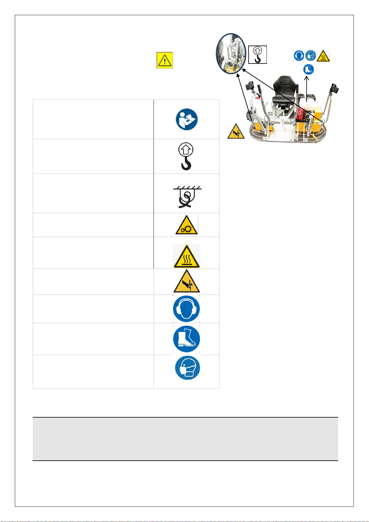
1.3. SYMBOLS AND GLOSSARY
●HAZARD: A potential source
of injury or damage to health;
●HAZARDOUS AREA: Any area within
and/or in the vicinity of the machine
where the presence of a person
constitutes a risk to the health and
safety of the said person;
●EXPOSED PERSON: Any person
wholly or partially located in a
hazardous area;
●OPERATOR: The person or persons
tasked with installing, operating,
adjusting, cleaning, repairing and
moving a machine or performing its
maintenance;
●RISK: Combination of likelihood and
severity of an injury or harm to health
that can arise in a dangerous
situation;
●INTENDED USE: the use of the
machine in accordance with the
information provided in the
Instructions for Use (Par. 2.2);
●ANY REASONABLY
FORESEEABLE MISUSE: Machine
use other than that indicated in the
instructions for use, but that may
derive from the easily predictable
human behaviour;
●HUMAN-MACHINE INTERACTION:
Any situation in which an operator has
to interact with the machine in any of
the operational phases at any
moment in the machine’s life;
●OPERATOR QUALIFICATION:
Minimum level of skills that the
operator must possess in order to
carry out the described operation;
●NUMBER OF OPERATORS:
Appropriate number of operators to
optimally carry out the operation
described and deriving from a careful
analysis conducted by the
"Manufacturer", meanwhile the use of
a different number of
workers could prevent the desi
red
result from being achieved or endanger
the safety of the personnel involved;
●MACHINE STATUS means:
The mode of operation: automatic
gear, manual operation, shutdown.
The condition of the safety devices on
the machine: with or without guards,
emergency shut-down pressed, type
of selection of energy sources, etc.;
●GUARD: Piece of the machine used
specifically for protection through a
material barrier;
●SAFE SHUT-DOWN: Condition of
shut-down obtained with safety
measures which avoid unexpected
start-ups of hazardous parts;
●RESIDUAL RISK: Risk that has not
been possible to eliminate or
sufficiently reduce through the design,
against which the protections are not
(or are not totally) effective;
●The manual gives information of its
existence and instructions/warnings to
avoid it;
●SAFETY COMPONENT: Means a
component used for ensuring a safety
function and whose breakdown or
malfunction affects the safety and/or
health of exposed persons (eg. lifting
device; fixed, mobile, adjustable
guard, etc., electrical, electronic,
optical, pneumatic, hydraulic device,
guard interlocking, etc.).
●ABBREVIATIONS:
●CHAP. = Chapter
●PAR. = Paragraph
●PAG. = Page
●FIG. = Figure
●TAB. = Table
●P.P.E. = Personal protective equipment
●CFR = see