Section 01 MAINTENANCE
Subsection 04 (STORAGE)
01-04-2
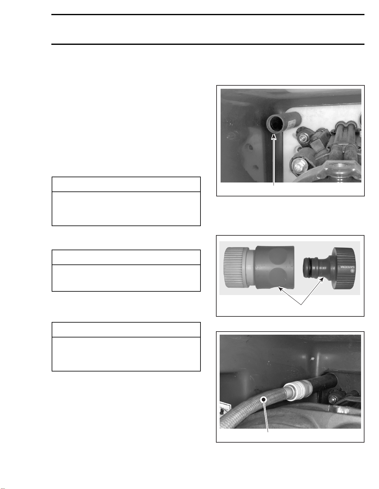
PTO FLYWHEEL
Lubricate PTO flywheel at grease fitting with syn-
thetic grease (P/N 293 550 010).
1. Grease PTO flywheel
Battery
For battery removal, cleaning and storage, refer to
the
1998 Sea-Doo Shop Manual
.
Watercraft Cleaning
Clean the bilge with hot water and mild detergent
or with bilge cleaner. Rinse thoroughly. Lift front
end of watercraft to completely drain bilge. If any
repairs are needed to body or to the hull, touch up
paint and Gelcote®repair kit are available. Replace
damaged labels/decals.
Wash the body with soap and water solution (only
use mild detergent). Rinse thoroughly with fresh
water. Remove marine organisms from the hull.
Apply a nonabrasive wax.
If the watercraft is to be stored outside, cover it
with an opaque tarpaulin to prevent sun rays and
grime from affecting the plastic components, wa-
tercraft finish as well as preventing dust accumu-
lation.
Anticorrosion Treatment
Wipe off any residual water in the engine com-
partment.
Spray BOMBARDIER LUBE lubricant over all me-
tallic components in engine compartment.
Lubricate the throttle cable with BOMBARDIER
LUBE lubricant.
The front seat should be partially left opened dur-
ing storage. This will avoid engine compartment
condensation and possible corrosion.
Additional Recommended Protection
In cool regions (where freezing point may be en-
countered), cooling system should be filled with
water and antifreeze solution.
-CAUTION
Do not lubricate excessively. Immediately
stop when a slight movement is noticed on
rubber boot.
-CAUTION
Never leave any clothing, tool or other ob-
jects near PTO flywheel and drive shaft.
F01I0BA
1
-CAUTION
Never clean fiberglass and plastic parts with
strong detergent, degreasing agent, paint
thinner, acetone, etc.
-CAUTION
The watercraft must never be Ieft in water for
storage. Never leave the watercraft stored in
direct sunlight.
-CAUTION
Always use ethylene-glycol antifreeze con-
taining corrosion inhibitors specifically rec-
ommended for aluminum engines.