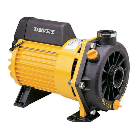
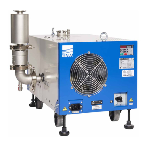
BOMCO F-1300 User manual

BOMCO F-1300/1600 Mud Pump
Instruction Manual
AH13010200SM
AH16010200SM
June, 2007

1
Contents
1. USE OF NEW MUD PUMP........................................................................................................................... 3
1.1 TECHNICAL SPECIFICATION AND PERFORMANCE PARAMETER ............................................................................ 3
1.2. INSTALLATION OF NEW PUMP......................................................................................................................... 5
1.3. REQUIREMENTS FOR SUCTION SYSTEM........................................................................................................... 8
1.4. THE PREPARATION OF POWER END ................................................................................................................ 9
1.5. SPRAY PUMP ASSEMBLY ............................................................................................................................... 10
1.6. THE ASSEMBLY OF FLUID END PARTS............................................................................................................ 12
1.7. DAMPENER ASSEMBLY .................................................................................................................................. 16
1.8 SHEAR SAFETY VALVE.................................................................................................................................... 18
2. LUBRICATION ......................................................................................................................................... 18
2.1 MINIMUM OPERATING SPEEDS ...................................................................................................................... 18
2.2 CONTROLLED FLOW SPLASH SYSTEM ............................................................................................................. 19
2.3 PRESSURE LUBRICATION SYSTEM .................................................................................................................. 20
2.4 MAINTENANCE OF LUBRICATION SYSTEM ....................................................................................................... 22
3. MAINTENANCE........................................................................................................................................ 23
3.1 POWER END ................................................................................................................................................. 23
3.2 ROLLER BEARINGS........................................................................................................................................ 24
3.3 PINION SHAFT ASSEMBLY.............................................................................................................................. 25
3.4 CRANKSHAFT ASSEMBLY ................................................................................................................................26
3.5 INSTALLING CRANKSHAFT ASSEMBLY IN THE FRAME ....................................................................................... 28
3.6 INSTALLING OF CROSSHEAD GUIDES.............................................................................................................. 29
3.7 INSTALLING OF CROSSHEAD .......................................................................................................................... 30
3.8 CHECKING CROSSHEAD ALIGNMENT............................................................................................................... 31
3.9 FLUID END MAINTENANCE ............................................................................................................................ 32
3.9.1 FLUID CYLINDER ....................................................................................................................................... 33
3.9.2 SUCTION MANIFOLD.................................................................................................................................. 34
3.9.3 DISCHARGE MANIFOLD .............................................................................................................................. 34
3.9.4 CYLINDER HEAD FLANGE............................................................................................................................ 35
3.10 WELDING AND REPAIRS .............................................................................................................................. 35
3.10.1 WELDING PROCEDURES........................................................................................................................... 35
3.11 REPAIR VALVE COVER BORE........................................................................................................................ 36
3.12 CHANGE OF DAMPENER BLADDER ................................................................................................................ 36
3.13 APPROXIMATE WEIGHTS OF F-1300/1600 PUMP ASSEMBLIES .................................................................... 37
4. MAINTENANCE OF PUMP..................................................................................................................... 37
4.1 DAILY MAINTENANCE .............................................................................................................................. 37
4.2 WEEKLY MAINTENANCE........................................................................................................................... 38
4.3 MONTHLY MAINTENANCE ........................................................................................................................ 38
4.4 YEARLY MAINTENANCE ............................................................................................................................ 38
4.5 MATTERS NEED ATTENTION IN MAINTENANCE .......................................................................................... 39
5. TROUBLESHOOTING............................................................................................................................. 41
6. MATTERS NEED ATTENTION FOR STORAGE................................................................................. 43
7. EXPLAINS FOR ORDER......................................................................................................................... 43
7.1 PROVIDED RANGE OF MUD PUMP .................................................................................................................... 43
7.2 METRIC SYSTEM AND BRITISH SYSTEM........................................................................................................... 43
7.3 DRIVE ROTATION DIRECTION ......................................................................................................................... 43
8. LUBE APPLICATION GUIDE.......................................................................................... 43
9. F-1300/1600 MUD PUMP PARTS CONTENT................................................................ 44

2
Preface
Thanks for using F series mud pumps produced by Baoji Oilfield Machinery Co., Ltd.
The outline dimension, frame, and fluid end of F-1300 and 1600 mud pump are the same, only the
bearing and gear pair of power end are different. For convenience of customer, this manual introduces
these two kinds mud pumps at the same time.
Instruction manual of F1300/1600 mud pump is a complete document for customers. This manual
offers a plenty of accurate and concise data and operation procedure for reference of operator,
maintenance personnel, and technologists.
It is not intended, nor would it be possible in such limited space, to cover every possible condition
which may be encountered. Strictly operating according to specification and regulation can not only
minimize down-time of mud pump but also prolong service life of equipments.
All specifications and data are in accordance with engineering designs specification and should be
strictly abided during operation, maintenance and repair. For the matching equipments, user should
operate and repair in reference to the documents supplied by original manufacturer.
If this manual has some defects, please present your suggestion and opinion.

3
BOMCO F-1300/1600 is key equipment matched to drilling rig for petroleum well. It is used for
transporting drilling fluid to well bottom by high-pressure manifolds of circulating system in order to
cool off the drill bit, flush the well bottom, crush and take out the rock, and balance the formation
pressure.
The design and manufacture of F series mud pump is in compliance with API Spec. 7K. The module
size of fluid end conforms to API Spec. 7.
1. Use of new mud pump
1.1 Technical Specification and Performance Parameter
1.1.1. Technical Specification
Model F-1300 F-1600
Type Triplex single acting piston pump
Max. Liner size mm 180 180
Rated Power kW 960 1180
Rated stroke spm 120 120
Stroke length mm 305 305
Gear ratio 4.206 4.206
Valve pots API 7#API 7#
Weight kg 24572 24971
1.1.2. Performance data
Performance data of F-1300/1600 Mud Pump data sees table 1A. When imperial system liner is
adopted, the performance data sees table 1B.
1.1.3. Overall Dimension
Overall dimension of F-1300/1600 Mud Pump sees Fig.1.
Table 1A Performance data of F-1300/1600 Mud Pump
Liner Diameter, mm & Rating pressure, MPa(Psi)
180 170 160 150 140 130
F-1300 18.7 2720 21.0 3050 23.7 3440 27.0 3915 31.0 4495 34.5 5000
F-1600 23.1 3345 25.9 3750 29.2 4235 33.2 4820 34.5 5000 34.5 5000
Rating power
F-1300 F-1600
Stroke/minute
kW HP kW HP
Displacement L/S (GPM)
130 1050 1408 1293 1733 50.42
(799)
44.97
(713)
39.83
(631)
35.01
(555)
30.50
(483)
26.30
(417)
*120 969 1300 1193 1600
46.54
(737)
41.51
(658)
36.77
(583)
32.32
(512)
28.15
(446)
24.27
(385)
110 889 1192 1094 1467
42.66
(676)
38.05
(603)
33.71
(534)
29.62
(469)
25.81
(409)
22.25
(352)
100 808 1083 994 1333 38.78
(614)
34.59
(548)
30.64
(485)
26.93
(427)
23.46
(372)
20.23
(320)

4
90 727 975 895 1200
34.90
(553)
31.13
(493)
27.58
(437)
24.24
(384)
21.11
(334)
18.21
(288)
1
0.3878
(6.147)
0.3459
(5.483)
0.3064
(4.857)
0.2693
(4.269)
0.2346
(3.719)
0.2023
(3.206)
Note:
1. Based on 100% volumetric efficiency and 90% mechanical efficiency.
2. *Recommended strokes and input power for continuous service.
Table 1B Performance data of F-1300/1600 Mud Pump
Liner Diameter, in & Rating pressure, MPa(Psi)
7 6 3/4 6 1/2 6 1/4 6 5 1/2 5
F-1300
19.2 278
520.7 299
522.3 323
024.1 349
526.2 379
5 31.1 451
5 34.5
5000
F-1600
23.6 343
025.4 369
027.4 398
029.7 430
532.2 467
0 34.5 500
0 34.5 500
0
Rating power
F-1300 F-1600
Stroke/
minute
kW HP kW HP
Displacement L/S (GPM)
130 1050 1408 1293 1733 49.19
(779)
45.74
(725)
42.41
(672)
39.21
(621)
36.14
(573)
36.36
(481)
25.10
(398)
*120 969 1300 1193 1600 45.40
(719)
42.22
(669)
39.15
(620)
36.20
(573)
33.36
(529)
28.03
(444)
23.16
(367)
110 889 1192 1094 1467
41.62
(659)
38.70
(613)
35.89
(569)
33.18
(526)
30.58
(484)
25.69
(407)
21.23
(336)
100 808 1083 994 1333 37.84
(599)
35.18
(557)
32.62
(517)
30.16
(478)
27.80
(440)
23.36
(370)
19.30
(306)
90 727 975 895 1200 34.05
(540)
31.66
(502)
29.36
(465)
27.15
(430)
25.02
(396)
21.02
(333)
17.37
(275)
1
0.3784
(5.997)
0.3518
(5.577)
0.3262
(5.171)
0.3016
(4.781)
0.2780
(4.406)
0.2336
(3.702)
0.1930
(3.060)
Note:
1. Based on 100% volumetric efficiency and 90% mechanical efficiency.
2. *Recommended strokes and input power for continuous service.

5
Fig.1 Overall dimension of 1300/1600 mud pump
1.2. Installation of New Pump
F-1300/1600 mud pump has been completely assembled and test operated under pressure before
being shipped to the field. Unless otherwise instructed, the lubrication is drained from the power end.
Before putting the pump into service, the precautions and operations must be performed or checked.
In order to prevent personal injury during the performance of any maintenance or inspection
procedures, this equipment MUST BE SHUT DOWN AND NOT OPERATING, and all safety devices on
prime movers and drive devices MUST BE IN THE SAFE POSITION.
The skid under the F-1300/1600 mud pumps is suitable for any type of installation. However, the
support under the pump must be level and adequate to support the self-weight and operating forces
exerted by the pump.

6
Fig. 2
1.2.1. Ground Installation
When ground installation is going on, 8 pieces of 76mm×305mm boards is cushioned in the direction
of pump skid, as indicated in Fig.2. The base of boards should be 300mm wider than that of pump
skid beam. In the wet or moist circumstance, need solider base.
1.2.2. Permanent Installation
When installing mud pump on the structural base or concrete slab of drilling barge and platform, fix
pump skid with bolts, it is essential that the skid should be properly shimmed to prevent possibility of
twisting or distorting the power frame. The pump skids must sit solid on all shim points with bolts
loose.
On barge installations, the pump skids are generally bolted down to T-beams. Install shims at points
shown in Fig, 2 and 3 and observe caution of proper shimming to prevent twist or distortion. The
shims on all installations should extend the full width of the skid beam flanges and have a minimum
length of 12″(305mm).
When prime mover, drive device are installed integrally with the pump skids, the preferred installation
would be to set the pump package on the T-beam skids and provide retention blocks rather than bolts
to hold it in place. This will allow the pump to “float” and minimize the transfer of barge deck or
platform distortion into the frame.

7
Fig. 3
1.2.3. Installations of Driving Device
The drive between the mud pumps and prime mover should be adopted V-belts or multi-row chains
drive, which is installed with precision to assure longest service life and minimum possibility of
unexpected or undesirable shutdowns due to drive failures.
When installing the drive sheave or sprocket, make sure all grease or rust preventative is removed
clearly from the shaft end and the matched bore. Remove all burrs or rough spots from the shaft, key,
and keyway. Fit key to the keyways in both the shaft and drive and install key into shaft keyway.
Coat pinion shaft with light grease of anti-adhesive compound or light oil and install the drive sheave
or sprocket hub. Tighten hub bolts as indicated below:
Use of wrench or lengthening bar to tighten bolt may lead to increase of torque, so it is necessary and
important to tighten bolt according to the following torque values, because in mounting the hub, the
tightening force on the bolts is multiplied many times by the wedging action of the tapered surface.
This action compresses the hub for a snug fit on the shaft. If the bolt-tightening forces are extreme,
bursting pressure is created in the hub of the mounted pulley; this pressure may cause the hub to
crack. The hub bolts should always be tightened alternately, progressively and gradually.
Wrench Torque N.m Wrench Length mm Wrench pull N
810 900 900
Note:N=0.1kgf
1.2.3.1. V-Belt Drives
1. Check sheaves groove condition
Before installing the v-belts, check if sheave grooves is worn or rounded for wearing, worn grooves
will destroy V-belts rapidly. The sidewalls must be straight. In sheave grooves there is no dirt, rust or
other extrusions, which could damage the V-belts.
2. Check alignment of belt pulley
3. Adjust V-belt for previous tension

8
Adjust the belt tension by moving the belt pulley center distance until all of the sag has just been
eliminated from the tight side of the belt and some of the belts on the slack side. Then increase the
given center distance. For example: on 2540mm(100″) Center distance, after adjust center distance
then increase additional 13mm(1/2″). On 3180mm (150″) center distance, after adjust center distance
then increase additional 19.5mm (3/4″).
Do not obtain belt tension by picking up end of pump and allowing belts to tighten under weight of
pump as end is being lowered to the ground.
1.2.3.1 Chain Drive
1) Installation
Proper installation and maintenance of the sprocket and chain drives are essential if good service life
is to be obtained. Since many factors, such as chain width, center distances, speeds, and loads must
be considered when determining the allowable tolerance for sprocket alignment; no good “rule of
thumb” can be applied. The chain alignment must simply be held as nearly perfect as possible. A more
precise alignment can be made by stretching two steel wires (piano wire) along one face of the two
sprockets, one above and the other below the centerline, and moving one of the sprockets until the
wires touch at four points. This will determine that the centerlines of the drives are parallel and the
faces of the sprockets are square.
2) Drive chain lubrication
The pump drive chain lubrication system on the majority of F series of pumps is an independent
system having its own oil pump, reservoir and drive. Fill chain case to the indicated level with lube
grease. Lubricant brand can refer to “Lubrication oil guide of BOMCO products”.
If temperature is below 0ºF, consult department of lube grease supplier for recommendations.
Lube grease should be in accordance to relevant specification and lubrication manual based on
specification.
Chain lubricating system is an independent one, which requires the same maintenance or service
attention employed on any other piece of machinery, includes:
zDaily check of grease level.
zDaily check on condition of lube grease.
zCheck oil pressure. (5-15psi) (0.35-0.103Mpa).
zSupply a volume of grease to chain.
zCheck nozzles in spray tube.
zCheck oil pump drive (V-belts or chain)
NOTE:
1. Oil pressure may be adjusted with the pressure relief adjusting screw on the rear of the pump
housing.
2. Pressure drops may also indicate suction and discharge filter screens need cleaning.
1.3. Requirements for Suction System
For design of suction system of mud pump, individual installation is needed. The suction of the
F-series pumps must have a positive head (pressure) for satisfactory performance. When the optimum
pressures of suction manifold is 0.14~0. 21Mpa (20~30 psi), mud pump has maximum volumetric
efficiency and expendable parts life, which is required with 6 x 8 centrifugal pump (with 45kw,

9
1450-rpm electric motor). The centrifugal pump should be started or stopped automatically and
simultaneously with the drilling pump. On DC electric drilling rig, generally a sign got from DC control
disc excites magnetic starter.
Centrifugal pump also can be driven by belt and the force comes from pinion shaft of pump.
When arranging suction lines, charging pump is adopted by-passed connection, so operation can be
continued even if pump is failed or repaired. Operation without a charging pump, soft suction valve
spring can be used to improve suction performance.
Suction dampener is a very effective aid for improving suction performance and eliminating fluid
pulsations in the suction line, which results in a smoother flow in the discharge line.
Attention: Do not connect the return line of the shear relief valve with suction pipelines
since when relive valve is open, which will cause a sudden risen pressure; when the
pressure is higher than rating pressure value, manifold、suction dampener and centrifugal
pump will be damaged.
1.4. The Preparation of Power End
F-series mud pump has been completely assembled and test operated before being shipped to the
field. Unless otherwise instructed, the lubrication is drained from the power end. Before operating the
pump, the following must be performed or checked.
1.4.1. Power End Lubrication
Before injecting lubricant, open inspection door of cover, check if oil in power end reservoir goes bad,
remove the pipe plugs (No. 2 in Fig.7) on each side of the pump, drain all the remaining lubrication oil
and flush. Add the proper type and quantity of lubrication in the power end (Refer to nameplate on
pump frame for type and quantity required).
Recheck oil level after pump has operated for 15 minutes. Shut pump down and allow approximately
five minutes for the oil level to equalize, Check oil level gauge, (No. 1 in Fig. 7). It is usually necessary
to refill about 10L (3 gallons) oil since a certain amount is retained in the crosshead area and frame
cavities.
1.4.2. Installation of Crosshead Extension Rods and Stuffing Box Seals
Fig. 4

10
⑴stuffing box (2) Bolt (3) Shim (4) O ring (5) spring (6) two-lip oil seal (7) Sealing ring (8) O ring (9)
Locking spring (10) Bolt (11) Bolt (12) O-ring
Refer to Figure 4, remove the stuffing box○
1and mud apron so that crosshead is at the front of the
stroke; thoroughly clean the front of the crosshead and the face of the crosshead extension rod.
Mount position boss of extension rod to the crosshead and tighten the retainer bolts○
2, the torque is
475~500N.m (350~370ft.lbs), at last tighten with iron wire. Thoroughly clean mud apron and the face
of frame, on the “A” place in Fig. 4 mount washer ③and bolt ⑩, tighten it and the torque is
120~160N.m (90~120ft.lbs).
Thoroughly clean the hole and the end face, and meanwhile clean exterior surface of stuffing box and
surface of flange stuffing box plate. Coat the exterior surface of stuffing box with light oil and install
O-ring ○
4. Install stuffing box on the mud guard packing then tighten bolts as the following torque:
16~24N.m (12~18 ft .lbs).
The stuffing box packing assembly consists of two lip oil seal○
6, oil seal ring○
7, O-ring○
12, O-ring○
8
and lock spring○
9. Install the assembly as follows:
Method A:
a) Remove spring○
5from two lip oil seal○
6and mount it on the exterior of the crosshead extension
rod with lip toward power end. Then install spring ○
5on the oil seal lip, and slide them into the
stuffing box. See the following notes.
b) Put the O-ring○12 into Oil Seal ring○7 . Install O-ring○12 and oil seal ring○7 on the extension rod
and then put it into stuffing box bore.
c) Install the O-ring○8 in groove of stuffing box.
d) Installation left/right double lip seal ○
6in the Fig.4 as a).
Note: The double lip seal near power end can be replaced by single lip oil seal, but DO
NOT use the single lip seal in the outer position (fluid end).
e) Install the locking spring○9
a) Take down the stuffing box ○1 from pump frame. Assemble two lip oil seal, oil seal ring○7,
O-ring○12, O-ring○8 andlockspring○9 in the stuffing box as per Fig. 4 of partial enlargement, and
then hook O-ring ○4 over the cylindrical outside surface of the stuffing box ○1.
b) Install the guide sleeve on the front end of Crosshead tension rod as per Fig.4, and coat light
lubricant on the outside surfaces of Crosshead tension rod and the guide sleeve.
c) Mount the stuffing box assembly on Crosshead tension rod through the guide sleeve, pull it into
position by hand, and then fix the stuffing box ○1 on the mud guard packing with spring washer
and bolt (11).
Note: must ensure the pressure spring (5) does not slip out of the groove in the oil seal lip,
as severe scoring of the crosshead extension rod can occur. Coat light lubricant on
extension rod for easy installation of the stuffing box assembly.
1.5. Spray Pump Assembly
Spray pump assembly consists of spray pump, water tank and spray nozzle etc. It functions flushing
and cooling piston and linear during pump operated.
Proper attention must be paid at all times to assure adequate cooling fluid is being applied to the
piston and liner assembly. Stoppage of the cooling fluid will result in almost instant failure of the
piston rubbers and possibly extensive damage to the liner.

11
Stationary spray pipes have been used on F-series pumps Ref. Fig 5. It consists of a fixture frame (1), steel
pipe (2) and spray nozzle (3), it makes cooling fluid spray to piston and liner. Adjust cooling water supply
to the manifold and inspect spray nozzle operation very often to make sure the nozzle is pointed directly at
the piston.
Fig. 5
(1) Fixing frame (2) Steel pipe (3) Spray Nozzle (4) Soft pipe
Cooling fluid is transfused from spray pump (No.3 in Fig .7) through Water tank (No.5. in Fig. 7) to the
manifold on left/right wall plate of the frame. Adjust regulating valve (No.4 in Fig .7) to supply as
much water as possible to the liners without splashing back on the crosshead extension rods. Avoid
some water will work back into the power end to contaminate the lubrication oil.
The cooling fluid returns to the setting chamber from the crosshead extension rod compartment, and
as the fluid overflows through the filter screen between the two sections of the tank, the solids are
allowed to settle out. The filter screen will catch much of the foreign material in the fluid. Refer to
Fig .6.
Check cleanliness of the cooling fluid at frequent intervals and CLEAN and FLUSH reservoir and
replace the cooling fluid as required. Increasing sand grain in contaminated fluid will cause premature
abrasion of liner and piston or stoppage of the spray nozzle or spray tube.
Fig. 6
2
1
43

Fig. 7
⑴Oil level indicator (2) Plug (3) Spray pump (4) Regulating valve (5) Water tank
1.6. The assembly of Fluid End Parts
A profile of the fluid end for F-1300/1600 is shown in Fig, 8. Refer to Fig. 8, clean and assemble the

Instruction Manual for F1300/1600 Mud Pump
13
fluid end parts as following:
Note: Most of the parts in fluid end are designed with metal to metal seating to alleviate
friction wear from breathing action encountered in modern high pressure pump operation.
For this reason it is essential that all parts should be clean and free of rust, nicks and
burrs to ensure reliable seal before being assembled.
Fig. 8 F-1300/1600 Fluid end assembly
1. Wear-resisting plate seal; 2. Wear-resisting plate; 3. Liner flange; 4. Liner seal ring; 5. Liner press
cover; 6. Liner; 7. Liner locking ring; 8. Piston rod; 9. Piston; 10. Piston seal; 11. Nut; 12. Locating
plate; 13. Valve rod guide; 14. Plug plate; 15. Cylinder head seal ring; 16. Cylinder head plug; 17.
Cylinder head; 18. Valve cap seal ring; 19. Mud guard packing; 20. Valve cap
1.6.1. Valves and Seats
Remove three valve caps (20), three cylinder heads (17), and plugs (16) as shown in Fig.8. And
thoroughly clean all machined surfaces in the fluid end with a good cleaning solvent.
Make sure all valve seat bores are very clean and dry (free of dirt, grease, anti-rust compound, etc).
THOROUGHLY CLEAN AND DRY the valve seats and installs suction and discharge valve seats into the
valve pot bores. Drive seats firmly into place with a bar and hammer to ensure contact closely. Install
valves and springs and the other parts.
67
810 911
18 12
13
20
15
14
16
17
12
3
4
5
19

Instruction Manual for F1300/1600 Mud Pump
14
1.6.2. Liners
Installs wear-resisting plate seal (1) in counter bore of fluid end (see Fig. 8). Install wear-resisting
plate (2) through studs until it seats against fluid end. Mount liner flange (3) over studs with the
starting thread at the 5 o’clock position and tighten bolts with 640~690N.m (470~510ft.lbs) torque.
Note: Placing the starting thread at 5 o’clock position to make the liner gland threads
meshing much easier.
Place liner seal (4) in counter bore of wear-resisting plate (2). Apply thin coat of grease to ID of liner
lock (5) and slide over rear of liner (6). Install two-piece liner lock ring (7) in liner groove and O-ring
to hold them in position. Slide liner-handling tool over liner up against liner lock ring and tighten
setscrew to secure it in place. Hoist liner assembly into position with jib hoist. Apply liberal coat of
grease to liner lock threads. Align the starting thread of the liner lock (5) to the 7 o’clock position and
insert the liner into the liner thread ring (3) screw liner lock in until liner seats in position. Tighten with
sledgehammer on hammer lugs.
1.6.3. Piston Rod
Clean piston (9) and piston rod (8), making sure they are free of nicks and burrs. Install piston seal
ring (10) in groove of piston head. Slide piston head (9) on rod while observing that O-ring does not
fall out of groove. Tighten piston rod nut (11) with 1625~2165 N.m (1200~1600ft.lbs.)
Coat grease on liner I.D. and piston O.D. Check ends of piston rod and extension rod to be sure they
are clean and free of burrs. Insert piston rod into liner through cylinder head opening holding piston
rod centered at the rear of the liner. Drive the piston into the liner with a driving tool or a piece of
hardwood and sledgehammer. Use caution as the piston rod approaches the crosshead extension rod
that the dowel on the end of the piston rod is not damaged. The piston rod must be supported and
the dowel guided into the pilot bore.
1.6.4. Piston Rod Clamps
The piston rod clamps are machined as one piece and then sawed in half. The two pieces are with
matching numbers on each half and connected by chain. The two pieces with the same matching
numbers should always be kept together as a set. Install the clamp around the rod end flanges.
Tighten bolt with the following torque values: 330N.m (245ft.ls). before the clamps are installed,
mud guard packing (19) should be installed on the end of crosshead rod.
When piston rods and rod clamp are new, a gap in excess of 5.5mm could be present between the
two halves of the clamp, this is satisfactory provided the faces of the rods are seating metal to metal.
As wear occurs, the halves will pull closer together. Clamping action will be lost when a gap no longer
exists. At this time clamps must be replaced. Install splash plate on rear of liner.
1.6.5. Lower valve Guide and Cylinder Head
Insert the lower valve guide (13), hook it around the stem, insert plug (14) into the locating groove of
valve guide. Mount locating plate (12) in pump head bore, meanwhile install cylinder seal ring (15) on
cylinder plug (16)Start the lock plate (14) and draw it down, compressing the valve spring and seating
Coat seal ring and O.D. of plug with light lubricant. Push cylinder plug into the opening of fluid end.
Grease the cylinder head threads; screw the cylinder head (17) in against the plug (16). Tighten
cylinder head with wrench provided and sledge hammer.
Fluid leakage through the discharge hole indicates a defective seal or loose cylinder head. Should
replace seal or tighten cylinder head in time. DO NOT plug the discharge hole since this can result in
severe damage to cylinder head threads.

Instruction Manual for F1300/1600 Mud Pump
15
1.6.6. Valve Cover
Install valve cover seal ring (18) into bore, and after grease the valve cover seal area and threads
area, tighten the valve covers into place using a sledge hammer and bar.
1.6.7 Discharge Manifold
API 5"(127mm)5000psi flanges are provided on the discharge manifold. Remove discharge flange and
seal gasket area before welding (customer's option for the welding methods) flange on the discharge
piping. Tighten flange connection bolts with 1625-2165 N.m (1200~1600ft.lbs.) torque. Tighten nuts
in a cross-criss order.
1.6.8 Suction Manifold Flange
The suction flange has 3 12" (305mm)connection flanges. Generally they are installed as per oilfield
condition: one is connected with suction manifold inlet, one with suction dampener, and one is
plugged by blankoff flange. An O-ring seals off the connection. Thoroughly clean O-ring groove and
face of flanges before making up connection. Tighten flange bolts with 490~665N.m (360~490ft.lbs).
1.6.9 Auxiliary Manifold
An auxiliary manifold is shown in Fig.9. It can be installed on the discharge manifold opposite the
discharge end. The manifold can connect with KB-75 pulsation dampener (1), shear relief pin (3) and
pressure gauge (2).
Fig. 9
(1) Pulsation dampener (2) pressure gauge (3) shear relief valve (4) Seal washer (5) flange bolt (6)
Discharge four-way joint (7) Seal washer (8)nut (9) Seal washer
An auxiliary manifold connects with discharge manifold by flange. Before assembly thoroughly clean
joint groove of flange, install seal washer (4) and tighten the flange bolts (5) with 1625-2165N.m.
(1200-1600ft.lbs) torque. To assure uniform make-up of seal washer connection, the clearance
between flange end faces should be even, tighten the nuts in a criss-cross order.
The shear relief valve (3) is installed on the auxiliary manifold for the purpose of protecting the pump
from excessively high-pressure overloads. The relief valve must be installed correctly so that is will be
directly contacted with the mud pump. DO NOT PUT ANY TYPE OF SHUT OFF VALAE between the

Instruction Manual for F1300/1600 Mud Pump
16
relief valve and the manifold. Pipe the discharge end of the relief valve directly into the mud pit with
seamless steel pipe as few turns in the line as possible. If the turn must be made, the elbow should
be over120º. IT IS NOT RECOMMENDED for the discharge end of the relief valve to be piped into the
suction line of the pump.
The mounting for KB-75 pulsation dampener (1) is a flange with R-39 seal washer. Before installing
dampener, thoroughly clean ring groove and ring, and after setting dampener into place, tighten the
nut (8) with 950-1265N.m (700-935ft.lbs) torque. Tighten nuts in a criss-cross order.
Both sides of discharge four-way joint are R-27 seal washer flange. Before installing, thoroughly clean
gasket and groove. Connect the bolt and the nut with 495-660N.m (365-490ft.lbs)torque, tighten
nuts in a criss-cross order.
Precharge air or N2 to dampener before starting up pump. See details in “Dampener assembly”
section.
Fig.10 KB-75 Dampener assembly
(1) Gasket ring (2) bottom plug (3) bladder (4) shell assembly (5) cover (6) tee joint (7)
Joint(8)shield of pressure gauge (9) exhaust valve (10) pressure gauge (11) stop valve (12) Washer
(13)Balance disc (14)Press plate (15)Spring washer (R1) stud (R2) nut (R3) stud (R4) nut
1.7. Dampener Assembly
Correct installation and usage of dampener can availably reduce the pressure fluctuation of discharge
system therefore obtaining smoother fluid. For the sake of acquiring long life span of dampener,
usually make pressure of pump and precharge pressure of bladder to keep the suggestion proportion.
It should not be more than 2/3 of the pump discharge pressure, or a maximum of 4.5Mpa. (650psi).
1.7.1 Installation (see Fig.10)
The structure of KB-75 dampener is shown in Fig.10. The pad eyes installed on the pressure gauge

Instruction Manual for F1300/1600 Mud Pump
17
shield ○8 is used for lifting dampener assembly. Before assembly thoroughly clean ring groove, gasket
ring ○1 and groove of mating flange and coat with grease.
Lifting the dampener to the corresponding position of mud pump discharge line, screw nut (R4) with
950~1265N.m (700~935ft.lbs) torque. Assure the connection part is flat and aligned by alternately
tightening the nuts.
1.7.2 Air charging
A set of air charging device is attached when equipment leaves factory(air charging hose assembly of
dampener)please Operate as following procedure: (See Fig. 11)
a) Remove shield of pressure gauge of dampener, rotate valve cover of exhaust about 1/4-1/2 turn
to release the air pressure existed in pressure gauge area, then remove the exhaust valve.
b) Connect hose to the nitrogen cylinder valve and charge valve of dampener.
c) Open the charge valve of dampener.
d) Slowly open the nitrogen cylinder valve, use this valve to adjust incoming N2of dampener.
e) When the pressure gauge of dampener indicates pressure required then shut the nitrogen
cylinder valve.
f) Shut the charge valve of dampener.
g) Remove hose, cover the shield of pressure gauge, and then install the exhaust valve.
For getting best result, Precharge pressure should not be more than 2/3 of the pump discharge
pressure, or a maximum of 4.5 Mpa. (650psi)
Warning:
1. Only charge with compressed nitrogen or air. Do not charge with inflammable and
explosive gas such as oxygen and hydrogen etc.
2. When make maintenance to the dampener, insure both the dampener pressure gangue
and the pump pressure gangue indications is zero. Low pressure can’t be exactly shown
by the dampener pressure gangue, which may cause an accident.
Fig. 11
(1) Nut C5/8″ (2) Seal connector (3) C-type connector hose ⑷Joint (5) Gasket (6)Pipe plug
氮气瓶开关
12 3
空气包充气阀
465

Instruction Manual for F1300/1600 Mud Pump
18
1.8 Shear safety Valve
Fig 12
(1)Connector (2)Retainer Ring (3)Piston Assy. (4)Body (5)Piston Rod (6)Bumper (7)Pin (8)Spring
(9)Safety Cap (10)Shear Bar (11)Shear Pin (12)Warning Plate (13)Pin shaft (14) Retainer Ring
(15)Name Plate (16)Cotter Pin (17)Nut (18)Cap screw (19)Bolt (20)Nut(21)Cap screw
JA-3 shear pin safety valve structure refers to Fig 12. When the pump pressure exceeds the rating
pressure, the force of piston (3) will jack up shear pin plate (10), which will cause the shear pin (11)
broken and the fluid emptying fast.
Change the position of shear pin can adjust the release pressure value. The operation is simple and
reliable.
Each classification work pressure is marked on the shear bar. When adjust the pressure, what to do is
just to put the shear pin in the relevant hole according to the given pressure. Note: There must be
only one shear pin in the shear bar one time! Adjust the pressure with the liner changes.(Refer to
Section 1.1.2)。Wire, arc welding or other alternative material are strictly forbidden, otherwise the
valve pressure is affected which maybe a reverse accident.
2. Lubrication
Proper lubrication of the moving parts in any piece of machinery is the most important since this
directly affects its ultimate life. To obtain maximum trouble-free service life from the power end of
pump, it is necessary to perform routine maintenance care and an inspection to insure the proper
amount of CLEAN lubricant is being provided on the fiction surface of moving parts.
2.1 Minimum Operating Speeds
The F-Series pumps utilize the controlled flow oil bath splash and pressure system to lubricate the
entire power end. The type of pressure system provided in each individual pump will govern the
minimum stroke at which the pump can be operated. The pressure lubricating system of F-1300/1600
mud pump is shown in Fig.13, which can be operated at 25 strokes/minute (oil pressure is 0.035 Mpa;
5psi)

Instruction Manual for F1300/1600 Mud Pump
19
Fig. 13
NOTE: The pressure lubricating oil pump can be mounted on the external of drilling pump
and driven by V-belt; or install the oil pump in the drilling pump driven by the gear ring.
When an internally mounted oil pump is used, the direction of pinion shaft rotation should
be as shown in Fig. 13; when reversing the pump, the inlet/outlet of lubricating pump
must be reversed.
2.2 Controlled Flow Splash System
The controlled flow splash lubrication system is the same on all F-Series pumps, regardless of the type
of oil pump drive provided for the pressure system. In the controlled flow splash system, the main
gear picks oil up from the reservoir, and when the teeth mesh with the pinion, the oil is displaced into
various troughs and compartments in the frame. With reference to Figure 15, the oil thrown into oil
trough (7) is directed through the oil tube (8) to the two pinion bearings.
Oil passage from the top of the crosshead guide compartment to the crosshead bearing is shown in
Figure 14; oil accumulates in the compartment over the crossheads. The oil runs through the nipple (1)
into the crosshead retainer to the oil passages (5) and on to the crosshead pin bearing. As noted, the
duplicate set of oil passages (5) in the crosshead pin permits the crosshead pins to be rotated without
having to give attention to hole alignment. This permits the installation of crosshead pins from either
direction.
油泵齿轮
大齿圈
小齿圈
This manual suits for next models
1
Table of contents
